
Abstract
Well-aligned poly(azo-naphthyl-imide) (PANI) fibers and PANI/multi-walled carbon nanotube (MWCNT) nanofibers-based nanocomposite were produced via self-reinforcement. High-molecular-weight 31 × 103 g mol−1 PANI has been fabricated in this study. Scanning electron microscopy and transmission electron microscopy showed that the electrospun PANI/MWCNT nanofibers were uniformly aligned and almost free of defects. The as-prepared well-aligned electrospun nanofibers were then utilized as homogeneous reinforcement to enhance the tensile strength and toughness of films. Compared with neat 3 wt% PANI nanofibers (304.6 MPa), the tensile strength for the film reinforced with 3 wt% PANI/MWCNT nanofibers (245.9 MPa) was considerably increased. The significant enhancement in the overall tensile properties of the PANI/MWCNT nanofibers-reinforced polyimide films was ascribed to good compatibility between the electrospun nanofibers and the matrix as well as high nanofiber orientation in the matrix. The thermal stability of PANI/MWCNT nanofibers-reinforced polyimide was also superior having 10% gravimetric loss of 599–625°C and glass transition temperature of 243–261 °C relative to the neat polymer and PANI nanofiber-based system. High-performance polyimide nanocomposites via self-reinforcement can act as potential contenders for light-weight aerospace materials.
Introduction
Polyimides have been recognized as one of the significant class of high-performance polymers in several technological applications such as microelectronics, automobile, aviation industry, and so on due to fine chemical, mechanical, and dielectric properties. 1 Polyimides are traditionally synthesized in two steps. The final product is often prepared by chemical or thermal imidization of polyamic acid precursor. Generally, the first step—preparation of polyamic acid—comprises the reaction of an aromatic diamine with an aromatic dianhydride in aprotic polar solvents. 2,3 Bringing materials to the nanometer scale not only improves their properties but also affords its new advanced characteristics beyond bulk materials. Nanofibers, especially polymeric nanofibers, are promising for diverse applications due to large surface to volume ratio, flexibility in surface functionalities, and superior mechanical performance. Among many approaches of fabricating nanofibers, electrospinning, which is also known as electrostatic spinning, is perhaps the most versatile process. Electrostatic spinning has been a useful method to produce nonwoven layers of submicron fibers. Electrospinning has attracted much attention both to academic research and industrial relevance. This technique can fabricate low-cost continuous fibers with diameter down to few nanometers and is applicable to a wide range of synthetic and natural polymers, metals as well as ceramics and composite systems. 4 –6 Electrospinning has thus been viewed as a simple and versatile technique for fabricating ultrafine fibers from materials of diverse origins, for instance, engineering plastics, conductive polymers, block copolymers, polymer blends, ceramics, composite materials, and so on. 7,8 The as-spun fibers are often collected as randomly oriented structure in the form of nonwoven mats due to the bending instability of the highly charged jet. However, other forms of electrospun fibers, such as uniaxially aligned arrays of highly ordered as-spun fibers are used in microelectronics, photonics, and so on. Polymer nanocomposites have attained significant consideration in academia and industry due to enhanced tensile and other physical properties. 9 –12 Owing to high aspect ratio and exceptional properties, fibrous fillers such as carbon nanofibers have been exploited for enhancing the strength and rigidity of polymers. 13 –17 To efficiently develop nanofiber-reinforced polymer nanocomposites, the major concern has been the fine dispersion and orientation of fibers in the matrix. Due to high surface area, homogeneous dispersion of nanofibers in polymer matrices has not been easy to achieve. Poor adhesion at the fiber/matrix interface might result in inadequately dispersed nanomaterial and so degrade the tensile properties. 18,19 Generally, nanofibers have been known not to be well aligned in the matrix impeding the nanofillers from being proficiently used as the ideal reinforcing agent. Incidentally, polyimide has been predominantly attractive for their excellent heat stability and tensile properties and frequently used as high-performance engineering plastics. 20 –22 Polyimide/silica nanotube nanocomposites have been synthesized with improved tensile strength and ductility using aminopropyltriethoxy silane as the coupling agent. It has also been studied that the nitric acid-oxidized carbon fibers improved the tensile characteristics of the polyimide. 23 Nevertheless, most of the nanofiber-reinforced composites require the modification of nanofibers or the use of coupling agents, which may critically affect the properties of the as-prepared nanocomposites. In addition, the nanocomposites with orderly oriented nanofibers have been difficult to fabricate due to their random distribution.
In this research effort, polyimide films were fabricated using well-aligned poly(azo-naphthyl-imide) (PANI) fibers and PANI/multi-walled carbon nanotube (MWCNT) nanofibers as reinforcing fillers via self-reinforcement technique. Fine compatibility between the electrospun nanofibers and the matrix was accomplished simply devoid of chemical modification of the polyimide nanofibers or addition of coupling agent. Afterward, morphological, tensile and thermal properties of nanocomposites have been explored using suitable techniques like scanning electron microscopy (SEM), transmission electron microscopy (TEM), tensile tests, thermogravimetric analysis (TGA), and dynamic mechanical thermal analysis (DMTA). Production of self-reinforced PANI and PANI/MWCNT films was an imperative achievement of this research. Exclusive morphology and enhanced tensile as well as thermal performance render these materials potentially important for light-weight aerospace materials.
Experimental
Materials
MWCNTs were prepared by our patented technology. 24 Pyromellitic dianhydride (PMDA) (97%), 1,5-diaminonaphthalene (97%) 1,4-phenylenediamine (PDA) (97%), and N,N-dimethylacetamide (DMAc) (99%) were procured from Aldrich (St Louis, Missouri, USA). Ammonium thiocyanate (98%) was provided by Fluka (Biocen GmbH, Duesseldorf, Germany). Dimethyl sulfoxide (DMSO) (99%) was obtained from Merck (Nottingham, UK).
Measurements
Infrared (IR) spectra were recorded using Fourier transform IR (FTIR) spectrometer (model: FTSW 300 MX; BIO-RAD, California, USA; 4 cm−1 resolution). Nuclear magnetic resonance (NMR) spectra were scanned at room temperature using Bruker spectrometer (Tokyo, Japan; 300.13 MHz for proton ( 1 H) NMR) in deuterated DMSO. The number and weight-average molecular weight (Mn and Mw, respectively) were calculated through gel permeation chromatography and refractive index detector. Field-emission SEM (FESEM) of freeze-fractured samples was performed using JSM5910 (JEOL, Tokyo, Japan). TEM was performed with a LEO 912 Omega instrument (Carl Zeiss, Germany) at 120 kV. The ultrathin sections were prepared at −60°C with a Leica ultracut E microtome (South Carolina, USA) using diamond knife. Thermal stability was verified using a Mettler Toledo TGA/SDTA 851e (Oakland, California, USA) thermogravimetric analyzer using 1–5 mg of the sample in aluminum oxide crucible at a heating rate of 10°C min−1. DMTA was performed on hybrid materials in the temperature range of 0–300°C with a dynamic mechanical thermal analyzer Q800 (frequency of 5 Hz, heated at 10°C min−1). Stress–strain response of the samples was obtained on a universal testing machine INSTRON 4206 (Norwood, Massachusetts, USA) according to the ASTM 638 method. A crosshead speed of 100 mm min−1 was used during the test.
Synthesis of 1,4-phenylene bis(thiourea)
PDA (0.4 mol), 30 mL of concentrated hydrochloric acid (HCl), ammonium thiocyanate (0.8 mol), and 200 mL of deaerated water were thoroughly mixed and heated in a porcelain dish for 2 h (on a steam bath) and allowed to cool to room temperature. The above mixture was evaporated to dryness for 6–7 h. Afterward, the product obtained was boiled with charcoal (ethanol), filtered, and cooled. 1,4-Phenylene bis(thiourea) was finally recrystallized from ethanol and dried under reduced pressure at 80°C for 24 h. 25
Diazotization
1,5-Diaminonaphthalene (0.04 mol) was added to concentrated HCl (10 mL), and then water 50 mL was also added to dissolve it. The mixture was placed in ice bath to cool to −10°C. Sodium nitrite solution (0.04 mol; 20 mL) was then added with continuous stirring. After the complete addition, mixture was allowed to stir for 1 h at −10°C to avoid the decomposition of diazonium salt. The excess of nitrite was removed by the addition of urea (2 g) with stirring of 0.5 h forming diazonium salt solution.
Synthesis of PANI
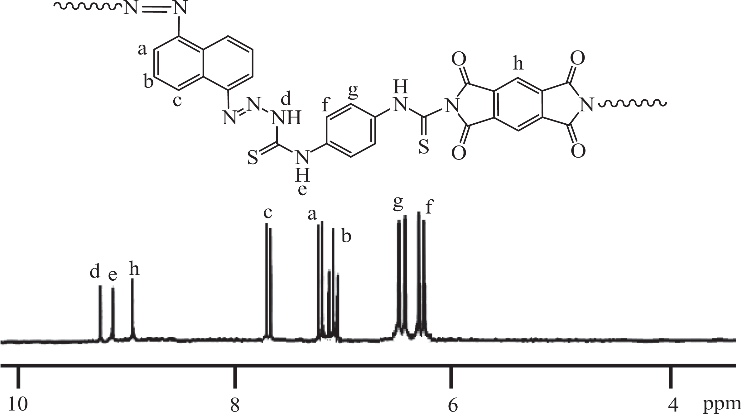
The synthesis of PANI was carried out in a 250-mL round-bottomed flask equipped with a magnetic stirrer, nitrogen gas inlet tube, and calcium chloride drying tube charged with 0.01 mol 1,4-phenylene bis(thiourea), and 50 mL DMAc. The mixture was stirred at 0°C for 0.5 h. Then, 0.01 mol PMDA and diazonium salt solution were added, and the mixture was again stirred at 0°C for 1 h. Later, the mixture was stirred at room temperature for 24 h. The poly(amic acid) was precipitated by pouring the flask content into 200 mL water and methanol mixture. Then, it was filtered, washed with hot water, and dried overnight under vacuum dried at 70°C. A 250-mL two-necked round-bottomed flask equipped with a magnetic stirrer, nitrogen gas inlet tube was charged with 1.0 g of poly(amic acid) and 5 mL of dry DMAc and stirred. The mixture was stirred and afterward 5 mL acetic anhydride and 2.5 mL of pyridine were added. The above mixture was again stirred for 0.5 h and then heated to 80°C and held for 6 h at the same temperature. Then, the mixture was cooled and poured into water. Finally, it was filtered, washed with hot water and methanol, and also dried under vacuum at 90°C (Figure 1). PANI was found to have fairly high-molecular–weight, that is, Mn: 12 × 103 and Mw: 31 × 103 g mol−1. Spectral data substantiated the structure of the synthesized polymers FTIR and 1 H NMR analysis of the polymer is given in Table 1. Figure 2 represents the 1 H NMR analysis of PANI.
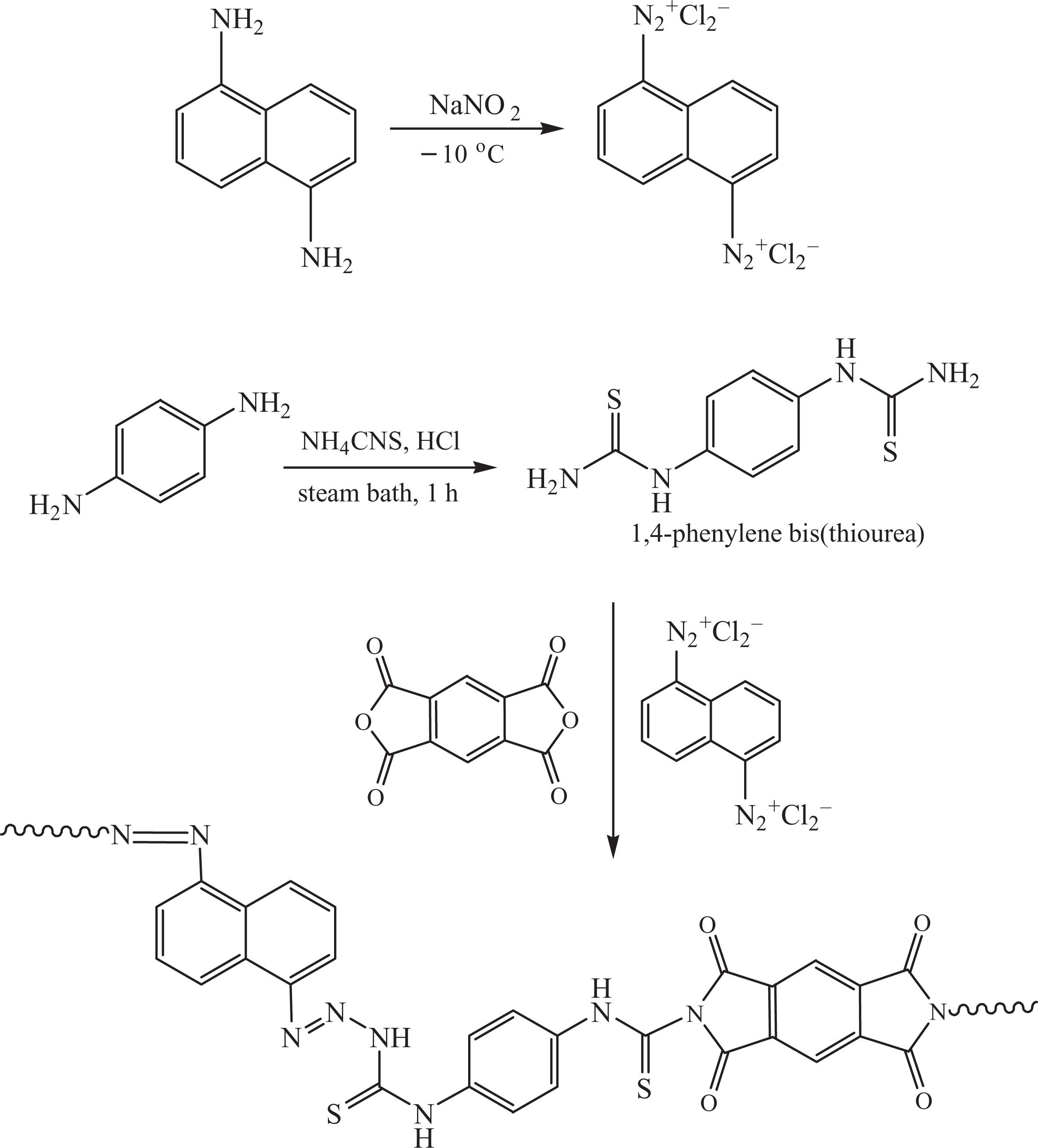
Preparation of poly(azo-naphthyl-imide).
Structural analysis data of neat polymer, PANI, and PANI/MWCNT nanofiber film.
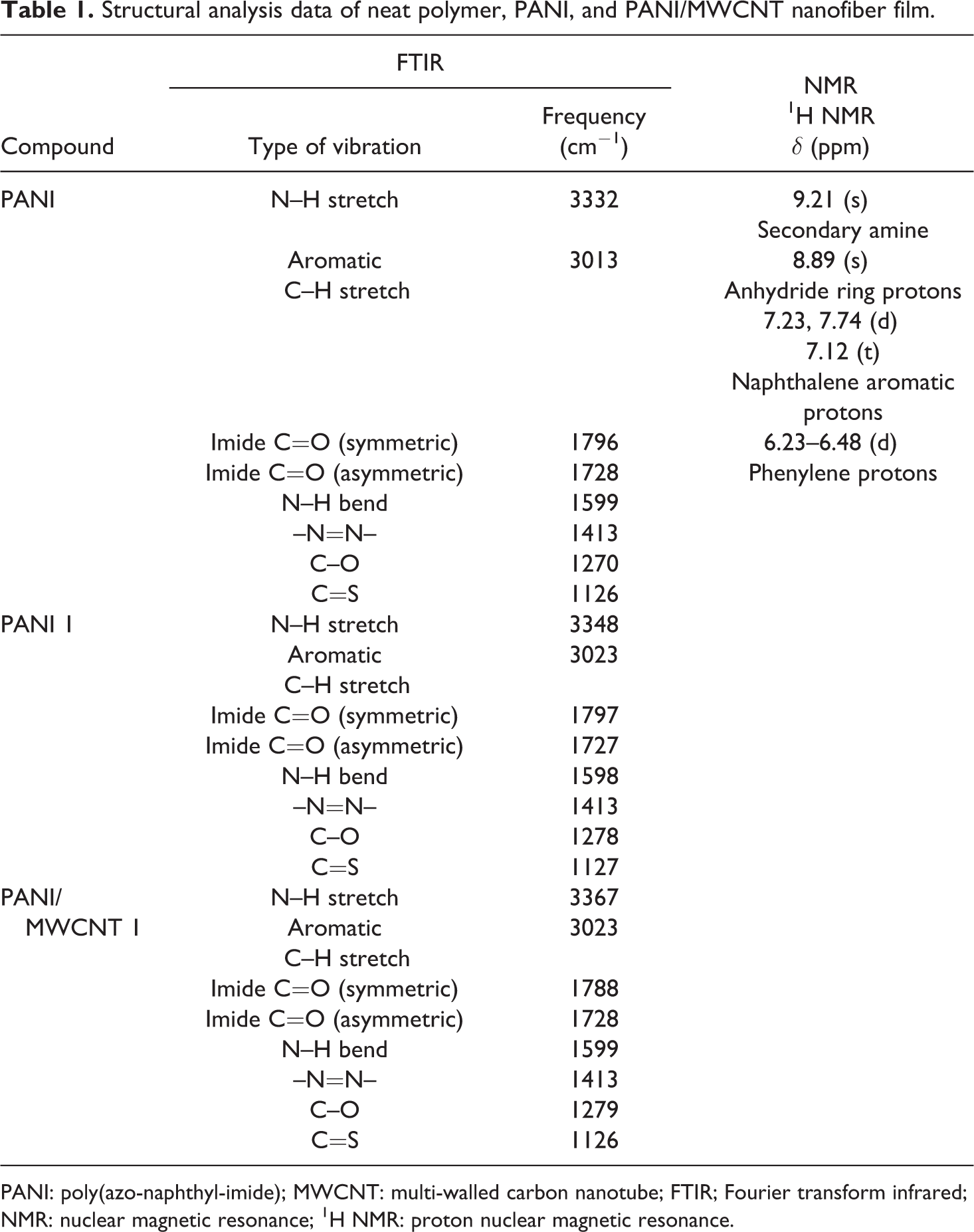
PANI: poly(azo-naphthyl-imide); MWCNT: multi-walled carbon nanotube; FTIR; Fourier transform infrared; NMR: nuclear magnetic resonance; 1 H NMR: proton nuclear magnetic resonance.
Solution preparation
The precursor of polyimide, poly(amic acid) of PANI (PANI-PAA), was synthesized as described above. The polycondensation was performed in DMAc at 0°C, and the solid content of the pristine PANI-PAA solution was 25 wt%. For the preparation of neat PANI-PAA solution used for electrospinning, it was diluted with DMAc; and for MWCNT (5 wt%)/PANI-PAA solution, the pristine PANI-PAA solution was diluted by MWCNT(5 wt%) in DMAc solution. Prior to solution mixing, the MWCNT/DMAc solution was sonicated for 2 h to disperse the CNT homogeneously. Acetic anhydride and pyridine (2:1) was also added to the solutions.
Imidization of nanofibers via electrospinning
Electrospinning was carried out using a syringe with a spinneret (diameter 0.5 mm) and 25 kV applied voltage at 30°C. The feeding rate was 0.25 mL h−1 and the spinneret–collector distance was set to be 10 cm. Neat poly(azo-naphthyl-imide) and PANI/MWCNT-based nanofibers were collected using a rotating disk collector (diameter 0.30 m; width 10 mm). During electrospinning, the linear speed of rotating collector was about 10 ms−1. All the electrospun nanofibers were dried at 80°C for 4 h to remove the residual solvent.
Preparation of nanofibers-reinforced films
The desired amount of as-prepared electrospun (neat PANI and PANI/MWCNT) nanofibers were immersed in the solution of PANI (1 g in 10 mL DMAc) for 1 h and heated to 80°C to obtain the nanofiber-reinforced nanocomposite films. Table 1 shows the structural characterization of PANI/MWCNT nanofiber-reinforced nanocomposite.
Results and discussion
Tensile properties
Figure 3 reveals the stress–strain curves of neat cast PANI film and nanofiber-reinforced films. The tensile properties such as tensile strength, tensile modulus, and elongation at break are listed in Table 2. The number in the sample designation signifies weight percentage (wt%) of nanofibers in the sample. Tensile strength of electrospun PANI/MWCNT nanofiber-reinforced films was much higher than those containing PANI nanofiber, due to fine alignment of the PANI/MWCNT electrospun nanofibers in the film. Electrospinning has been known as a facile method for obtaining high orientation of polymer chains in the nanofibers. The considerable improvement in tensile properties of neat PANI/MWCNT nanofiber-reinforced PANI films was attributed to (i) possible interaction in PANI/MWCNT fibers (Figure (4)); (ii) high orientation of nanotubes in the electrospun PANI/MWCNT nanofibers; and (iii) high orientation of electrospun PANI/MWCNT nanofibers in the films. The PANI nanofiber-reinforced films were nearly transparent because of the good compatibility between the nanofibers and matrix. The noteworthy enhancement in tensile properties of PANI films were credited to the fine compatibility and strong interfacial interaction between nanofibers and matrix. The optimal tensile properties were achieved for the PANI film reinforced with 3 wt% PANI/MWCNT nanofibers. Compared with tensile stress of 1 wt% PANI/MWCNT nanofiber-reinforced film 270.6 MPa, the film reinforced with 3 wt% PANI/MWCNT nanofibers showed higher value 304.6 MPa. Additionally, for the PANI/MWCNT nanofibers-reinforced PANI films, good interfacial adhesion between the nanofibers and the matrix was essential for attaining excellent tensile properties. On the other hand, PANI/MWCNT 1–3 showed lower tensile strength 228.2–245.9 MPa. Tensile modulus of neat PANI nanofiber-reinforced film was 18.3, 18.6, and 19.3 GPa for PANI 1 (1 wt%), PANI 2 (2 wt%), and PANI 3 (3 wt%), respectively. However, tensile modulus of neat PANI/MWCNT 1–3 was increased from 18.8 to 20.9 GPa. This was considerably higher than those of 1–3 wt% PANI nanofiber-reinforced films because of better compatibility between PANI/MWCNT fibers and the matrix. The elongation at break for the PANI/MWCNT-based nanofiber films was also notably improved from 31.7 to 34.3% by incorporating 1–3 wt% MWCNT into the PANI nanofibers. The inclusion of 3 wt% well-aligned PANI/MWCNT nanofibers as reinforcing agent increased the elongation at break of PANI films by 14.3% relative to 3 wt% PANI nanofiber-reinforced film. Moreover, the high-performance homogeneity-reinforced PANI/MWCNT nanocomposites were effectively prepared with high toughness (5906–7002 J m−3) and overall enhanced tensile properties superior to reported electrospun fiber-based composites. 26 –28
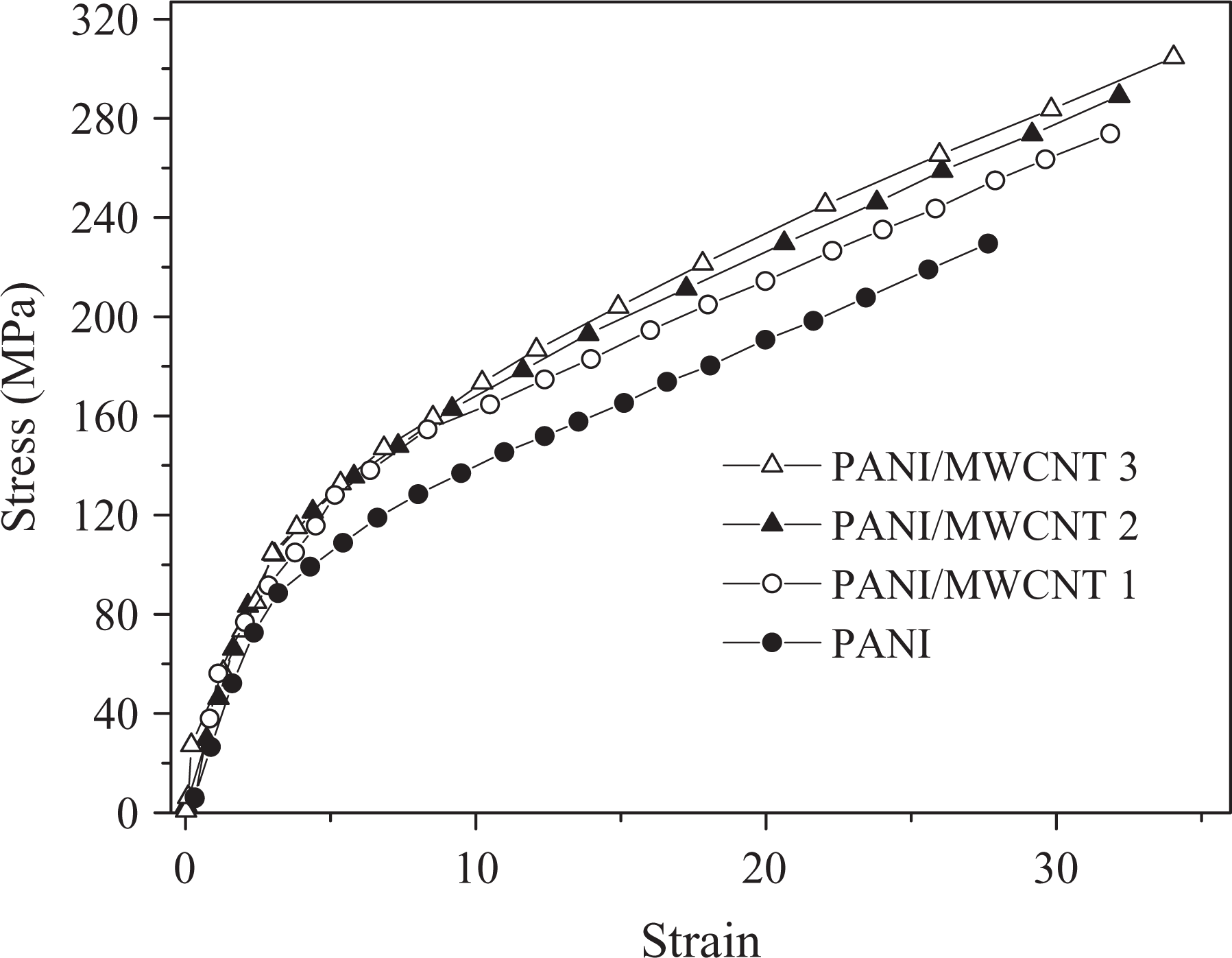
Stress–strain curves of neat PANI and PANI/MWCNT films. PANI: poly(azo-naphthyl-imide); MWCNT: multi-walled carbon nanotube.
Tensile properties of pristine PANI, PANI nanofiber, and PANI/MWCNT nanofiber-reinforced films.
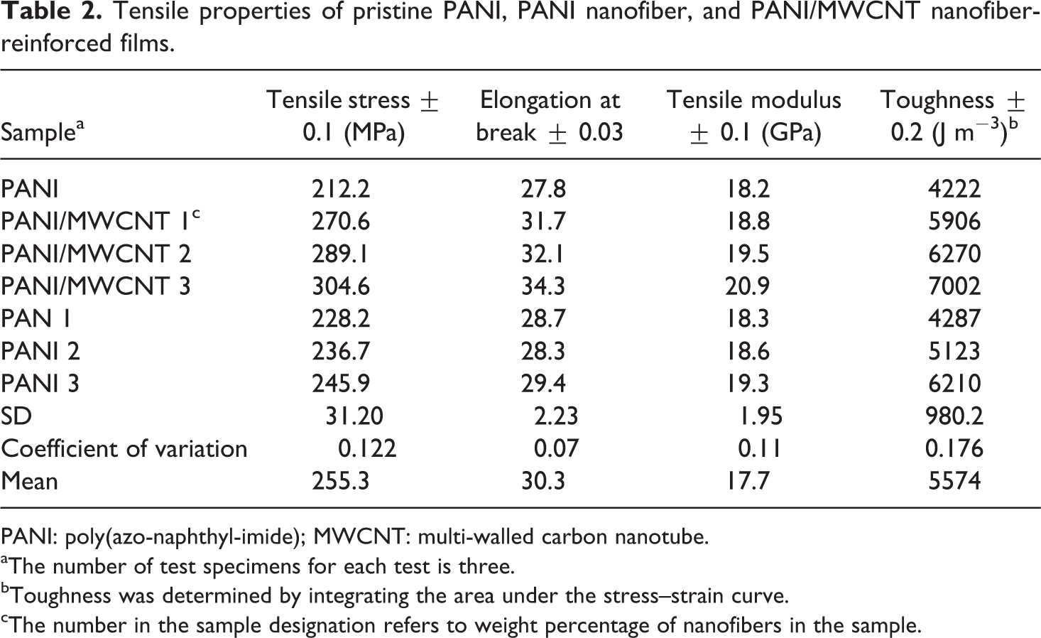
PANI: poly(azo-naphthyl-imide); MWCNT: multi-walled carbon nanotube.
aThe number of test specimens for each test is three.
bToughness was determined by integrating the area under the stress–strain curve.
cThe number in the sample designation refers to weight percentage of nanofibers in the sample.

Poly(azo-naphthyl-imide)/multi-walled nanotube fibers.
Morphology
Optimum experimental parameters such as the polymer solution properties (viscosity) and electrospinning conditions (e.g. voltage, spinneret–collector distance) resulted nanofibers with smaller diameters. Figure 5(a) showed that the PANI/MWCNT nanofibers collected by spinning method were reasonably aligned. On the other hand, Figure 5(b) revealed that the as-prepared PANI nanofibers were not well homogeneous and oriented as that of electrospun PANI/MWCNT nanofibers. The electrospun PANI/MWCNT nanofibers were comparatively smooth, uniformly aligned, and almost free of defects. Generally, the diameter uniformity in the electrospun nanofibers is of essential importance for achieving high strength and toughness. Electrospinning of PANI/MWCNT-PAA solution and subsequent imidization, PANI nanofibers with MWCNT were prepared. Figure 5(c) and (d) shows the micrographs with various wt% of PANI/MWCNT nanofibers. It can be seen that the diameter of the nanofibers containing 3 wt% PANI/MWCNT (Figure 5(e) was greater as that of 1 wt% PANI/MWCNT. The incorporation of greater wt% PANI/MWCNT, therefore, led to the widening of the diameter distribution due to wrapping of the matrix. Figure 6(a) and (b) shows the TEM micrographs of the electrospun PANI nanofiber and PANI nanofiber containing MWCNT. After the imidization the poly(amic acid) chains formed a coating layer around each individual MWCNT rope due to hydrogen bonding and keep the nanotubes from aggregating or bundling together, and thus the MWCNT were well dispersed in the electrospun nanofibers (Figure 6(a)). The surface of PANI nanofiber (Figure 6(b)) was found to be less smooth compared with PANI nanofiber-containing MWCNT. It seemed that the inclusion of CNTs render fine alignment to the nanofibers compared with neat PANI nanofibers.
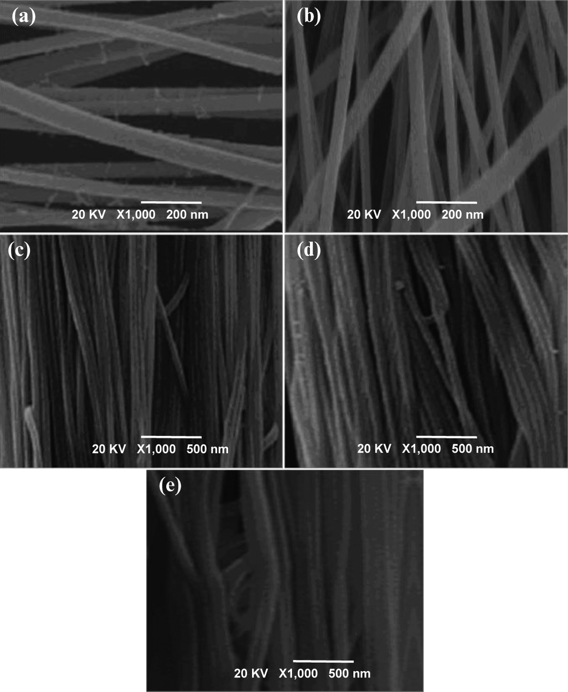
FESEM images of (a) PANI/MWCNT nanofibers; (b) PANI nanofibers; (c) PANI/MWCNT 1 film; (d) PANI/MWCNT 2 film; (e) PANI/MWCNT 3 film. FESEM: field-emission scanning electron microscopy; PANI: poly(azo-naphthyl-imide); MWCNT: multi-walled carbon nanotube.
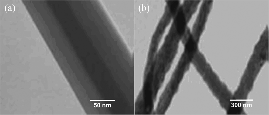
TEM images of (a) PANI/MWCNT nanofibers and (b) PANI nanofibers. TEM: transmission electron microscopy; PANI: poly(azo-naphthyl-imide); MWCNT: multi-walled carbon nanotube.
Thermal properties
TGA data and thermograms for neat PANI and different nanofiber-reinforced PANI films are shown in Table 3 and Figure 7. Results revealed that the PANI films reinforced by PANI/MWCNT electrospun nanofibers possessed excellent thermal stability. In the case of neat PANI, initial degradation temperature (T0) of 552°C, 10% weight loss temperature (T10) of 581°C, and maximum temperature (Tmax) of 615°C was observed. Inclusion of 1 wt% PANI/MWCNT nanofibers resulted in T0 of 565°C, T10 of 599°C, and Tmax of 634°C. 2 wt% PANI/MWCNT compatiblized with the polymer matrix resulted in T0 of 582°C, T10 of 610°C, and Tmax of 646°C. Moreover, inclusion of 3 wt% PANI/MWCNT nanofibers consequenced T0 of 589°C, T10 of 625°C, and Tmax of 666°C was obtained. However, the stability was noticeably lower for PANI nanofiber-based system. PANI 1–3 showed T0 of 554–569°C, T10 of 584–594 C, and Tmax of 621–642°C. Besides, the char yield of the PANI/MWCNT nanohybrids was suitably higher, that is, 38–48% at 700°C. On the contrary, char yield of PANI nanofiber hybrids was 36–41%. The glass transition temperature (Tg) of the nanocomposite films was investigated using loss tangent (tan δ) of dynamic mechanical analysis. As shown in Figure 8, tan δ of the PANI/MWCNT showed increased segmental Tg. With increasing the amount of PANI/MWCNT nanofiber in system, the Tg was shifted from 243 to 261°C. The increase in the segmental rigidity was attributed to the restriction of chains bonded to CNTs. In the case of PANI-based system, Tg was only raised to 239–241°C. In general, the incorporation of MWCNT may lead to the increase of Tg of polymer. The material containing 3 wt% PANI/MWCNT nanofibers possessed higher tan δ and Tg, indicating that the film had the greater rigidity. The homogeneity self-reinforcing method was quite successful for fabricating the high-performance polyimide nanocomposites relative to reported ones. 26,29
Thermal analyses data of pristine PANI, PANI nanofibers, and PANI/MWCNT nanofiber-reinforced films.
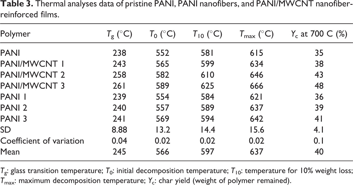
Tg: glass transition temperature; T0: initial decomposition temperature; T10: temperature for 10% weight loss; Tmax: maximum decomposition temperature; Yc: char yield (weight of polymer remained).
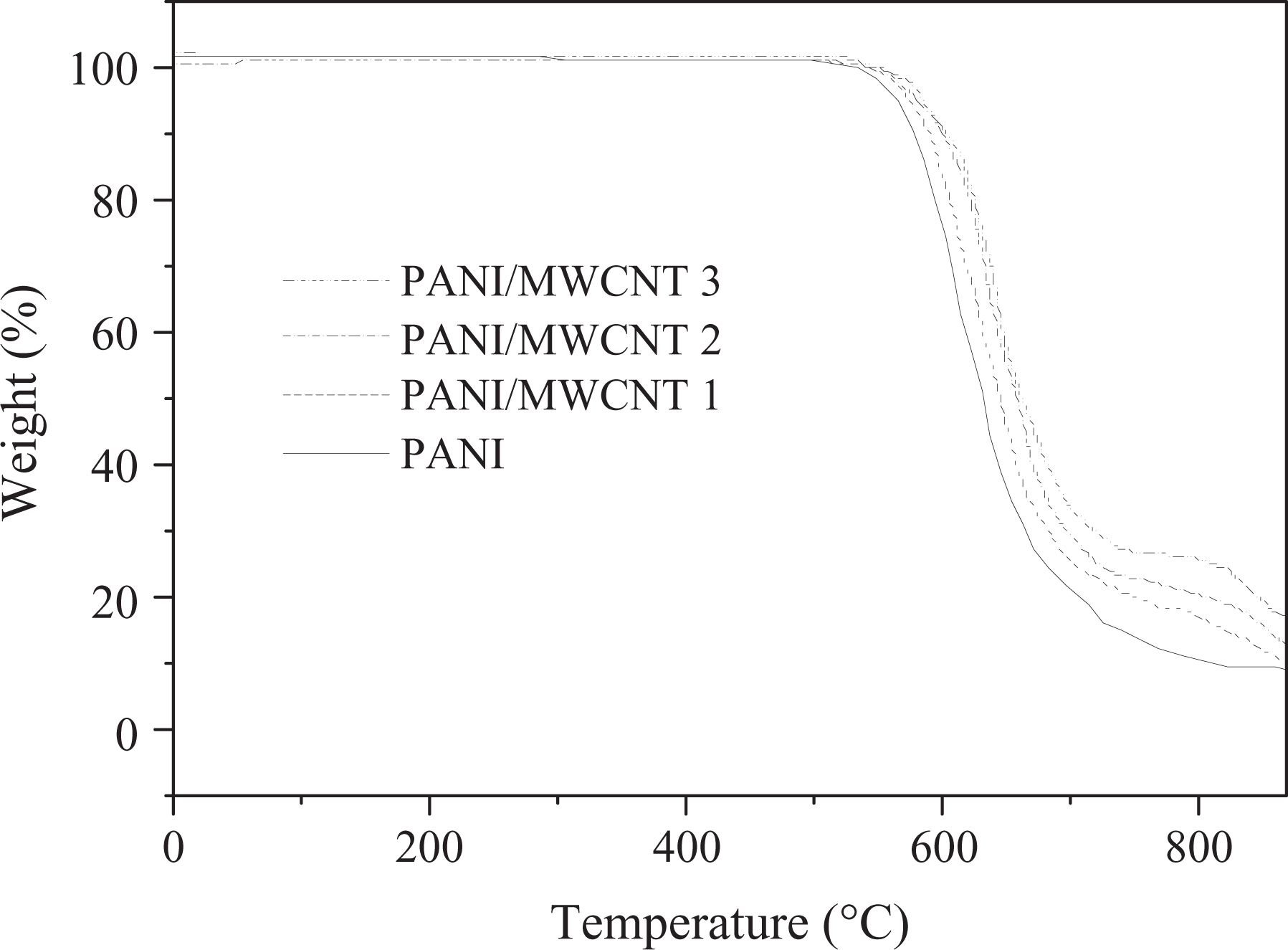
TGA curves of neat PANI and PANI/MWCNT films at a heating rate 10°C min−1 under N2 atmosphere. TGA: thermogravimetric analysis; PANI: poly(azo-naphthyl-imide); MWCNT: multi-walled carbon nanotube.
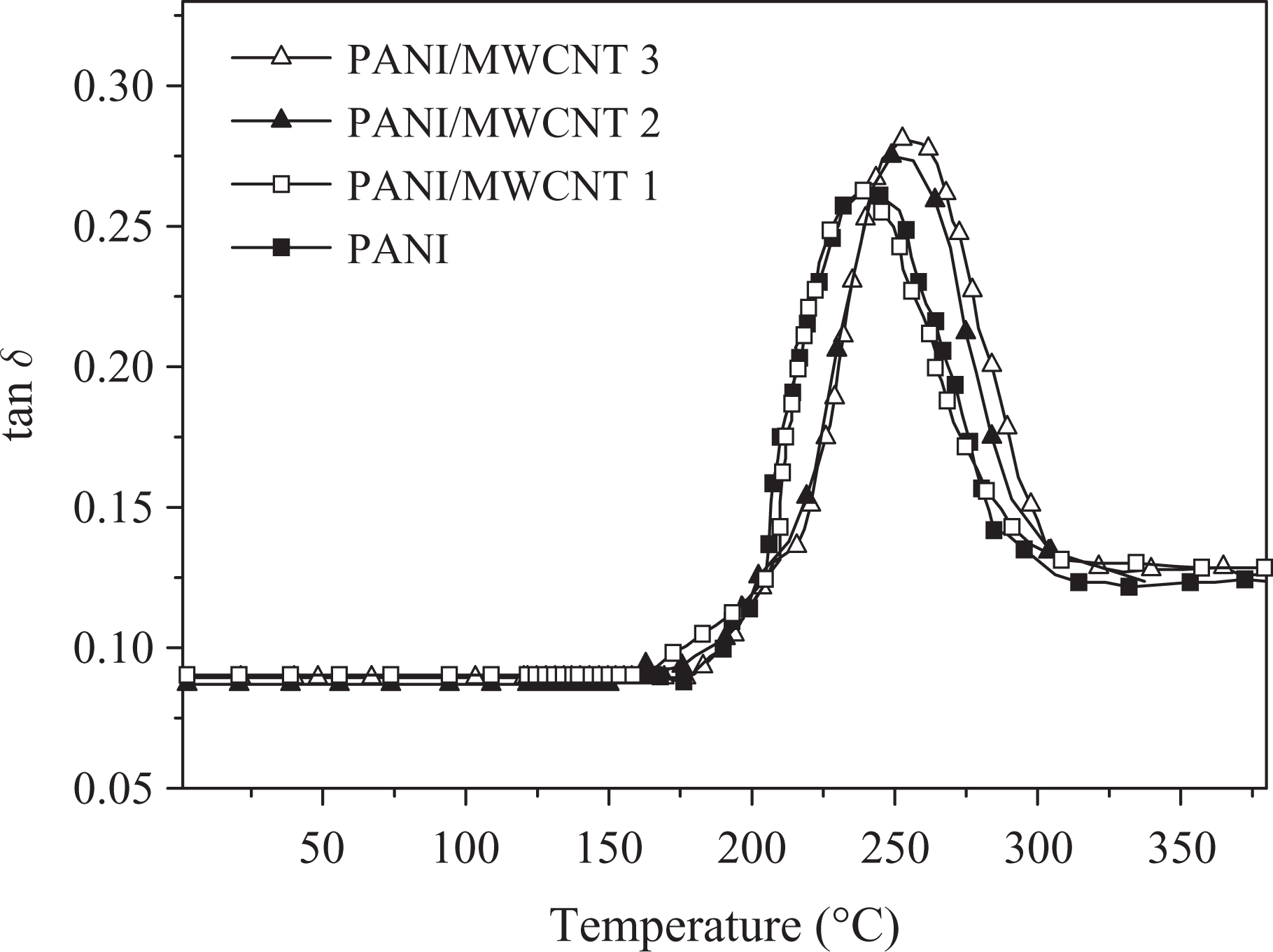
Variation of loss tangent (tan δ) with temperature for pure polymer and PANI/MWCNT films. PANI: poly(azo-naphthyl-imide); MWCNT: multi-walled carbon nanotube.
Conclusion
Both pure polyimide and MWCNT-reinforced PANI nanocomposite fibers were produced by electrospinning, in this study. Afterward, high-performance polyimide nanocomposite films were fabricated by self-reinforcing technique with a loading of as-prepared 1, 3, and 5 wt% nanofibers. FESEM and TEM micrographs indicated that the PANI/MWCNT were homogeneously dispersed and well oriented in the nanofibers. The study revealed that the as-prepared PANI/MWCNT aligned electrospun nanofibers were ideal self-reinforcing agents to fabricate high-performance nanocomposite films because of good compatibility between the electrospun nanofibers and the matrix. Newly developed PANI nanofibers were efficient load-transferring materials from the matrix to nanofibers. As a consequence, the tensile properties of films have been remarkably improved by incorporating the aligned neat PANI fibers and PANI/MWCNT nanofibers. Quite interestingly, the electrospun nanofibers not only improved the tensile strength but also the tensile strain at break of polyimide films. Compared with PANI nanofibers-reinforced films, the tensile strength, tensile modulus, and elongation at break for the PANI/MWCNT nanocomposite were found to be superior. The as-prepared high-performance nanocomposite films also showed enhanced thermal properties after the incorporation of nanofibers relative to pristine PANI. Likewise, the thermal stability of PANI/MWCNT nanofiber films was sufficiently higher relative to neat PANI and nanocomposite series. Self-reinforcement approach to fabricate PANI/MWCNT nanofiber films was, thus, a fine attempt to utilize MWCNT to attain tough and light-weight material for defense and aerospace purposes.
Footnotes
Declaration of Conflicting Interests
The author(s) declared no potential conflicts of interest with respect to the research, authorship, and/or publication of this article.
Funding
The author(s) received no financial support for the research, authorship, and/or publication of this article.