
Abstract
Nanofiber membranes are extensively used in ultra- and micro-filtration purposes due to their high surface-to-volume ratio. However, nanofiber membranes do not have adequate strength to withstand forces acting on the filter surface, especially when using very low porosity membranes. In this study, PVC nanofiber mats and nanofiber composite membranes were fabricated through electrospinning and solvent casting technology. The membranes were characterized using scanning electron microscopy (SEM), porosimetry, and tensile strength tests. Analysis indicated that electrospun mats contain varying pore sizes (nano to micro) whose frequencies within the mat vary with fiber diameter. It was also established that mats fabricated from low solution concentration contain the largest percentage of pores. The mats’ tensile strength varied with fiber packing density, fiber assembly, and the density of fiber-to-fiber contact points. The tensile properties of the nanofiber composite membranes were found to be between those of the constituents and changed with change in the nanofiber layer thickness. The fabricated nanofiber composite membranes are intended for use in applications such as air ultra-filtration, acoustic filtration etc. The high porosity and small mesh pore size of electrospun nanofiber mats allow for removal of ultra-fine particles or microbes from contaminated air, water or other media.
Introduction
Electrospinning is a major technique for the production of high specific surface area and high porosity nanofiber membranes from most polymers. The technique is of a lot of interest with regards to the uniqueness of the properties of the membranes and the wide variety of materials that can be handled.1–3 Many studies have been done focusing on the development of functional nanofibers and nanofiber-based nanofiber composites whose applications offer new technology and business opportunities for several sectors.4,5 Electrospun nanofiber membranes have been applied in composite reinforcements, 6 media filtration, 7 enzyme immobilization, 8 energy catalysis, 9 sensors, 10 tissue scaffolds, 11 wound dressing 12 and drug delivery 13 etc. In particular, use of nanofibers has had the most interest in filtration where in a typical setup, sieve effect filters out large particles on the filter surface while particles smaller than the surface-pores penetrate into the filter and get captured by interception, impaction, or static electrical attraction with the nanofibers.14,15 Sundarrajan et al. 15 explained that nanofibers capture tiny particles in an air stream through Brownian diffusion and interception. Membranes with the smallest fiber diameters have the highest filtration efficiencies for obvious reasons. 16 A downside of electrospun nanofiber mats in filtration is their insufficient mechanical strength. Thus, in order to exploit the unique properties of the nanofibers, backing mechanisms have been employed to enhance strength. 17 Many methods that have been put forward for reinforcement have been said to either interfere with the highly porous nature of the nanofiber membranes or complicate the electrospinning process. 18 Strength reinforcement of electrospun nanofiber mats has been classified into three, yarn fabrication from electrospun fibers, use of reinforcement material and welding fibers at junctions. 19 In a liquid filtration study, Homaeigohar et al. 20 prepared and evaluated the properties of a nanofibrous composite constituting electrospun polyethersulfone nanofiber mat and poly(ethylene terephthalate) non-woven backing and used heat treatment to enhance integration. Chemical modification has also been proposed for the improvement of mechanical properties of polymeric nanofiber mats. Huang et al. 18 reported on the use of polydopamine to promote bonding by coating the fiber junction points resulting in 100–300% increase in tensile strength and Young’s Modulus. Grkovic et al. 21 demonstrated that significant improvement of mechanical properties of electrospun nanofiber membranes could be attained via crosslinking of chitosan/poly(ethylene oxide) and citric acid whereby crosslinks occur due to formation of ester, hydrogen and peptide bonds. Another study demonstrated the enhancement of mechanical strength of electrospun polyacrylonitrile – poly(vinyl chloride) (PVC) nanofiber mats by welding the fibers at junction points and reinforcing with multi-walled carbon nanotubes for pressure-driven particulate water filtration. 19 Up to 314% increase in tensile strength was achieved.
PVC is one of the majorly used thermoplastic industrial polymers with wide applications in packaging, construction, plumbing, electrical appliances, textiles, car door panels etc. due to its advantageous physical and mechanical properties during product fabrication and application. Among its various advantages for industrial application include easy workability, low-cost, high tensile strength, dimensional stability as well as being a relatively dense polymer. 22 Virgin PVC is rigid and brittle but can be made flexible to varying degrees using plasticizers such as dioctyl phthalate. The use of plasticizers however can be limited since they compromise PVC’s inherent tensile strength and chemical resistance. Susceptibility of pure PVC to rapid degradation under heat and sunlight requires the use of stabilizers during heat processing and outdoor applications.23,24 An important advantage of PVC especially in solvent processing is its solubility in a wide range of solvents that include tetrahydrofuran (THF), cyclohexanone cyclopentanone, dimethylformamide (DMF) 25 etc. As such, the polymer has been electrospun successfully using some of these solvents where the properties of the nanofiber mats have been reported to be subject to type of solvent, solution properties, and process settings.26–29 Investigations on the use of PVC nanofibers in nonwoven form have shown that they possess excellent filtration properties and reach sufficiently high filtration efficiencies.30,31
In light of the advantages of the electrospinning process and the unique properties of electrospun nanofibers, this study aims to demonstrate the development of a PVC nanofiber composite membrane having adequate mechanical properties for particular filtration applications. The morphology, tensile strength, and porosity of a nanofiber composite are investigated.
Material and methods
Materials
Chemical resources used in this study were PVC (Mn 47,000), tetrahydrofuran (THF, AR grade, >99.9% purity) and N,N-dimethylformamide (DMF, AR grade, >99.8% purity). All chemicals were purchased from Sigma-Aldrich (USA) and were used without further purification.
Solution and nanofiber mat preparation
Electrospinning and solvent casting solutions were prepared using a 1:1 (w/w) DMF/THF solvent mixtures. A magnetic stirrer was used to stir the solutions for 6 h before electrospinning or film preparation. The electrospinning was done on a vertical single nozzle setup as shown in Figure 1 with a variable high DC voltage power supply at constant voltage of 20 kV, constant flow rate and 20 cm distance between an aluminium collector and spinneret tip. Standard conditions of 68% RH and 22°C were used.
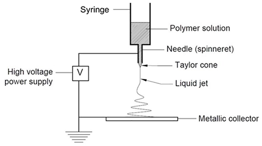
Electrospinning setup.
Micro-thickness PVC film casting
Micro-thickness films were prepared using a simple solvent casting technique that involved applying and uniformly pressing polymer solutions of known mass between two glass plates and then gently and uniformly sliding them in opposite directions, eventually separating them to achieve uniform films on their surfaces. The glass plates containing the polymer films were then kept at room temperature for 24 hours to allow for gradual evaporation of the solvents. Uniform micron thickness dry films were obtained and peeled off the glass surfaces. The thickness of the films was determined from SEM micrographs.
Nanofiber composite preparation
Nanofiber composite films were prepared by placing a weighed nanofiber mat between two dry micro-thickness films. This layered arrangement was placed between two glass plates and then heated uniformly while applying uniform pressure to make the nanofiber mat and micro-thickness films adhere to each other. It was then left to cool down before carefully removing the nanofiber composite. Figure 2 shows the solution concentrations used and the tests performed for the final products. Regression analysis was used to determine the correlations between solution concentration and nanofiber tensile strength. Analysis of variance (ANOVA) was used to determine variations between the tensile strengths of the nanofiber mats and PVC cast film.

Experimental plan for nanofiber mat and nanofiber composite fabrication and tests.
Characterization
The morphologies of adequately prepared samples of the fabricated mats and films were viewed using a scanning electron microscope (SEM) (JEOL JSM – 5300) at 20 kV and 15 kV acceleration voltage for the nanofibers and the nanofiber composite respectively. Adobe Acrobat Pro DC software was used to determine nanofiber and nanofiber composite dimensions from the SEM micrographs. Nanofiber mats, micro-thickness films and nanofiber composite films samples measuring 60 mm × 10 mm were used to perform the tensile strength tests. For better handling, the nanofiber mats were folded four times to form the test sample. Sample holders as shown in Figure 3 were made from two cardboard frames which had double sided adhesive tapes to attach the nanofiber mats. Tests were performed at a clamp speed of 50 mm/min, a gauge length of 40 mm and using a load cell of 100 N.


Tensile test sample clamping for testing.
Results and discussion
The fabricated nanofiber composite described in this study can potentially be used in ultra-filtration masks for the removal of bacteria, viruses or noxious compounds or applied in noise absorption media as shown in Figure 4. It is well understood that nanofiber mats have generally low mechanical strength and by themselves cannot withstand forces acting on the filter surface as a result of pressure difference of the air stream, especially with very low porosity nanofiber mats. 18 Nanofiber mat surface and internal geometries (fiber diameter and mat porosity) have been found to significantly affect membrane efficiency in ultra-filtration and noise absorption.

Schematic application of the nanofiber composite in: (a) ultrafiltration cell and (b) sound absorption cell.
Morphological properties
Nanofiber mat
The surface morphology of PVC nanofiber mat was observed by SEM. Figure 5 illustrates the surface appearances of PVC nanofibers at different solution concentrations.

SEM of PVC nanofiber mats at: (a) 12%, (b) 14%, and (c) 16% solution concentration and their corresponding fiber diameter distributions and average fiber diameters.
For any electrospun nanofiber mat, the geometrical properties of the nanofibers are influenced by solution concentration and the electrospinning conditions. Lower solution concentrations yield thinner fibers containing beads that are randomly distributed along their lengths while thicker fibers with reducing bead content are obtained as solution concentration is increased. As shown in Figure 5, electrospinning at 12 wt.% PVC resulted in presence of beads along the lengths of the nanofibers. Electrospinning at 14 wt.% and 16 wt.% solutions resulted in smooth but thicker nanofibers. The increase in fiber diameter and diameter uniformity with the increase in solution concentration, other factors constant, is as a result of the gradually increasing viscoelastic force which limits the stretching effect of the electrostatic and columbic repulsion forces.33–35
Nanofiber composite film
Nanofiber composite prepared by the mentioned method is a sandwich of nanofiber mat between two micro-thickness films. The film thickness used in this work was constant while the total nanofiber composite thickness depended on the thickness of the nanofiber mat. Several nanofiber composites of different thicknesses were prepared to study the effect of mat thickness on the nanofiber composite strength. Figure 6 illustrates the nanofiber composite structure.
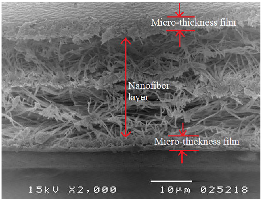
SEM micrograph of the nanofiber composite cross-section.
The SEM micrographs of the edges of the nanofiber composites indicates good interfacial adhesion between the micro-thickness film and the nanofiber layer. The nanofiber layer also appears to have different layers within its structure. These discontinuous multi-layers within an electrospun nanofiber mat have been reported to result in alteration of the mats porosity which varies depending on the conditions of electrospinning and solution properties. 36 This indicates that several different specific porosities and varying pore sizes can be present within the same nanofiber mat as has been established before where pore diameters frequency distribution can be divided into a nano-zone with pore diameters less than 100 nm and a micro-zone whose pore diameters are over 100 nm. 37 It has been supposed that the micro-pores would most likely occur closer to the mat’s surface while the nano-pores would be located deeper in the mat; their frequencies being dictated by the fiber collection method and fiber diameter.37,38 As seen in Figure 6, the structural geometry of the nanofiber mat shows several discontinuous layers whose individual pore sizes are large and depends on the electrospinning conditions, solution properties and fiber orientation. The overall mat’s pore diameter should be lower due to the multiple layers in the structure hence different distributions of pore sizes in the nano and micro zones. The continuity of the open pores through the different layers would be of importance especially in acoustic applications since they provide increased sound absorption efficiency. It has been explained that sound energy absorption by nonwovens is influenced by pore diameters, inter-pore space, fiber flexibility as well as the angle of incidence of the sound wave and its resonance frequency. 39 As already established and generally well understood, electrospun nanofiber mats have high surface area to volume ratios and relatively high porosities and pore sizes and densities that are dependent on fiber diameter and fiber distribution in the different layers.37,38 Figure 7 illustrates the frequency of pore sizes in the electrospun nanofiber mat that was sandwiched between the micro-thickness films.

Frequency distribution of pore diameters in electrospun nanofiber mat.
From the experimental results, it was concluded that low polymer concentration during electrospining resulted in nanofiber mats having the highest percentage of nano-pores due to their smaller fiber diameter sizes and therefore, they would posses a higher number of layers forming the mat for the same mat weight. This analysis supports the use of fine spinnerets and electrospinning conditions that favour production of finer fibers so as to yield maximum nano-pores in the mat.
Mechanical properties
Nanofiber mats
Table 1 shows the tensile strength values of the nanofiber mats and cast micro-thickness film at different solution concentrations. It indicates that increasing the solution concentration of the nanofiber mats resulted in an increase in tensile strength of the nanofiber mats. This has been attributed to the reduction in number of beads with increase in solution concentration. Presence of beads in the nanofiber mats reduces the number of fiber contact points per unit volume and as solution concentration is increased, smoother fibers with improved diameter uniformity are formed thus increased fiber cohesion points, hence, increase in the tensile strength. Electrospun nanofiber mats break due to failure of fiber cohesion points and not due to breakage of individual fibers. 34
Cast micro-thickness film and nanofiber mats tensile strengths for different polymer concentration %.

Mechanical properties of nanofiber mats in many instances do not meet the requirements of most applications and require some sort of reinforcement or treatment on the nanofibers to make them survive installation conditions and improve performance and durability. 40 Generally, the tensile behaviour of the mats is dictated by the fiber morphology as well as the fiber orientation and number of contact points between fibers in the mat. Rupturing of inter-fiber junction points marks the start of mat failure and any deformation experienced by the mat is unrecoverable.28,34 Figure 8 shows a strip of a nanofiber mat under uniaxial load. The nanofiber mat exhibits high tensile elongation accompanied by significant reduction in the specimen width. This behaviour results in the nanofiber mat experiencing varying stresses even under constant loads during application. Furthermore, the high elongation due to small loads could cause significant changes in the mat’s physical properties (porosity, pore sizes, and pore distribution) which would then alter the mats expected functional performance. Therefore, for optimum performance of nanofiber mats, any reinforcement or treatment applied to improve mechanical properties should minimize the high unrecoverable tensile elongations without altering the mat’s physical properties.
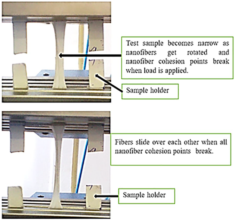
Nanofiber mat under uniaxial loading.
The stress–strain curve illustrated in Figure 9 shows the tensile behaviour of the nanofiber mat under uniform loading. The high tensile elongation is evident as well as the presence of a high modulus and a low modulus region on the plot as has been previously described for randomly aligned nanofiber mats. 29 The high modulus region indicates the breaking of adhesion points between the nanofibers upon application of tensile load while the low modulus region indicates when the nanofibers are sliding over each other after the adhesion points have all been severed.
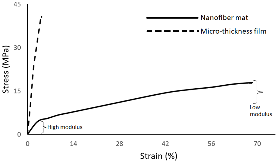
Stress–strain curves for nanofiber mat and cast micro-thickness film.
Cast micro-thickness film
In this study, the effect of varying solution concentration on the tensile strength of the micro thickness films was found not to be significant as shown in the ANOVA in Table 2. This was attributed to the slow rate of solvent evaporation from the films. The solvent evaporation rate allowed some time for the chains to relax into lower energy states, hence, cancelling out some of the chain conformations present in solution form.
ANOVA of tensile strengths of 12%, 14% and 16% PVC micro thickness films.

Tensile tests performed on the solvent cast micro-thickness films indicated that they have higher tensile strength and modulus but low elongations at break as shown in Figure 9 compared to the nanofiber mats. These differences were attributed to their different structures which result from the different technologies used in fabrication. For polymer films, the material’s tensile behaviour is mainly influenced by the physical properties of the polymer, as well as the molecular chain arrangement whereas for randomly oriented nanofiber mats, tensile behaviour greatly rely on fiber morphology 34 whereby the mats may fail without maximum utilization of the polymer’s strength.
When load is applied on solvent cast polymer films, the load is directly borne by the bulk of the film, hence, stress and young’s modulus will be influenced by molecular chain orientations, inter-chain interactions and the degree of crystallinity. During preparation of cast micro thickness film using organic solvents, evaporation of the solvent leads to an increase in polymer concentration, inter diffusion of polymeric chains and eventually the formation of a solvent free film. 41 The solvent’s interaction with polymer molecules in solution form and during the start of film formation is critical in that the effects from certain conformations of the polymer chain could carry on into the cast film. Furthermore, the type of solvent and solvent mixtures used in solution preparation have been shown to influence physical properties of solvent cast polymer films. 42 Different solvents differ in the way they affect the conformation of polymer molecules in solution, which may have an effect on the ultimate mechanical properties and physical properties of a polymer film. The solution concentration may also have an effect on the film’s mechanical properties. When the solution concentration is increased for a given polymer, molecule inter-chain interactions increase due to the decreased average distance between chains. These interactions can then persist into the dried film when the solution is cast, 43 and may result in an increase in mechanical strength of the films with increase in solution concentration. Nevertheless, the starting polymer concentration has also been found to influence cast film degree of crystallinity, whereby low to moderate concentrations can result in an increase in crystallinity, hence improved mechanical properties, while higher concentrations would impede crystallization during casting. Film crystallinity increases at lower concentrations because there is adequate space between chains for easy mobility but at high concentrations, overlapping and entanglement of polymer chains occurs, thus interrupting chain mobility and crystallization. 44 Another factor that could affect cast film properties is the rate of solvent evaporation. Rapid solvent evaporation during casting causes the polymer chains in solution to “freeze” in their solvent induced form, hence, some of the physical conformations present in the solution end up in the dry film. 45 Slow solvent evaporation, however, may result in films from different solution concentrations having insignificantly different mechanical properties.
Nanofiber mats to cast film tensile strength ratios
The tensile strength of nanofiber mats is dependent on a number of factors which include, fiber diameter, fiber surface properties, fiber length, individual fiber strength, fiber orientation within the mat structure and the fiber interfacial forces. The number of inter-fiber contact points in a fibrous mat is dependent on fiber length, fiber diameter, and the fiber packing density. 37 As per the failure mechanism of randomly oriented nanofiber mats, the mats’ strength should be proportional to the number of contacts per unit volume in the fiber assembly. Definitely, mats composed of thinner non-beaded fibers should have more inter-fiber contact points per unit volume and for electrospun nanofiber mats, the packing density will thus, become a function of electrospinning process parameters and solution properties. The ratio of nanofiber mats to solvent cast micro-thickness films tensile strength can then be used identify the micro structure of the nanofiber mat. 46 Figure 10 shows the plot of nanofiber mat to micro-thickness film tensile strength ratios against nanofiber diameter. The effect of lack of beads and consistent nanofiber diameter on the mat’s tensile strength is evident where increase in fiber diameter (corresponding to increase in solution concentration) results in an increase in tensile strength ratio. Consistent adhesion forces at the inter-fiber junction points due to reduced diameter unevenness of the randomly laid nanofibers in the mat is one of the causes of increase in the strength ratio.

Nanofiber mat to film tensile strength ratios versus nanofiber diameter.
Nanofiber composite
Figure 11 shows the stress–strain curve of the PVC nanofiber composite and its image after failure due to tensile loading. The nanofiber composite exhibits tensile elongation that is lower than that of the nanofiber mat but significantly higher than that of a plain cast film. Furthermore, there is a lower reduction in the specimen’s width with load application. From the results, the nanofiber composite films had specific tensile strength values that were higher than those of the nanofiber mats, but lower than those of the micro thickness films.

Stress–strain curve of PVC nanofiber composite and the corresponding image of ruptured tensile test film.
As observed, the stress–strain curves of the nanofiber composite films exhibited a two-step shape; a plateau after the yield point followed by a sharp drop and then another plateau before the film failed. Additionally, the nanofiber composite films had a high tensile modulus and a large elongation; properties that did not exist together in the plain nanofiber mat or the plain cast film. The dropping plateau shape was attributed to the different tensile behaviours and structures of the components of the nanofiber composite film. Furthermore, the effect of the heating process during nanofiber composite formation may have resulted in the molecules in the cast film to relax as well as in some light inter-fiber fusions in the nanofiber mat. The micro-thickness film part of the nanocomposite was majorly responsible for the linear elastic deformation region of the curve. The initial plateau was also mainly due to plastic deformation of the micro-thickness film. The start of the second plateau of the curve was attributed to the severance of the nanofiber fusion points and the realignment of the nanofibers in the load direction as the nanocomposite headed toward complete failure. The overall effect was the high modulus of the nanofiber composite and its relatively large strain.
Using the rule of mixtures as shown in


Where;
σ- tensile strength
G – basis weight of the nanofiber mat in g/m2
t – thickness of the nanofiber mat
Vmat – volume of nanofiber mat
Vfilm – volume of film
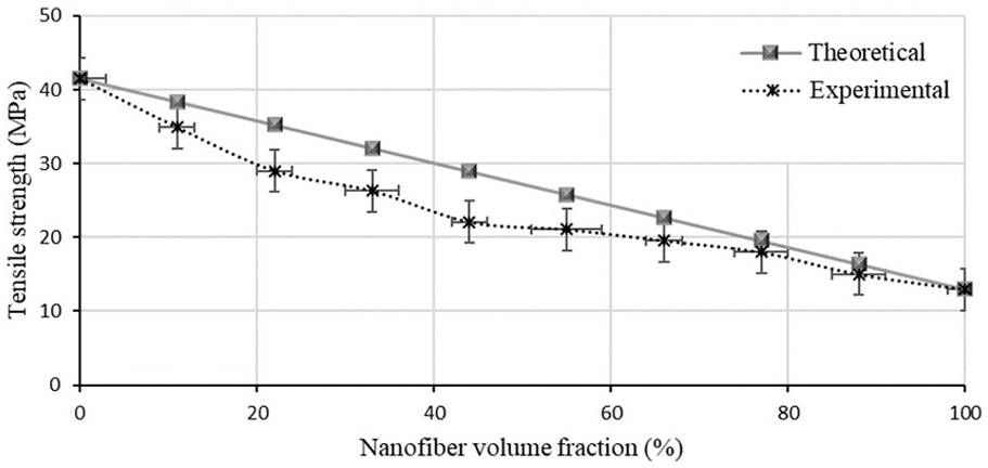
Experimental and theoretical tensile strength values of the nanofiber composite versus the nanofiber mat volume fraction.
Varying the proportion of the nanofiber mat in the nanofiber composite had a significant effect on its tensile strength. This is because it led to a change in the volume fraction of the nanofiber mat which in turn resulted in a direct variation in the thickness of the nanofiber composite. The suggested nanofiber composite design can be applied in several applications without being limited by the constituents’ mechanical properties and the nanofiber mat volume fraction can be determined as per the requirements of the end use.
Conclusion
In this study, a method of developing a nanofiber composite is given. The fabrication of micro-thickness PVC films is achieved through solvent casting. Change of solution concentration from 12 wt.% to 16 wt.% does not have a significant effect on the tensile strength of the solvent cast films. The tensile strength of electrospun nanofiber mats is affected by the nanofiber assembly and density of fiber contact points. Unlike the nanofiber mats, nanofiber composite films have significantly lower elongation and failure occurs when the sample breaks at one point of the sample. The frequency of nano- and micro-pores within a nanofiber mat is dependent upon the fiber diameter and orientation within the mat. Varying the volume fraction of the nanofiber mat in nanofiber composite has a significant effect on its tensile strength and can be determined as dictated by the end use.
Footnotes
Declaration of conflicting interests
The author(s) declared no potential conflicts of interest with respect to the research, authorship, and/or publication of this article.
Funding
The author(s) received no financial support for the research, authorship, and/or publication of this article.