
Abstract
Polypropylene/polycarbonate (PP/PC), PP/poly(styrene-b-(ethylene-co-butylene)-b-styrene) (PP/SEBS) binary blends, and PP/PC/SEBS ternary blend were produced via melt blending in a co-rotating twin-screw extruder. The phase morphology, tensile, and impact behaviors of the blends were studied. Transmission optical microscopy and atomic force microscopy investigations of the necking region in tensile tests and scanning electron microscopy of tensile fractured surfaces were performed to characterize the fracture mechanism. In the PP/PC/SEBS ternary blend, core–shell morphology (PC particles as a core and the SEBS phase as a shell) was formed. Analysis of micromechanical deformation suggested that crazing occurred in PP and shear yielding did not occur during tensile tests. Rubber particles cavitation, shear yielding, and crazing occurred in both the PP/SEBS binary blend and PP/PC/SEBS ternary blend. Results showed that Corté and Leibler’s theory was unable to describe the effect of core–shell particles in these blends.
Introduction
Toughening of semicrystalline polymers continues to be an active area of research and development. The mechanisms by which polymer materials are toughened have been widely studied. Although several methods have been adopted to toughen semicrystalline polymers, the most efficient and successful way has been to incorporate a dispersed rubbery phase within the semicrystalline matrix. It has long been known that the toughness and the deformation mechanism of rubber-toughened polymers are strongly dependent upon the size and substructure of the dispersed rubber modifier.
1
Wu found that toughening can only be achieved below a critical interparticle ligament thickness (LC) that is generally considered as an intrinsic property of the matrix, independent of the size and nature of particles.
2
However, many studies showed that the nature of the matrix, the morphology of the dispersed phase (i.e., rubber particle size and its distribution), rubber content, and processing conditions are important factors that determine the level of toughening.
3
–6
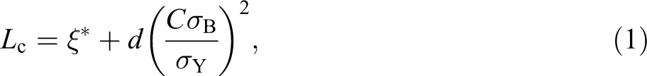
Recently, Corté and Leibler proposed a different model for semicrystalline polymers toughened by rubber particles based on two competing processes of matrix shear yielding activated by the particles and of brittle fracture caused by coalescence of microcracks between crystalline lamellae. They showed that for successful toughening, the interparticle distance (L) should be smaller than a critical length LC, which is given by
In this study, PP/PC/SEBS ternary blend, PP/PC, and PP/SEBS binary blends were fabricated to investigate the effects of core–shell particles on the tensile behavior and deformation mechanism of PP/PC/SEBS ternary blend. Tensile and Izod impact tests were performed to measure the mechanical property, and then, fracture mechanisms were characterized by transmission optical microscopy (TOM), atomic force microscope (AFM), and scanning electron microscopy (SEM). The model of Corté and Liebler was investigated to describe the differential toughening effect between blends containing individual rubber particles and blends containing core–shell particles.
Materials and methods
Materials
These materials were used for blending (i) an isotactic polypropylene homopolymer SEETEC H5300 (melt flow index (MFI): 3.5 g/10 min, 230°C, 2.16 kg) supplied by LG Chemical Co. (Korea); (ii) polycarbonate, Makrolon 2858 (MFI: 10 g/10 min, 300°C, 1.2 kg) supplied by Bayer Co. (Germany); (iii) SEBS, Kraton G1652 (29% styrene; molecular weight; styrene block 7000, EB block 37500), supplied by Shell Chemicals Co. (USA); (iv) SEBS-g-maleic anhydride (MAH), Kraton FG1901x (29% styrene; nominal weight percentage of grafted MAH: 1.8 ± 0.4%) supplied by Shell Chemicals Co. (USA).
Blend preparation
Blends were prepared via melt blending in a co-rotating twin-screw extruder (diameter of screw = 2 cm, length/diameter ratio = 40) as described in Jazani et al. 9 Before processing, the materials were oven-dried for at least 17 h at 80°C. The barrel of the extruder had six temperature-control zones and their temperatures were set at 230, 235, 240, 245, 250, and 255°C (from hopper to die). PP and SEBS-g-MAH were first pre-blended and then extruded with PC and SEBS. The extrudates were quenched in a cooling water bath and pelletized in a granulator. The screw speed was maintained at 130 rev/min. The various compositions used for this research are reported in Table 1. Ratio of SEBS to SEBS-g-MAH in BR30 and R30 samples is 50/50.
Various compositions of polymer blends.
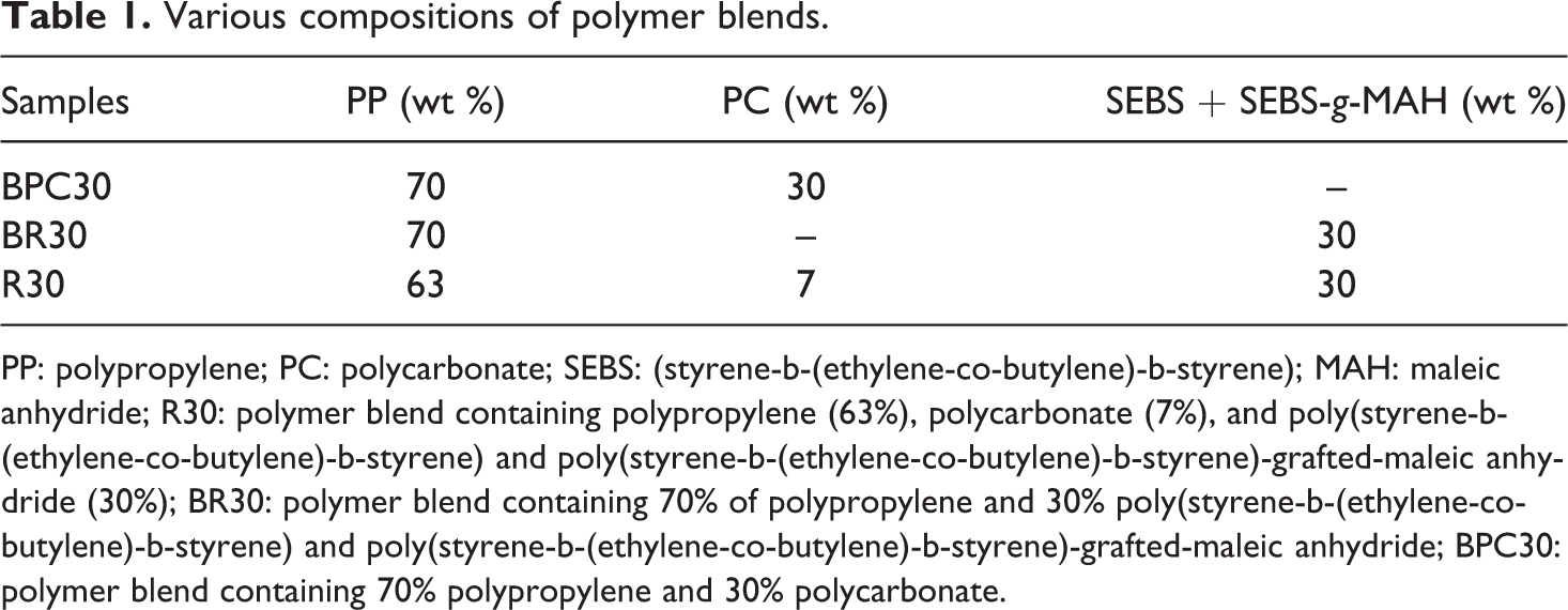
PP: polypropylene; PC: polycarbonate; SEBS: (styrene-b-(ethylene-co-butylene)-b-styrene); MAH: maleic anhydride; R30: polymer blend containing polypropylene (63%), polycarbonate (7%), and poly(styrene-b-(ethylene-co-butylene)-b-styrene) and poly(styrene-b-(ethylene-co-butylene)-b-styrene)-grafted-maleic anhydride (30%); BR30: polymer blend containing 70% of polypropylene and 30% poly(styrene-b-(ethylene-co-butylene)-b-styrene) and poly(styrene-b-(ethylene-co-butylene)-b-styrene)-grafted-maleic anhydride; BPC30: polymer blend containing 70% polypropylene and 30% polycarbonate.
Microscopy and toughening mechanism investigation
The phase morphologies of the PP blends were investigated by SEM (AIS-2100 SEM, SERON Co., Minooka, Illinois, USA). SEM samples were prepared by cryofracture under liquid nitrogen. First the specimens were notched and placed in liquid nitrogen and then fractured using a Zwick pendulum-type tester. The samples containing SEBS were etched by cyclohexane for 24 h to remove SEBS and SEBS-g-MAH minor phases. Then, the etched samples were gold sputtered to make the samples conductive.
The fracture surfaces of the tensile specimens broken in the tensile tests were also investigated by SEM. Tensile tests were performed at room temperature. Then, the fractured surfaces of the pure PP and PP blends were gold sputtered to make the samples conductive.
In the TOM investigation, the necking regions in tensile tests were polished into thin sections so that the samples became transparent. These thin sections were observed using an Olympus DP12 optical microscope (Olympus Co., Germany). The AFM investigations were also performed on these thin sections using an Ambios microscope (Ambios Technology Inc., USA).
Mechanical evaluation
The dried pelletized blends were molded to form bending and impact specimens using an ENGEL ES 150 injection molding machine (Engel Co., Austria). The barrel temperature profile was 180 (hopper) to 240°C (nozzle) and the mold temperature was maintained at 40°C. Tensile stress–strain data were obtained using a Galdabini testing machine (Galdabini Co., Italy) with a crosshead speed of 50 mm/min according to the ASTM D-638 standards. Izod impact strength was measured for notched specimens according to ASTM D-256 using a Ceast Resil Impactor tester (ITW Co., Italy).
Thermal evaluation
The thermal analysis was carried out using a 200F3Maia differential scanning calorimeter (DSC, Germany). Specimens of 5–10 mg in weight were taken and subjected to heating–cooling cycles between 25 and 250°C, with a heating rate of 10°C/min in a nitrogen atmosphere. Indium and tin were used for the temperature and heat flow calibration, and all scans were carried out under high-purity nitrogen gas with the flux of 80 mL/min. Air was used as a reference material.
X-ray characterization
Wide-angle X-ray diffraction (WAXD) experiments were performed at room temperature using an Inel Equinox 3000 powder diffractometer (France) with a sealed X-ray source (Copper) in the standard vertical θ–2θ geometry (40 kV and 50 mA). A germanium incident beam monochromator was used to produce Kα1 free radiation. The wavelength of the incident X-ray was 1.54 Å. Data were collected from 5 to 40° (2θ).
Results and discussion
Morphology
SEM micrographs of the samples according to Table 1 are shown in Figure 1. In the BPC30 sample, PC particles were dispersed and some particles of PC were rod-like particles. In the BR30 sample, SEBS particles were dispersed. In the R30 sample, core–shell morphology (PC particles as a core and the SEBS phase as a shell) could be seen. Figure 2 shows that AFM phase images in tapping mode of R30 and core–shell particles are clearly observed. In AFM phase images, the rigid phase with a higher modulus appears brighter and the soft phase appears darker. The PC component is more rigid than the other components and the SEBS component is softer than the other components. Consequently, the domains of brighter contrast are assigned to the PC component and the domains of darker contrast are assigned to the SEBS component, so in Figure 2 the bright area that is surrounded with the dark area is related to the core–shell particles.
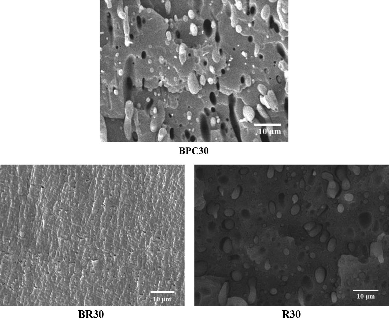
SEM micrographs of PP blends. SEM: scanning electron microscopy; PP: polypropylene.
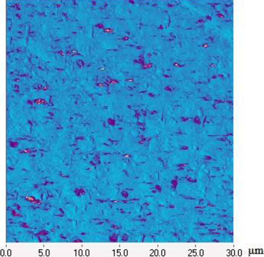
AFM phase images of R30. AFM: atomic force microscope; R30: polymer blend containing polypropylene (63%), polycarbonate (7%), and poly(styrene-b-(ethylene-co-butylene)-b-styrene) and poly(styrene-b-(ethylene-co-butylene)-b-styrene)-grafted-maleic anhydride (30%).
Crystallinity of PP
The DSC thermographs of the neat PP and PP blends are shown in Figure 3. The degree of crystallinity (Xc) was determined from DSC measurements. The Xc can be evaluated from the heat evolved during crystallization (ΔHc) using the following relation:
DSC thermogram of neat PP and blends. (a) the melting curve and (b) the cooling curve. DSC: differential scanning calorimeter; PP: polypropylene.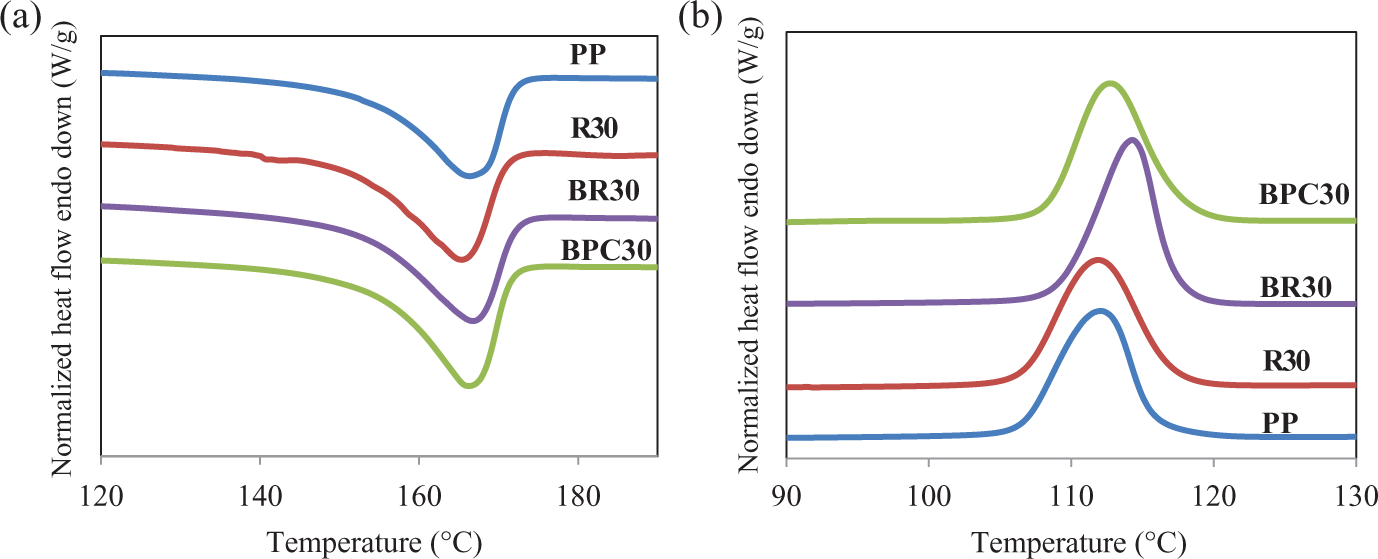

Summary of thermal properties of neat PP and PP blends (sample standard deviations in parentheses).
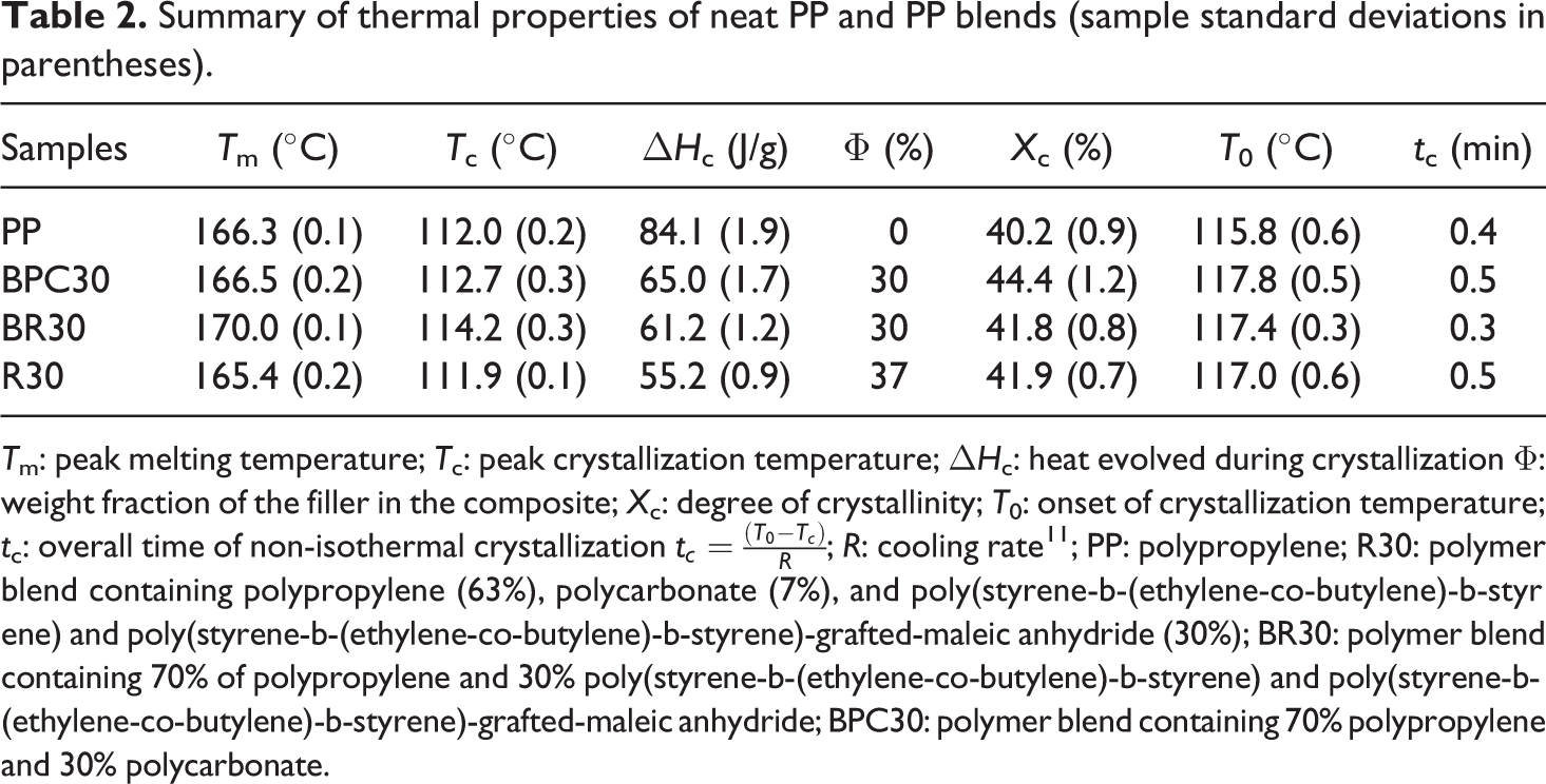
Tm: peak melting temperature; Tc: peak crystallization temperature; ΔHc: heat evolved during crystallization Φ: weight fraction of the filler in the composite; Xc: degree of crystallinity; T0: onset of crystallization temperature; tc: overall time of non-isothermal crystallization
In BPC30 binary polymer blends, the crystallization of PP was affected by the presence of PC. In BPC30, the solidification of PC particles dispersed within the PP melt often results in heterogeneous nucleation, 9,12 which increases the peak temperature (Tc) of the crystallization exotherm of the PP. In BR30 binary polymer blends, the crystallization of PP was affected by the presence of SEBS particles that acted as a nucleation agent for PP, which increased the Tc of the crystallization exotherm of the PP. 9,13 –15 SEBS was more effective than PC as a nucleating agent. The Xc for the various samples are shown in Table 2. In BPC30, BR30, and R30 samples, a slight increase in Xc was observed.
Figure 4 shows the WAXD pattern of pure PP, R30, and BR30. Except for the strong crystallite peaks observed for α-phase crystals in BR30, a weak peak at 2θ = 16.0° that corresponds to the (300) crystal plane of β-phase crystals is observed. Therefore, this confirms that β-phase was formed due to the presence of SEBS in the PP matrix, but the absence of β-phase in R30 indicates that the β-phase was not formed due to the presence of core–shell particles in the PP matrix. Other studies also showed the formation of β-form PP in the PP/SEBS blends. 10,16
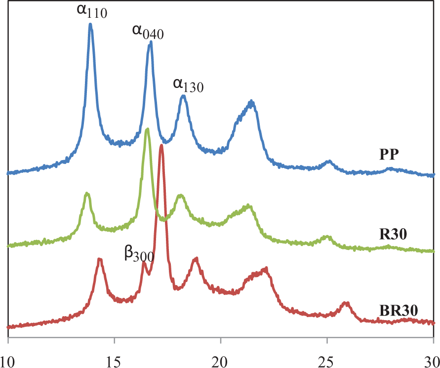
X-ray diffraction patterns of pure PP, R30, and BR30. PP: polypropylene; R30: polymer blend containing polypropylene (63%), polycarbonate (7%), and poly(styrene-b-(ethylene-co-butylene)-b-styrene) and poly(styrene-b-(ethylene-co-butylene)-b-styrene)-grafted-maleic anhydride (30%); BR30: polymer blend containing 70% of polypropylene and 30% poly(styrene-b-(ethylene-co-butylene)-b-styrene) and poly(styrene-b-(ethylene-co-butylene)-b-styrene)-grafted-maleic anhydride.
Mechanical testing
The data from tensile and notched Izod impact testing, performed at room temperature, are shown in Table 3. As a reference, the mechanical property data measured for the blends are compared to those measured for the PP matrix. All the blends exhibited improvements in Izod impact strength compared to the unmodified PP matrix. A slight increase in the impact strength was observed in BPC30 due to addition of PC particles. This is while the fracture behavior of BR30 and R30 completely changed and exceptionally high impact strength was observed. It was observed that PP, BR30, and R30 specimens did undergo necking and yielding during their stretching in the tensile test, but in the BPC30 blend, the necking was not observed. The BR30 and R30 blends exhibited inferior low-strain tensile properties (modulus, yield stress) compared to the matrix PP, but superior ultimate tensile properties while the BPC30 sample exhibited higher modulus and inferior ultimate tensile properties than the PP sample.
Mechanical properties of PP blends and the PP matrix (sample standard deviations in parentheses).
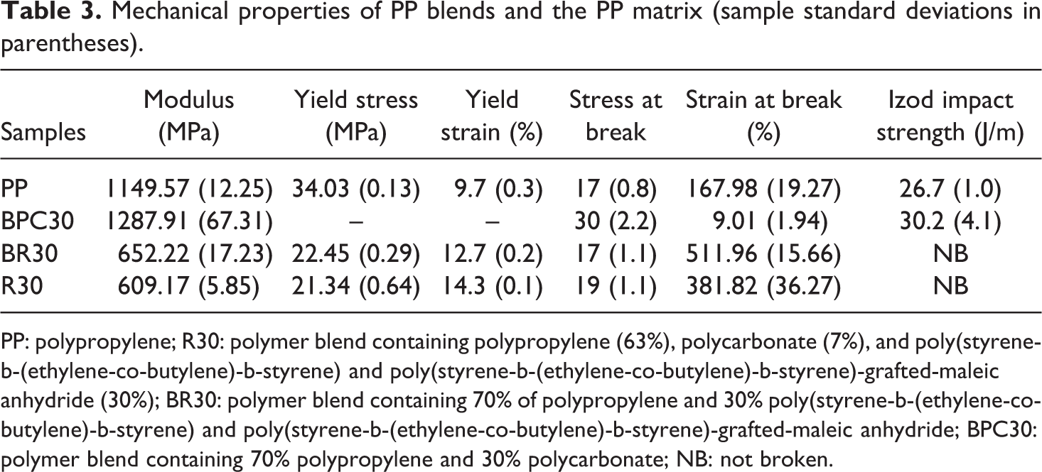
PP: polypropylene; R30: polymer blend containing polypropylene (63%), polycarbonate (7%), and poly(styrene-b-(ethylene-co-butylene)-b-styrene) and poly(styrene-b-(ethylene-co-butylene)-b-styrene)-grafted-maleic anhydride (30%); BR30: polymer blend containing 70% of polypropylene and 30% poly(styrene-b-(ethylene-co-butylene)-b-styrene) and poly(styrene-b-(ethylene-co-butylene)-b-styrene)-grafted-maleic anhydride; BPC30: polymer blend containing 70% polypropylene and 30% polycarbonate; NB: not broken.
Following Corté and Leibler’s theory,
7
the brittle–ductile transition temperature, TBD, of these toughened blends can be calculated by
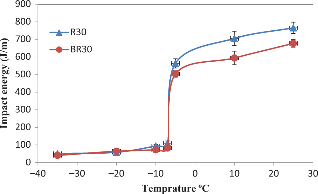
Impact energies of BR30 and R30 blends versus temperature. R30: polymer blend containing polypropylene (63%), polycarbonate (7%), and poly(styrene-b-(ethylene-co-butylene)-b-styrene) and poly(styrene-b-(ethylene-co-butylene)-b-styrene)-grafted-maleic anhydride (30%); BR30: polymer blend containing 70% of polypropylene and 30% poly(styrene-b-(ethylene-co-butylene)-b-styrene) and poly(styrene-b-(ethylene-co-butylene)-b-styrene)-grafted-maleic anhydride.
The modulus of the R30 ternary blend, outlined in Table 3, is related to the phase morphology of the blend. Rösch
18
outlined a scheme to apply the Kerner equation to complex multiphase polymer systems. The Kerner model assumes perfect adhesion between randomly dispersed inclusions of spherical geometry and the matrix, and the shear modulus of a composite is given by:
Young’s modulus E is obtained from the shear modulus, using:

The data used in the equation were sourced from our experimental measurements (Table 2) and manufacturer’s data. The respective densities and Young’s moduli of the PP, SEBS, and PC were 0.9, 0.91, and 1.2 g/cm3 and 1149.57, 100, and 2350 MPa; and the μ of the PP and the SEBS were 0.39 and 0.49, respectively. To calculate the modulus of the R30 blend (with two dispersed phases); first the shear modulus of a PP matrix with a dispersion of SEBS particles was calculated. This calculated value was then used as the matrix modulus in a subsequent calculation of the shear modulus of the R30 blend with a dispersion of PC particles, giving a value of Young’s modulus almost equal to 725 MPa for this blend. To calculate the modulus of the R30 blend with core–shell dispersed phases; first, the modulus of the isolated dispersed particles was calculated with SEBS as the matrix and PC as the dispersed phase. This value was then used as the dispersed phase modulus in a subsequent calculation with PP as the matrix, giving a value of Young’s modulus almost equal to 660 MPa for this blend. Comparing these values with the value of Young’s modulus almost equal to 609.17 ± 5.85 MPa obtained from experimental measurement for the R30 blend confirmed that core–shell morphology (PC particles as a core and the SEBS phase as a shell) and individual SEBS particles formed in the R30 blend.
Deformation mechanism investigation
The fracture surface morphology offers a direct knowledge concerning the structures that are formed upon specimen failure. In this way, one can obtain valuable information on the nature of failure and phase behavior as well as the manner the crack propagates leading to the specimen fracture. Hence, through detailed analysis of the fracture surface morphology, one may collect complementary information on the micromechanical properties of the system.
SEM micrographs of the tensile fracture surfaces of neat PP, BPC30, BR30, and R30 in tensile tests are shown in Figure 6. PP showed a relatively smooth fracture surface. PC particles could be clearly seen on the fracture surface of the blend in BPC30 (Figure 6 (BPC30)) and appear, in many cases, to be clearly debonded from the matrix. In the R30 and BR30, the fracture surfaces changed and substantial matrix ductile tearing confirmed the high energy dissipated during fracture (Figure 6 (R30 and BR30)). Moreover, on the fracture surface of sample R30 (Figure 6 (R30)), PC particles and cavities could be seen. In the fracture surface of BR30, a rough cauliflower-like morphology could be seen (Figure 6 (BR30)). This morphology indicated that there was a significant contribution of irreversible plastic deformation confirming the high energy dissipated during tensile fracture.
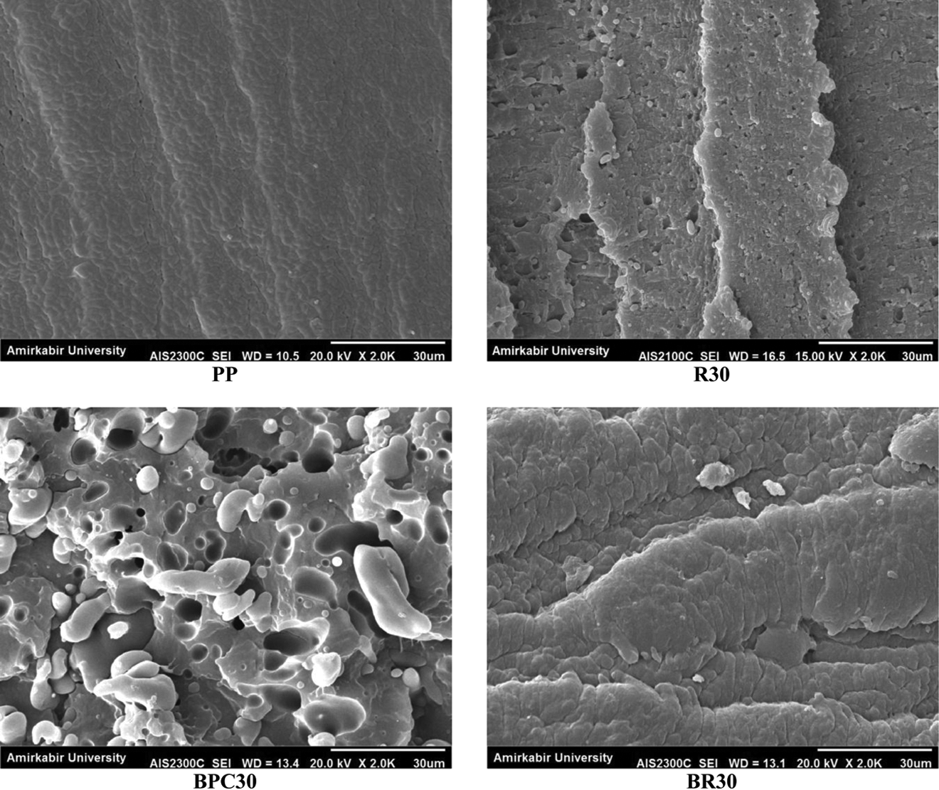
SEM micrographs of tensile-fractured surface of PP and PP blends. SEM: scanning electron microscopy; PP: polypropylene.
For a better understanding of the deformation mechanism, the deformation structures in a tensile bar along the necking region beginning from the undeformed area were investigated via TOM and AFM.
A tensile bar deformed in a tensile test is schematically sketched in Figure 7. The damage zones close to the necking region were polished into thin sections so that the samples became transparent. These thin sections were observed using TOM and AFM.
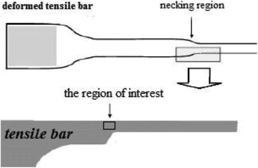
Scheme showing the sample preparation for TOM and AFM studies of deformation structures using tensile bar deformed in a tensile specimen. TOM: transmission optical microscopy; AFM: atomic force microscope.
TOM micrographs and AFM phase images in tapping mode of the necking region of neat PP and the blends are shown in Figures 8 and 9. As illustrated in Figure 8 (PP), crazing occurred in PP and no sign of shear yielding was observed. As shown in Figure 8 (BR30), the optical micrographs of the BR30 sample clearly indicate that shear bands were formed. Crazing also occurred in the BR30 sample, but the dominant deformation mechanism in BR30 under static loading conditions (at low-strain rates) was shear yielding and the polymer molecules tended to align in the direction of 45° to the direction of static loading. Similar to BR30, shear bands were seen in the optical micrographs of the R30 sample (Figure 8 (R30)). As illustrated in Figure 8 (R30), in R30 shear yielding and crazing occurred. Figure 9 (R30) confirm that multiple cavitation formed around PC particles in a rubbery shell. As already mentioned, in AFM phase images, a rigid phase with higher modulus appears brighter and the soft phase appears darker, so in Figure 9 (R30 (b)), the bright area was related to the PC phase and the dark area was related to the SEBS phase that surrounds the PC phase and the darker area in the SEBS phase was related to formation of cavities and indicated that multiple cavitation has occurred.
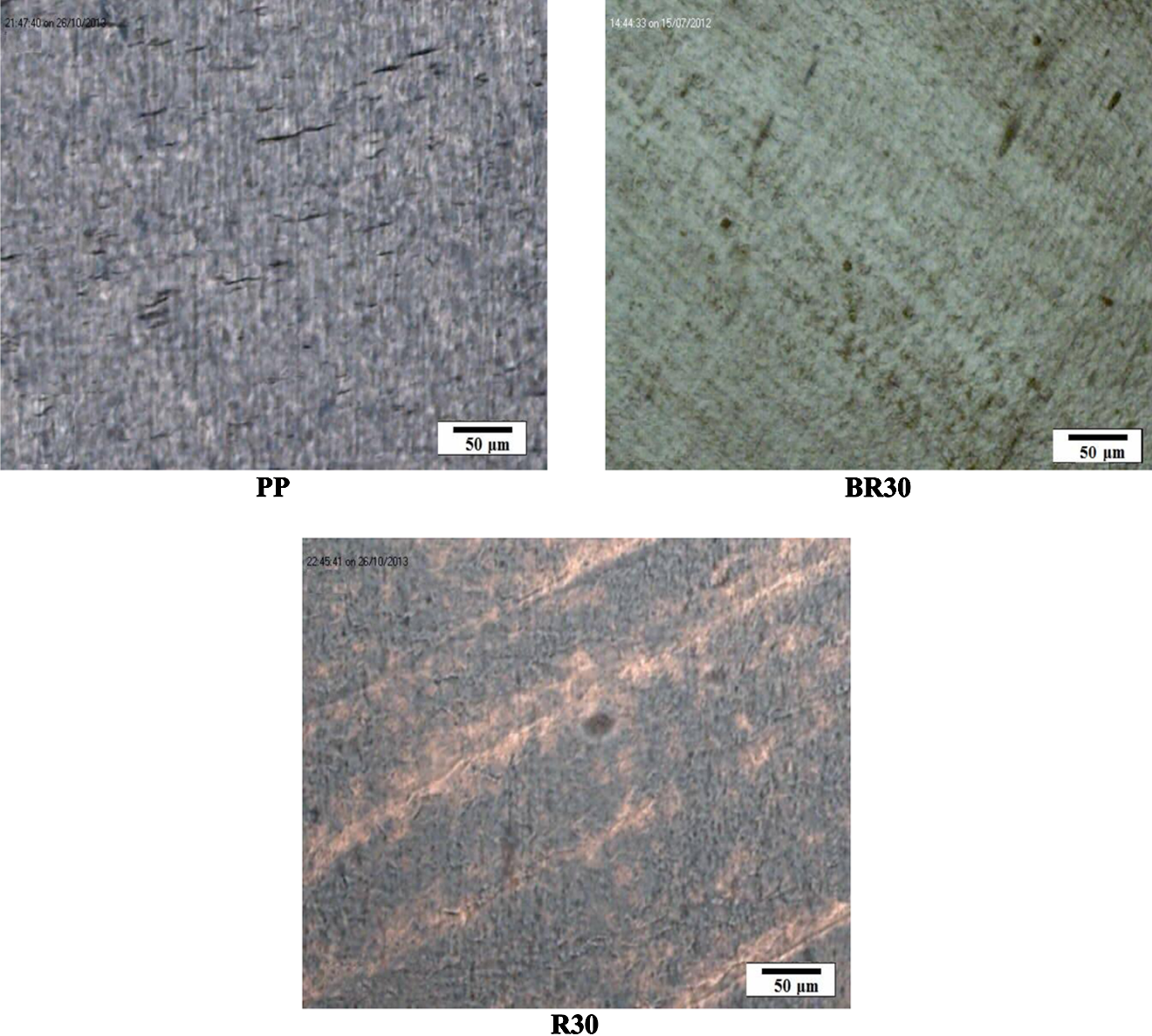
TOM of the necking region of neat PP, BR30, and R30 blends. TOM: transmission optical microscopy; PP: polypropylene; R30: polymer blend containing polypropylene (63%), polycarbonate (7%), and poly(styrene-b-(ethylene-co-butylene)-b-styrene) and poly(styrene-b-(ethylene-co-butylene)-b-styrene)-grafted-maleic anhydride (30%); BR30: polymer blend containing 70% of polypropylene and 30% poly(styrene-b-(ethylene-co-butylene)-b-styrene) and poly(styrene-b-(ethylene-co-butylene)-b-styrene)-grafted-maleic anhydride.
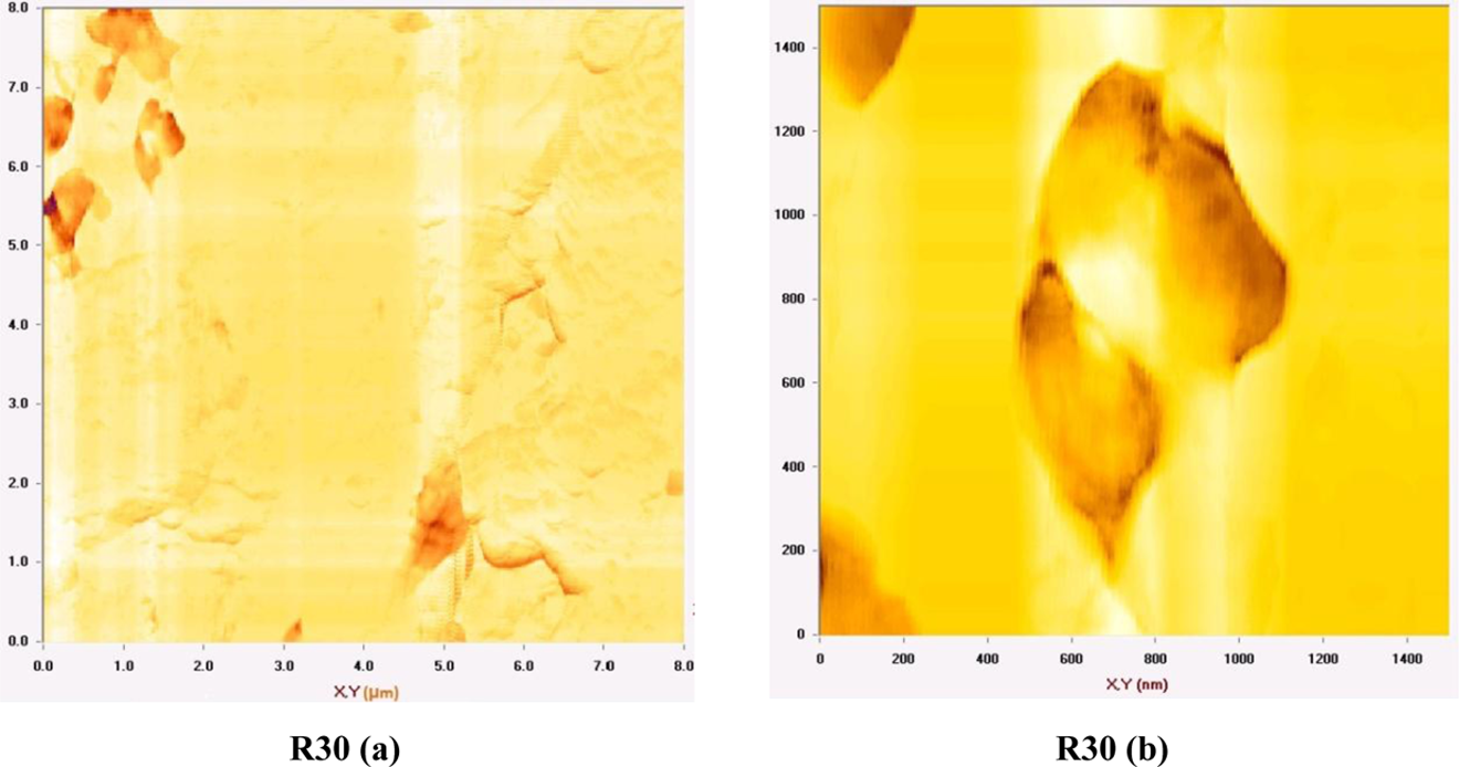
AFM phase images of the necking region of (a) R30 blend and (b) R30 blend at higher magnification. AFM: atomic force microscope; R30: polymer blend containing polypropylene (63%), polycarbonate (7%), and poly(styrene-b-(ethylene-co-butylene)-b-styrene) and poly(styrene-b-(ethylene-co-butylene)-b-styrene)-grafted-maleic anhydride (30%).
Experimental and theoretical studies show the role of rubber in toughening of semicrystalline polymers is mainly related to the cavitation of rubber. The high dilative stresses in front of a growing crack promote the formation of voids in or around rubber particles. Thus, the hydrostatic pressure is relieved near the voids, and stresses are redistributed in a cellular-like material. Cavitated particles act as stress raisers around which the polymer matrix deforms plastically. Yee et al. and Pearson et al. 19 –21 have shown that relief of triaxial tension by rubber cavitation is critical, if the matrix is under plane strain constraint. On the other hand, Sue 22 has shown that the cavitation of rubber particles greatly enhance the possibility for matrix shear yielding to occur without further increasing the chances for undesirable fracture mechanisms, such as crazing and cracking, to take place. Kim et al. have shown that a single or multiple cavitation could occur, depending on the inherent properties and phase structures of modifier particles. 23 Multiple cavitations have also been reported in other ternary blends with core–shell fillers. 8
In both BR30 and R30 samples, cavitation occurred, but in R30, multiple cavitations occurred around PC particles. Formation of microvoids in R30 could clearly be seen in AFM phase images (Figure 9 (R30) (b)), and it seems that the cavitation capability of the core–shell particles is higher than pure rubber particles. Similar observations have also been found in other ternary blends with core–shell fillers. 8
Jang demonstrated that in ethylene propylene diene monomer and in styrene–butadiene rubber-modified PP, the operative fracture mechanisms depend strongly on particle size. Large particles (greater than 0.5 µm) favor crazes, while small particles induce shear banding. 24 As mentioned before crazing and shear yielding occurred in the BR30 sample but the dominant deformation mechanism was shear yielding. Crazing could be attributed to the existence of large particles of SEBS in the PP matrix.
Conclusion
A slight increase in impact strength observed in BPC30 was due to the addition of PC particles. This is while the fracture behavior of BR30 and R30 changed completely and exceptionally high impact strength was observed. The BR30 and R30 blends exhibited inferior low-strain tensile properties than the matrix PP, but superior ultimate tensile properties, while the BPC30 sample exhibited higher modulus and inferior ultimate tensile properties than the matrix PP. According to the model of Corté and Leibler’s, C = 0.18 was obtained for the BR30 and R30 blends and indicated that Corté and Leibler’s theory is unable to describe the effect of core–shell particles.
Crazing occurred in PP and no sign of shear yielding was observed. Rubber particles cavitation, shear yielding, and crazing occurred in the BR30 sample. Similar to BR30, rubber particles cavitation, shear yielding, and crazing occurred in R30.
Footnotes
Declaration of Conflicting Interests
The author(s) declared no potential conflicts of interest with respect to the research, authorship, and/or publication of this article.
Funding
The author(s) received no financial support for the research, authorship, and/or publication of this article.