
Abstract
Pre-consolidated carbon fibre-reinforced polyphenylene sulphide (CF/PPS) laminates were thermoformed into V-shaped parts via designed out of autoclave thermoforming experiments. The different processing conditions tested in the experiment have resulted in final part angles whose differences ranged from 2.087 to 3.431° from the original mould angle. The test results show that processing conditions influenced finished part dimensions as the final sample angles were found to decrease relative to the tooling dimensions, as mould temperature increases. Higher mould temperature conditions produce thinner parts due to the thermal expansion of mould tools. The mould temperature of 170°C, which can produce parts with high degree of crystallinity as well as small size of crystal, has been established as the optimal thermoforming condition for CF/PPS composites.
Introduction
Composites, in general, and carbon fibre (CF)-reinforced plastics, in particular, possess attractive properties 1 –3 such as improved structural performance and lower product weight when compared with their traditional metallic equivalents. For thermoplastic-based composites, improved recyclability 4,5 is another important factor as sustainability is a key requirement for transport systems of the future. One of the major attractions of the CF-reinforced thermoplastic composites (CFRTPs) is the potential rapid processing rates 6 that they offer compared to the existing thermoset systems that require much longer and expensive autoclave processing. In aerospace industry, non-autoclave manufacturing of advanced composites continues to be of interest because of significant cost advantages compared with autoclave-based manufacturing. 7 Thermoforming 8 –12 is a family of process that can be used to process thermoplastic-based composite materials by the combined action of heat and pressure. Within this family, a variety of techniques exist, which could be used to form parts using thermoplastic composite materials. Thermoforming is a three-stage process, involving heating of the raw material blank, coupled with thermal deconsolidation, followed by part forming and reconsolidation in a matched tool, with the final process of step part ejection from the tool, as shown in Figure 1. Matched-die press forming 13 is a widely used thermoforming technique and is used in this work to produce the experimental samples. With thermoforming manufacturing, the thermoplastic materials showing voids or defects can be reconsolidated to eliminate the defects. Complex three-dimensional parts can be shaped or formed from a flat consolidated sheet.
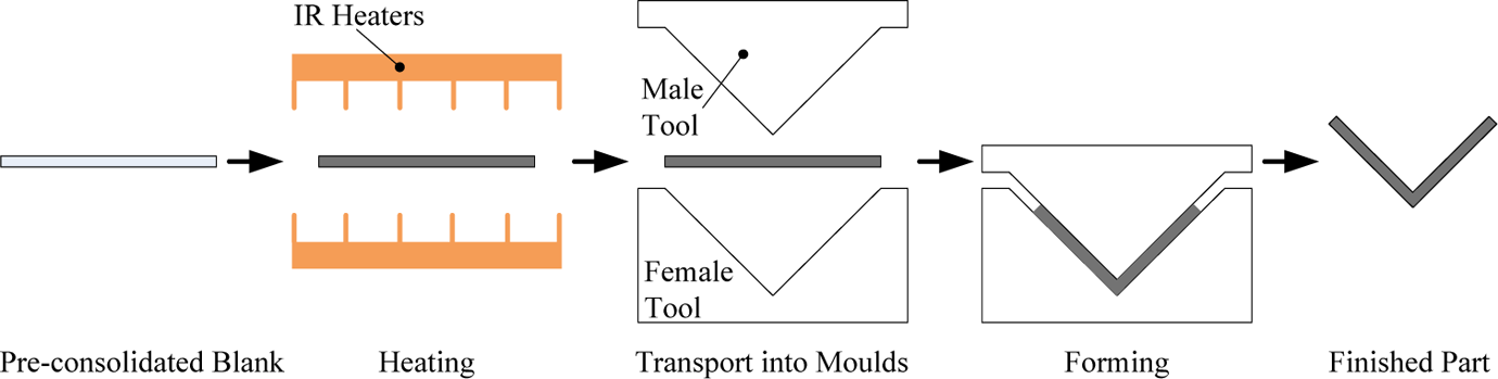
Schematic representation of thermoforming process for thermoplastic composites.
Unlike traditional metallic components, composite structures exhibit more complicated geometric behaviours based on their complex processing history as the assembly of a structure within the material supplements the eventual assembly of parts into a completed product. Process-induced deformations mainly affect the dimensional control of finished components, and this can lead to increased costs as parts become more difficult and therefore more time consuming to fit in place during assembly. For CFRTP parts, which can be prone to geometric variability during thermoforming processing, there is a need for experimental investigation that takes account of these behaviours. The experimental investigation should also evaluate the performance of thermoformed parts under different processing conditions and finally establish the optimal forming condition for the material used in this work. Understanding the deformation behaviour of CFRTPs through experimental investigation can support the mould design in manufacturing as well as tolerance analysis in assembly process. Realistic composite geometries can then be used to inform tolerance allocation during product design and manufacturing planners are also better informed, thereby improving the likelihood of achieving tolerances as parts are formed and products are assembled.
Method
Experiment design
In this work, test samples were manufactured from a commercially available pre-consolidated thermoplastic laminate system consisting of continuous 5-harness satin carbon fibre (T300)-reinforced polyphenylene sulphide (CF/PPS) supplied by TenCate Advanced Composites (Nijverdal, The Netherlands) (material trade name, Cetex® PPS). The laminate consisted of eight plies with 50% fibre volume fraction (V
f) and layup of
Characteristic temperatures of neat CETEX® PPS.
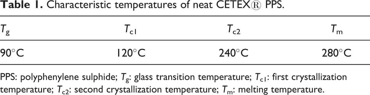
PPS: polyphenylene sulphide; T g: glass transition temperature; T c1: first crystallization temperature; T c2: second crystallization temperature; T m: melting temperature.
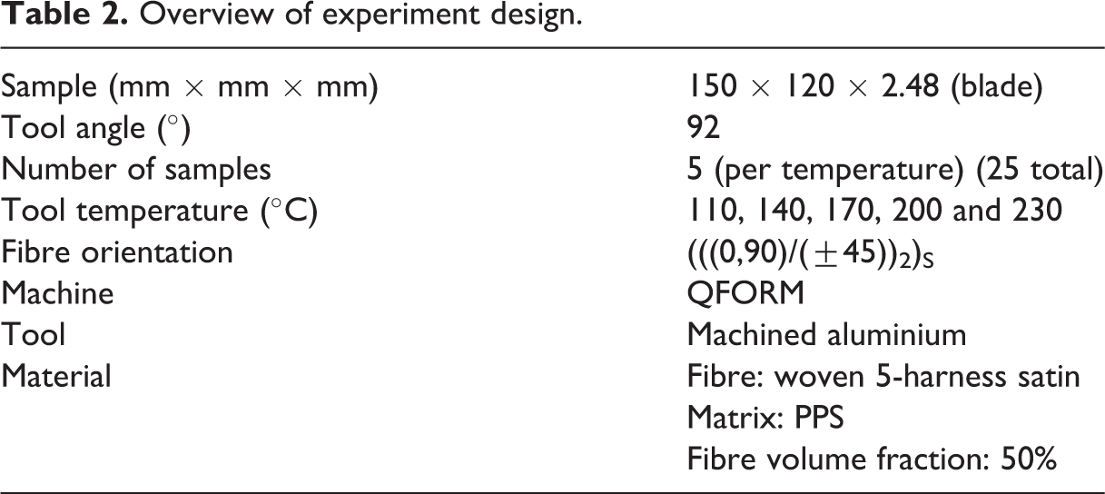
Mould temperatures ranging from 110 to 230°C were investigated to establish optimal forming condition for CF/PPS composite parts. The mould temperature will affect the deformation results of thermoforming composite parts, and it is essential for the quality of final composite part for which the ideal processing window is very narrow. As shown in Table 2, there were five scenarios tested in the experiment, and all the composite parts were thermoformed using QFORM machine with V-shaped moulds. Process-induced deformation is a common phenomenon occurring in the composite part as forming forces and thermal cycles are applied during manufacture. The spring-in angles and thickness of thermoformed V-shaped parts were measured with category of forming mould temperature. This can be used to investigate how the processing conditions will affect the post-forming geometries of CFRTP components. Besides geometry measurement, the thermoformed samples also underwent differential scanning calorimetry (DSC) test to examine the degree of crystallinity (DoC) of PPS in the final composite parts. Other tests were carried out on pure PPS to study the mould temperature effect on the size of crystal (SoC). Equivalent thermal cycles were recreated according to thermoforming conditions of composite parts. Polarized light microscopy was used to inspect the size of the PPS crystals. The design of DoC and SoC tests was to evaluate the mechanical performance of the composite parts formed with different mould temperatures, because the results of DoC and SoC can indicate the mechanical property of these samples. As a range of mould temperatures has been used in the experiment, the relationship between forming mould temperature and finished part performance can be obtained and the optimal processing condition for CF/PPS laminates can be established.
Overview of experiment design.
Apparatus
An in-house developed QFORM thermoforming machine 16 is the main manufacturing equipment used for the experiment. A schematic diagram of this facility is shown in Figure 2. The composite sample is initially retained on the fixture using metal wire hooks connected to transport rail before heating in the oven to reach the processing temperature (for CF/PPS, it is 320°C). The oven use sandwich-type heating panels above and below the sheet. This type of heating is recommended to give even heat distribution across the thickness of the sample. 17 There are totally 12 ceramic infrared heating elements installed at the top and bottom tray of the oven. Each element is measured 245 mm in length and 60 mm in width. The temperature of the oven is controlled using a dual-zone controller (OMEGA CN79000, Omega Engineering Ltd, Connecticut, USA) based on the feedback from the top and bottom heaters separately. During the experiment, the target holding temperature is set as 465°C, 18 according to a heat efficiency study.
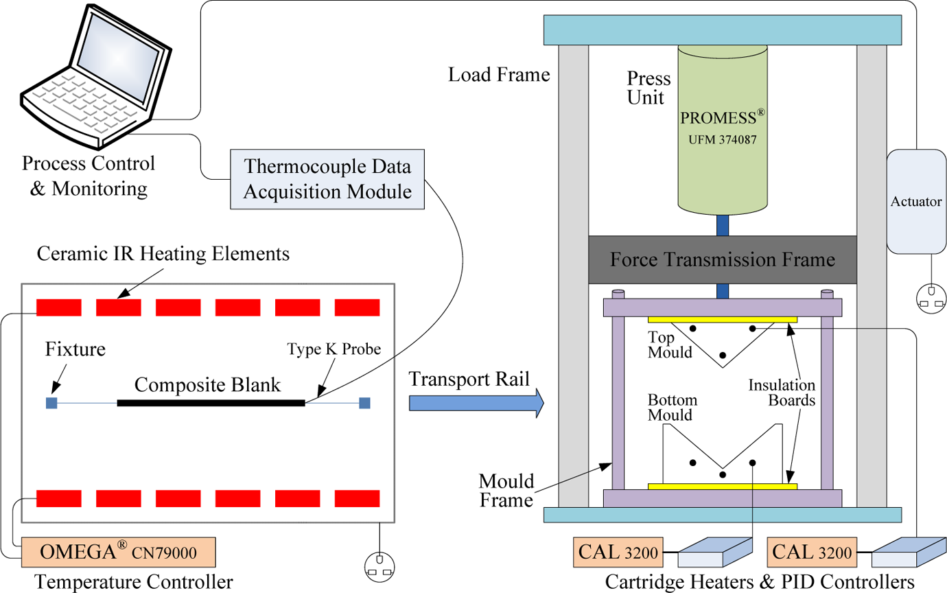
Schematic representation of composite thermoforming machine.
After being heated, the laminate blank will be transferred to the forming station through transport rail. The forming station mainly consists of press unit, mould tools and mould heating system. The 60-kN electromechanical press unit supplied from PROMESS (Berlin, Germany) is suitable for precise and flexible press and positioning tasks. The main parameters of the press unit are specified in Table 3. The pressing, holding and demoulding processes in the forming station are fully programmed through displacement control. The speed of pressing is controlled as well. The top mould started with a speed of 75 mm/s to move downwards to the target position set by the displacement control. The high-speed mould clamping is to prevent excessive temperature drop of the sample due to air cooling. The velocity slowed down to 5 mm/s when the mould is 2 mm away from its objective position as the high-speed mould involved inertia force may damage the composite part. A mould frame is configured to connect the press unit and pass force to forming tools. Therefore, the mould tools are exchangeable as long as they are designed with the assembly feature to the mould frame. Chemical release agent (Alkanes, C7-10-ISO) was painted on the tool surface to facilitate part removal after demoulding. PID controllers (CAL 3200) are used to keep the temperature of the cartridge heaters heated moulds at a set constant value. The cartridge heaters are 150 mm length and 10 mm diameter. The mould temperature is an important processing condition for composite thermoforming and will decisively affect the performance of finished part. Insulation boards are inserted between the heated tools and mould frame to prevent the heat transfer to press unit, which requires operation temperature ranging from −30 to 70°C. During the whole thermoforming process, the temperature of the composite sample is monitored and recorded using an eight-channel thermocouple universal serial bus data acquisition module with sampling interval of 2 s.
Specifications of PROMESS press unit used in thermoforming system.
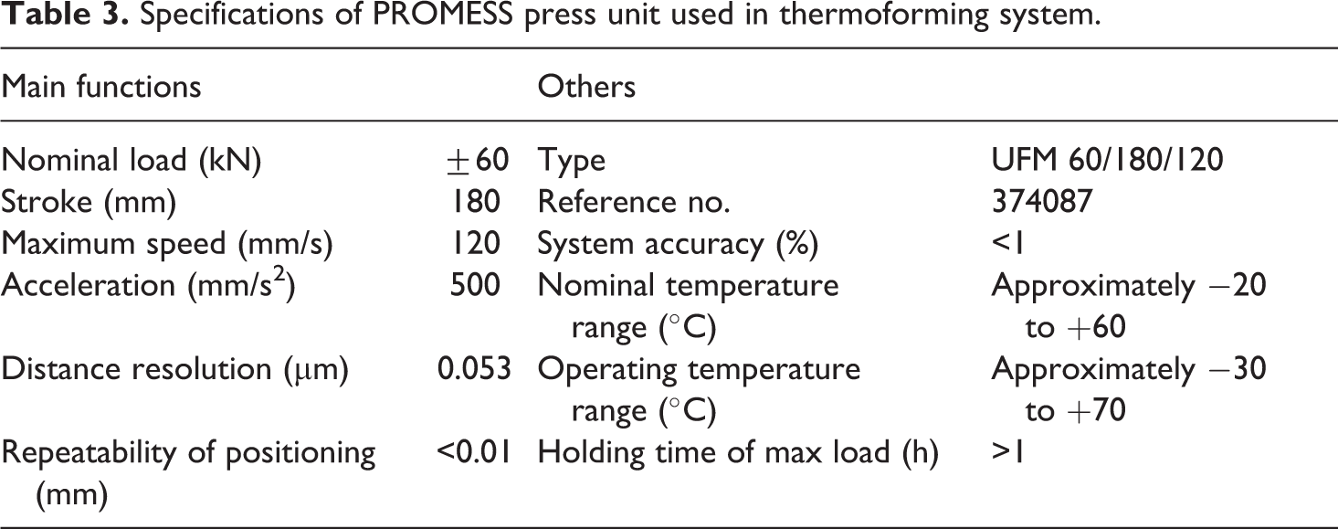
Figure 3 shows the experiment set-up used for thermoforming of V-shaped CF/PPS part. Detailed design geometry of the forming moulds is shown in Figure 4.
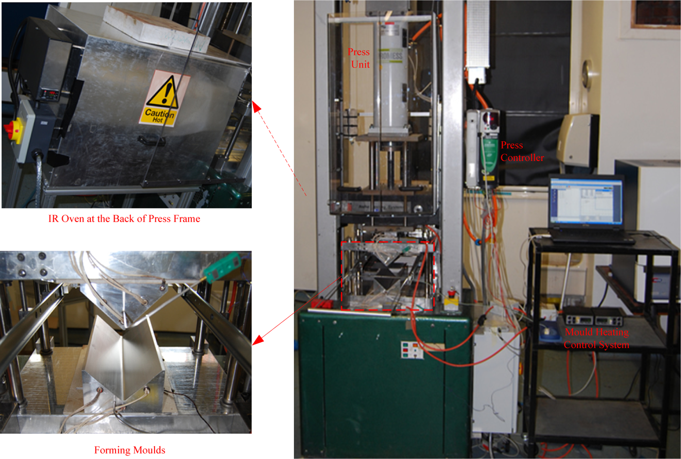
The set-up of thermoforming apparatus in experiment.
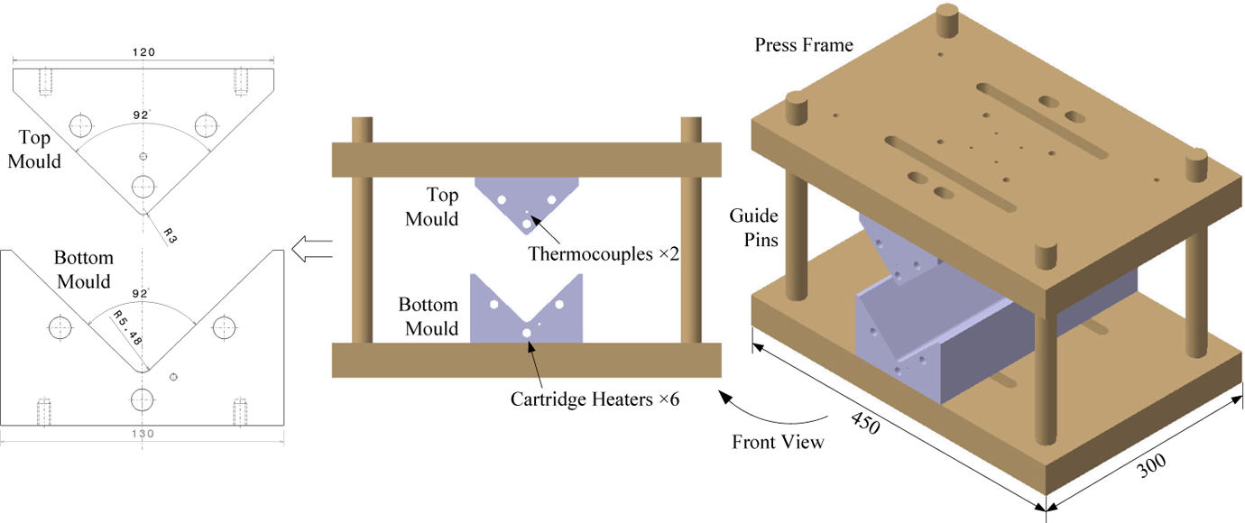
V-shaped mould design for thermoforming experiment.
Thermoforming procedure
For each run of the experiment, the CF/PPS laminate sample was heated in the oven to the forming temperature of 320°C. Once heated, the soft and pliable sample was transferred into the forming station where it was forced into a three-dimensional shape by the mould tools. During the press, the bottom mould was stationary and the top mould was moved downwards through displacement control. The final position of the top mould was set to keep the distance between the moulds the same as the thickness of the original sample (2.48 mm). For different scenarios, the forming moulds were heated and held at a constant temperature, that is, 110, 140, 170, 200 and 230°C, respectively. The part was maintained in the moulds for 180 s after being clamped between the tools. After that, the top mould was moved back to the original position by programmed command and the final part was formed after demoulding, as shown in Figure 5. For each run of the experiment, the parts were immediately removed from the bottom mould after the top mould was lifted up. The parts were then further naturally cooled to ambient temperature outside the mould. The formed part was placed on a laboratory table during the natural cooling stage with the L-shaped edge contacting the tabletop. The thermoformed final parts were used for further inspection such as spring-in angle, thickness measurement and DSC test.
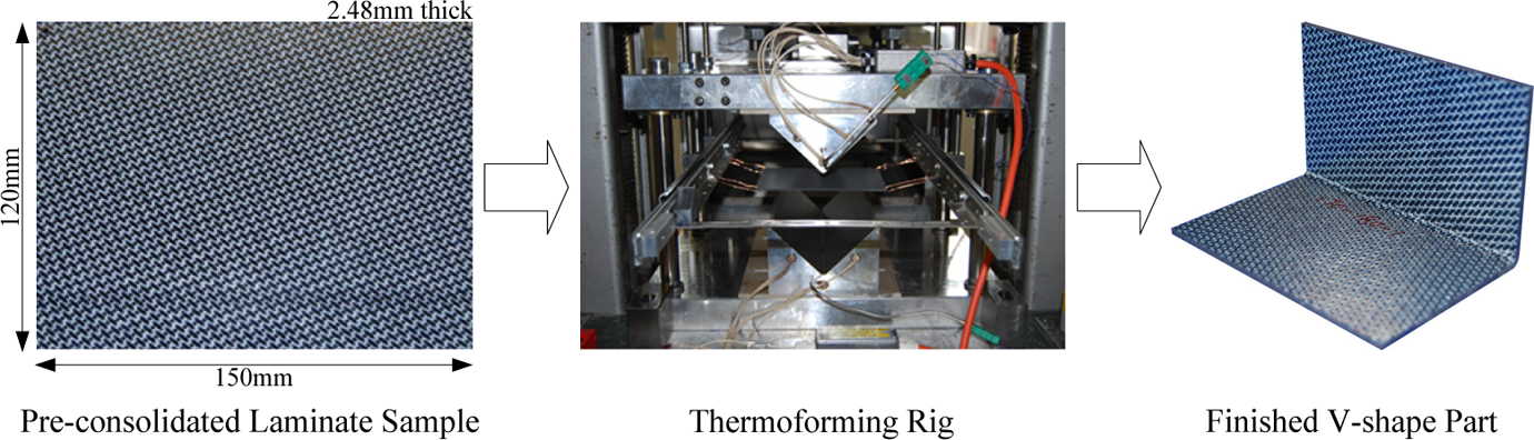
Sample from pre-consolidated laminate to V-shape final part.
The sample temperature during the whole thermoforming process was monitored and recorded using a thermocouple data acquisition module. The temperature profiles of samples formed with different mould conditions are shown in Figure 6. The samples shared similar temperature climb at heating stage in the oven. Then, significant temperature drop was observed when samples were transferred from heating oven to forming station. Their temperature stabilized at constant value when clamped in preheated moulds. After demoulding, the samples naturally cooled with different routes depending on the mould setting. These temperature curves are important basis for recreating equivalent thermal cycles in simulation work.
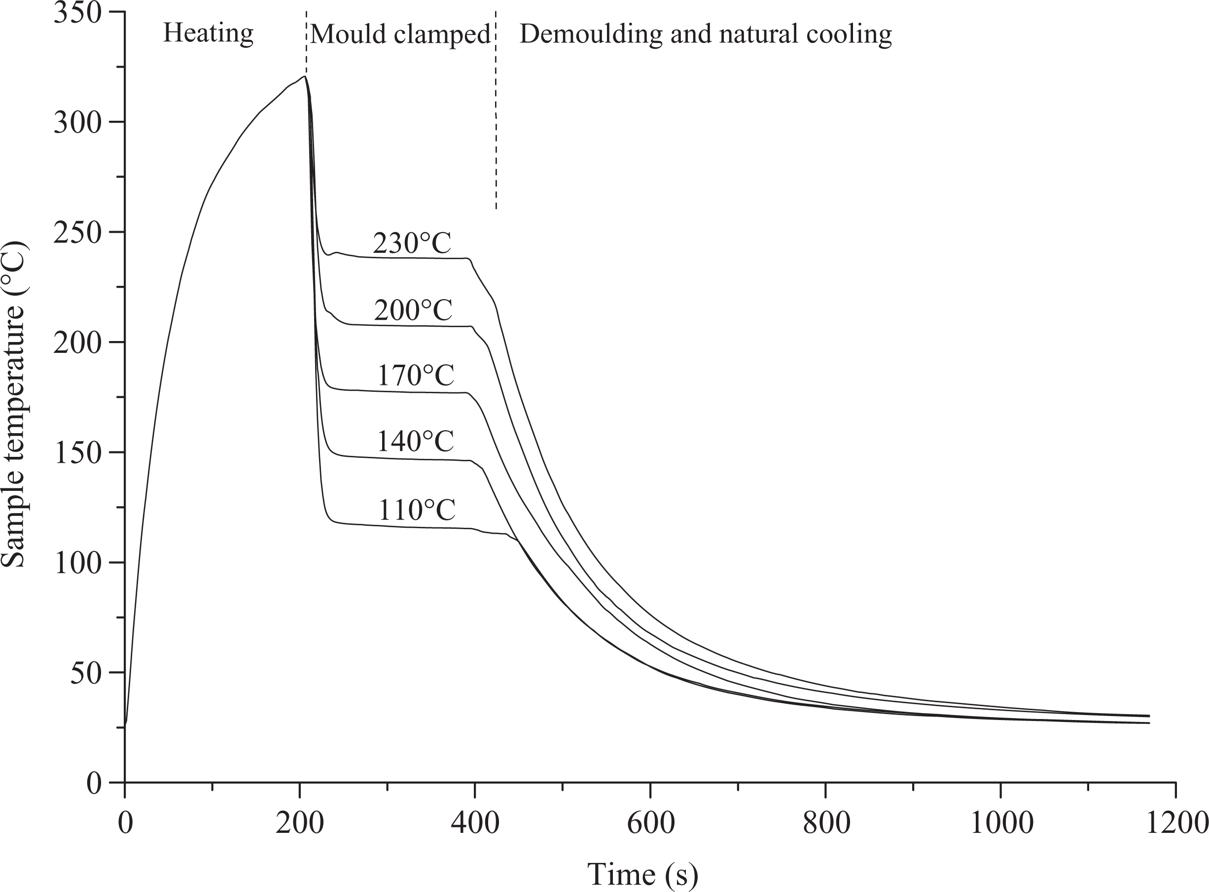
Temperature profile recorded for samples during thermoforming experiment.
Sample inspection
Inspection of the finished part geometries was carried out using a coordinate measuring machine (CMM). CMM is a three-dimensional device for measuring the physical geometrical characteristics of an object. The CMM used in the current work is Brown & Sharpe (Rhode Island, USA) MICROXCEL PFX with 0.5 μm accuracy. This machine can be controlled both manually and by computer. Measurements are defined by a probe attached to the third moving axis (vertical) of this machine, as shown in Figure 7. Both the inner surface and outer surface angles were measured for each sample. For each side of V-shaped parts, the angle was calculated using two planes, which were defined using 20 sample points on each surface. This facilitated the accurate determination of the sample angle, avoiding the possibility of errors arising from single angular measurements, which would have been possible using a Vernier protractor, for example. The thickness of the formed CF/PPS part was measured using micrometer screw gauge. Five positions on each side of the V-shaped part were measured, and the thickness of the part is represented using the average value.
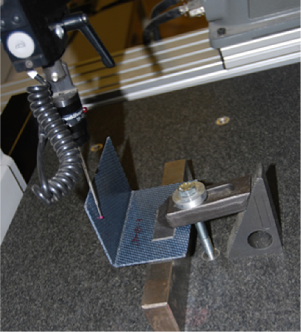
Coordinate measuring machine inspection on finished V-shaped part.
Results
By comparing the finished V-shaped part angle and original mould angle, significant deformation was observed. Figure 8 shows the spring-in angle of a 170°C mould-formed composite part. A 2.525° gap was measured on one side surface between the part and tool when contacting their other side surface together. The mould angle (92°) represents ‘as designed’ part shape and the finished part angle (89.457°) ‘as manufactured’ part form. Therefore, there is inconsistency of ‘as designed’ part geometry and ‘as manufactured’ part form in composite thermoforming.
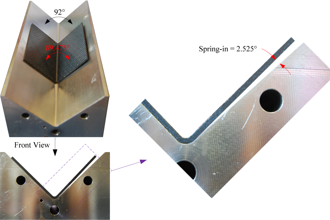
Spring-in deformation of V-shaped composite part.
All the V-shaped composite parts
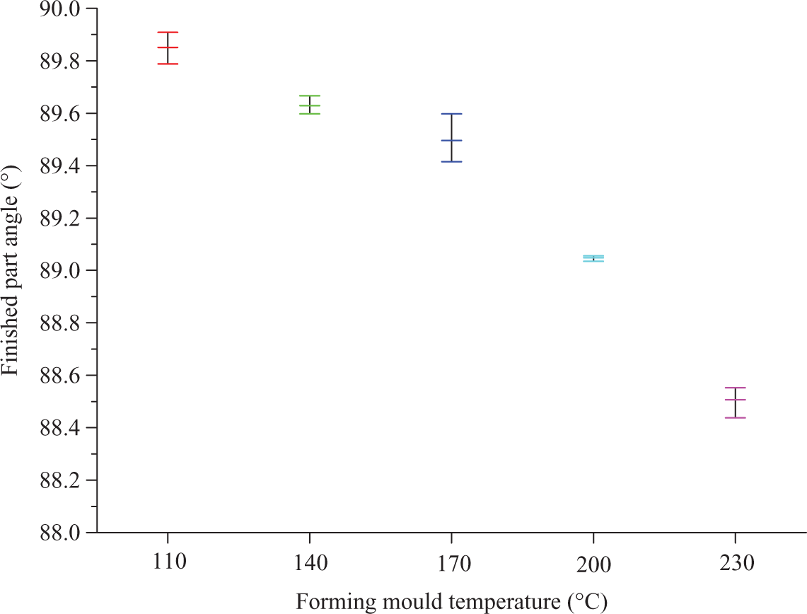
Measured V-shaped part angle for five mould temperatures.
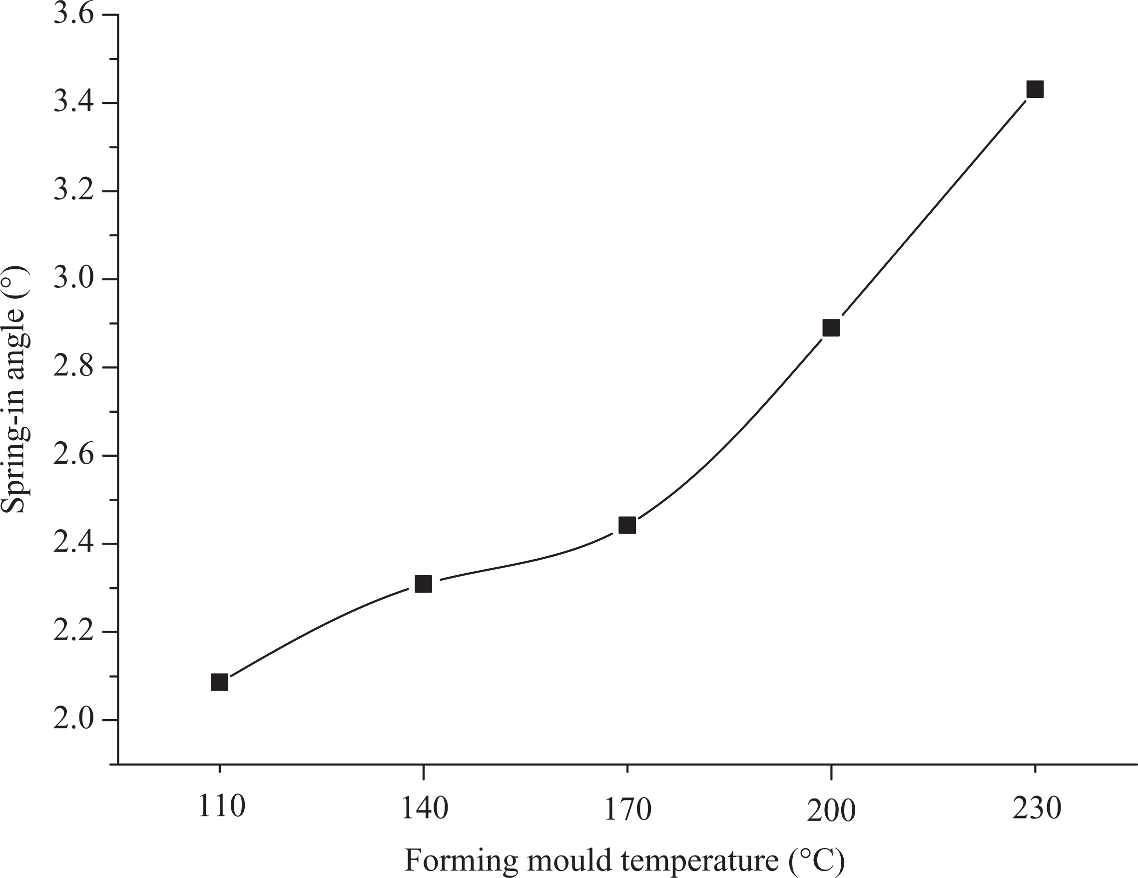
Spring-in angles of thermoformed V-shaped parts.
Micrometer was used to inspect the thickness of the formed CF/PPS parts. The measured thickness results under different forming mould temperatures are shown in Figure 11. The samples formed with 110°C mould have the thickest dimension (2.525 mm average thickness), followed by 140°C (2.503 mm average thickness), 170°C (2.487 mm average thickness), 200°C (2.483 mm average thickness) and 230°C (2.456 mm average thickness) conditions in sequence. The change in sample thickness is mainly due to thermal expansion of the aluminium moulds. The stroke was controlled in the press process through a programmed target position. However, the aluminium moulds were heated to different temperature conditions (from 110 to 230°C), which generated varied geometric expansions of the moulds. Higher mould temperature will cause larger geometric expansion of the moulds, which in turn produce narrower gap between top and bottom moulds. Therefore, the samples formed with 230°C moulds have the thinnest dimension, while the samples formed with 110°C moulds have the thickest dimension.
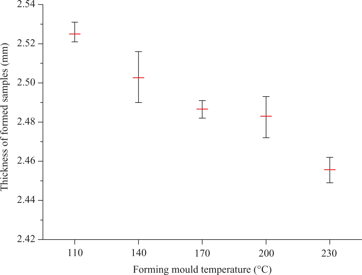
Measured thickness of V-shaped parts under five mould temperatures.
The holding forces applied when the CF/PPS parts were clamped at different mould temperatures were recorded, as shown in Figure 12. The change in holding force is also caused by thermal expansion of mould tools as larger force is required to squeeze the samples when there is a smaller gap between the top and bottom moulds.
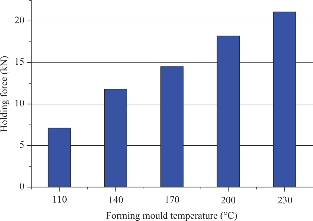
Holding force with different processing conditions.
The angle inspection can demonstrate the mould temperature effect on final composite part deformation. Although desired part shape can be achieved using an appropriate mould temperature, this could sacrifice some of the part quality because the thermal condition is a key factor for finished part mechanical performance. As the crystallization of PPS can indicate the mechanical property of CF/PPS composite, 19,20 samples were tested on differential scanning calorimeter and polarized light microscopy after CMM and micrometer measurements. The tested DSC curves (stacked by Y axis offsets) on samples formed with different mould temperatures are shown in Figure 13. The DSC program set for every sample comprises only a heating procedure from 30 to 330°C at 10°C/min rate.
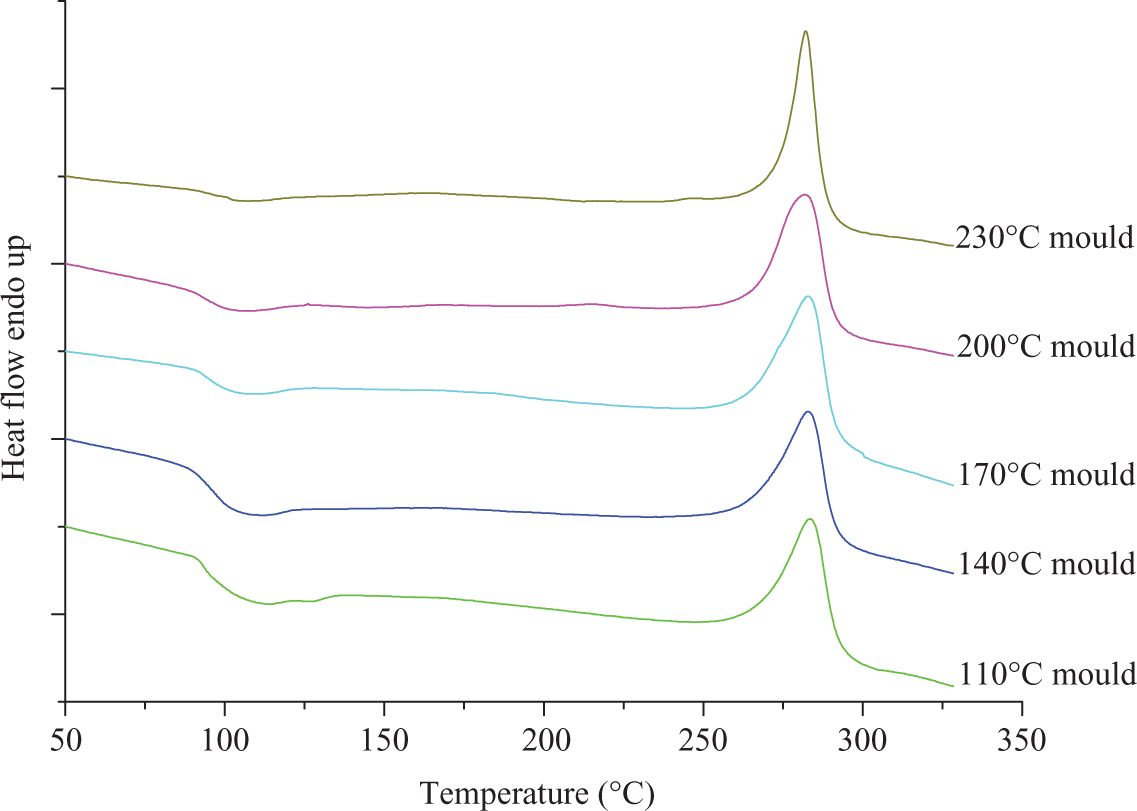
Differential scanning calorimetry results of samples formed with different mould temperatures.
According to these DSC curves, the DoC of PPS in the thermoformed composite parts can be calculated from the following equation
21
:
where
Figure 14 shows the DoC results of thermoformed samples as a function of mould temperature. With the set mould temperature changes from 110 to 230°C, the DoC in the finished composite parts initially increases to reach the maximum value at 170°C mould and then the DoC slightly drops to 230°C mould. Parts formed with 170°C mould have the highest DoC of 34.51%, while parts formed with 110°C mould have the lowest DoC of 25.28%. The nearly 10% DoC gap between the samples could lead to different mechanical behaviour of these composite parts.
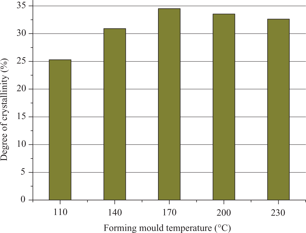
Degree of crystallinity of polyphenylene sulphide due to different processing conditions.
To ensure excellent mechanical behaviour of PPS composites after processing, maximum DoC is usually desired. 19 However, the DoC is not the only criteria to determine the quality of PPS composites. The size of the crystals is also important as larger crystals will cause extensive resin volume shrinkage and can generate microcracks in the composite. Therefore, the optimal performance of PPS composites requires high DoC as well as small SoC. Polarized light microscopy was used to observe the crystal size, and the specimen was prepared using microtome. Trial tests found that it is difficult to cut thin sections (approximately 20–60 μm) from CF/PPS composites due to the brittleness of CF. PPS film was used in this work to inspect the crystal structure. Equivalent thermal cycles were recreated for pure PPS film according to thermoforming conditions of composite parts. The images of PPS crystals under different forming conditions are shown in Figure 15. The dimension of these crystals can be measured on the polarized light microscopy pictures. Figure 16 shows the average size of the crystals with different forming mould temperatures. Samples formed with 170°C tools have the smallest PPS crystal size, which is 7.5 μm. Mould temperatures of 110°Cand 200°C produce similar crystal size, 8.1 and 8.8 μm, respectively. Comparing with the relatively smaller crystal size under low tool temperatures, the samples of 230°C mould have very large PPS crystals which is more than three times the samples by 170°C mould. The results can only illustrate the thermal effect on crystal size of PPS because the stress history of PPS film is different from CF/PPS composites and there is no fibre–matrix interfacial area in pure PPS specimen.
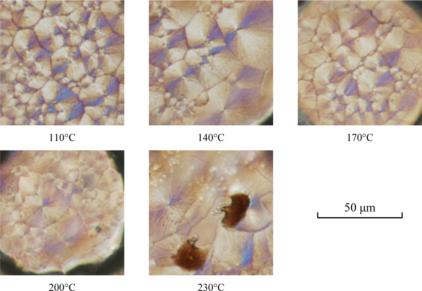
Polyphenylene sulphide crystal structures formed with different processing conditions.
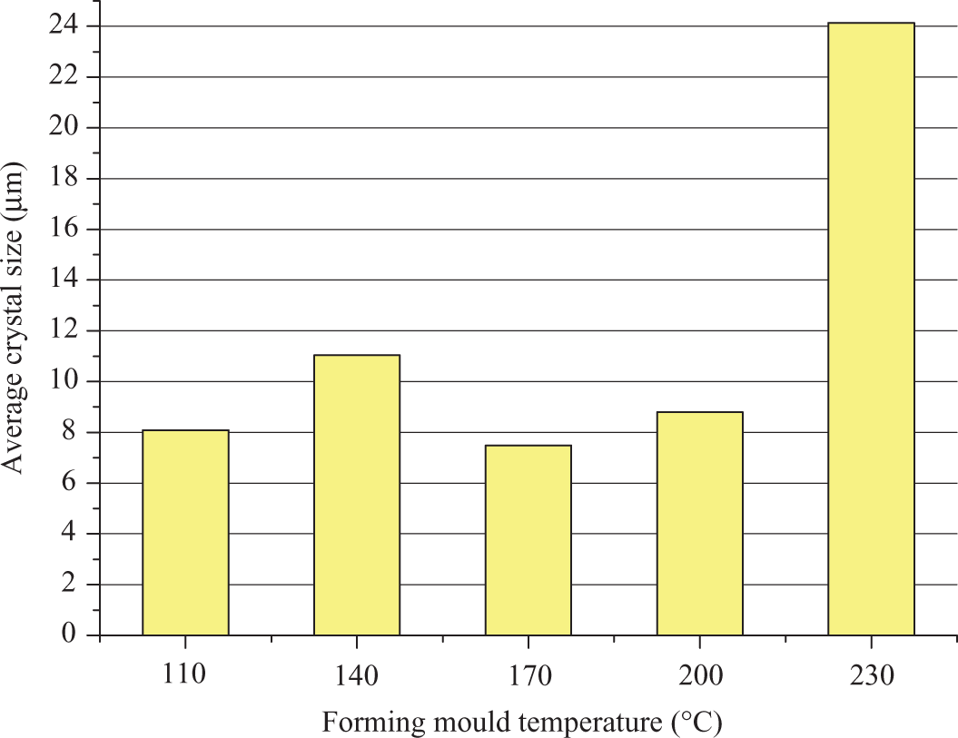
Average size of polyphenylene sulphide crystals formed with different processing conditions.
Discussion
The need for more sustainable transport systems in the future, emphasised more recently by dramatic increases in energy and fuel costs, is driving the development and use of lighter materials, and it is anticipated that composites will play an essential role in the development of next generation transport systems through the remainder of the 21st century. The use of advanced composite materials in modern civil aircraft has increased rapidly because of their net performance advantages in weight and cost over conventional metallic alternatives. Extensive basic research on composite materials over the last three decades has promoted understanding of their basic properties. Nowadays, new composite material systems as well as delivering key in-service performance requirements also should offer more sustainable solutions to their design and manufacturing methods. Out of autoclave thermoforming was applied to produce experimental parts using CF/PPS laminates. The experimental study in this work has shown that for thermoforming a CF/PPS part, the total cycle time was less than 8 min and the total energy consumed is less than 4000 kJ for a sample size of 150 × 120 × 2.48 mm3. Energy efficiency can be exploited using this rapid forming technique as autoclave-based processing could consume 43,200 kJ in 8 min for just reaching a temperature of 149°C.
This work focuses on the angle change of post-forming CFRTP parts relative to mould tools as the previous study 22 has proved that the process-induced composite part deformation is independent of the mould radius. The thermoforming experiments were designed to identify the effects of processing parameters on the finished part angles. The deformation behaviour of a 90°, V-shaped CF/PPS angle was examined using the experimental manufacturing and inspection methods described in previous sections. The V-shaped angular form has been initially used to minimize the range of geometric influences, for example, varied mould angle or complex curvatures, which could affect the shape of the final part. A range of mould temperatures (110, 140, 170, 200 and 230°C) were tested to determine the optimal forming mould temperature for CF/PPS in terms of mechanical performance of finished part. The results arising from thermoforming experiment demonstrate that there is a significant process-induced spring-in deformation ranging from 2.087 to 3.431° from a mould with an angle of 92°. The composites’ anisotropy in shrinkage behaviour, originating from the difference in the thermal expansion of the fibres and the matrix during thermal processing cycle, is the fundamental reason for the part spring-in deformation. After demoulding, the part will deform because of the thermal and crystallization shrinkage during cooling from mould temperature to room temperature. The results of the influence of mould temperature on the deformation were observed that more deformation arises in samples where a higher mould temperature has been used. The samples formed using the 230°C mould temperature will generate the largest shrinkage and spring-in deformation when cooling down to room temperature. This is because the 230°C mould produces a 210°C temperature drop, which leads to largest anisotropic shrinkage strains compared to others conditions. The thickness results of formed parts were measured and the holding forces for these parts during forming were recorded. The changes of thickness and holding force for parts formed with different processing conditions are mainly due to the thermal expansion of aluminium mould tools. When the mould is set at high temperature, for example, 230°C in this thermoforming experiment, the aluminium tool will expand more in size which in turn produces a smaller gap between the matched moulds. The data also illustrate that a larger holding force is used when forming part with a higher mould temperature. This is because the displacement control is applied in the experiment. The samples formed with higher mould temperature will expand more and require a larger press force to reconsolidate the laminates to their original thickness. Based on the experimental investigation of post-forming CFRTP part geometries under different processing conditions, more realistic composite geometries can then be used to inform tolerance allocation during product design and manufacturing planners are also better informed, thereby improving the likelihood of achieving tolerances as parts are formed and products are assembled.
The performance of the finished parts under different mould temperatures was evaluated using crystallization tests, which can indicate the mechanical property of the sample. This is to establish the optimal mould temperature for thermoforming parts from CF/PPS laminate used in the current work. Maximum DoC is usually desired to achieve excellent mechanical performance of CFRTPs, but the SoC is also important as large crystals can generate microcracks in the composites. The tested results show that sample thermoformed with 170°C mould will possess the largest DoC of 34.51% and the smallest average SoC of 7.5 μm. This is mainly due to the fact that the 170°C mould temperature is the balanced thermal condition that affects two cooling stages: the cooling during transfer from forming temperature (320°C) in the oven to forming mould and the cooling to room temperature (20°C) after demoulding. Other mould temperature conditions could produce larger temperature gradient in either first cooling stage or second cooling stage. Large temperature gradient means the part is usually formed with large-sized crystals and low DoC, as there is not enough time for the formation of every crystal. Therefore, the 170°C mould temperature is the optimal processing condition for CF/PPS composites in terms of the finished mechanical performance and should be applied to thermoform CF/PPS parts if the mechanical performance is the priority requirement. With the fixed mould temperature condition of 170°C, two different cooling processes were investigated in this work. The recorded temperature profile of samples cooling outside the mould (natural cooling) and inside the mould is shown in Figure 17. The geometric inspection on the formed parts finds that samples cooling inside the tool have an average angle of 89.483° and an average thickness of 2.502 mm. Compared with the naturally cooled parts have 89.496° average angle and 2.487 mm average thickness, the results illustrate that samples cooling inside and outside tool have similar final part shape, and the post-forming geometries of formed parts are more related to mould temperature. The DSC test on samples cooling inside the tool shows that they have higher DoC of 36.57% compared with the naturally cooled parts, which have DoC of 34.51%. However, part with inside tool cooling takes 135 min to reach room temperature and the forming facility is not available for the next sample during the cooling process, which is more inefficient and time consuming.
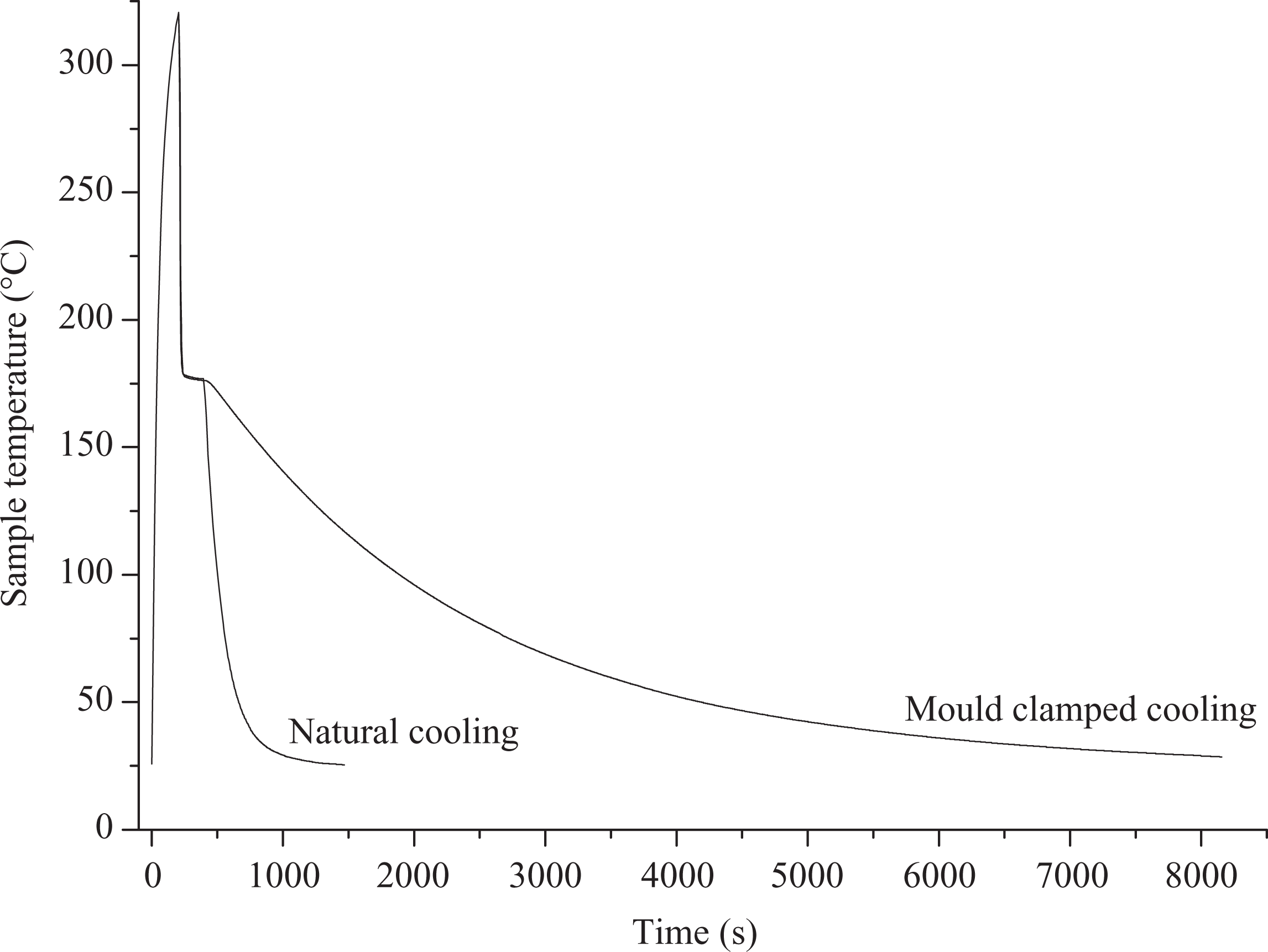
Temperature profile of samples cooling inside and outside tool.
Conclusions
The main objective of this work was to investigate the deformation behaviour of CFRTP part during thermoforming process so that the optimal processing temperature can be established and manufacturing engineers can better understand the relationship between processing conditions and final part geometries. Press thermoforming experiments are implemented to investigate the deformation behaviour of CFRTPs. Sustainability can be achieved through the use of CFRTPs provided with reusability and rapid thermoforming provided with low energy processing. For CF/PPS used in the current work, the experimental investigation finds that, for the different processing conditions tested, there is significant process-induced spring-in deformation ranging from 2.087 to 3.431° for
Footnotes
Funding
The authors would like to thank the Department for Employment and Learning (Northern Ireland) for their financial contribution to the All Island Research Programme and Queen’s University for their support in this project.