
Abstract
When lightweighting studies are examined, thermoplastic matrix composites come to the fore as they have a high specific strength, are recyclable, and can be formed by thermoforming. Some obscurity needs to be overcome for the rapid forming of three-dimensional parts from laminated thermoplastic composites. In this study, deep drawing experiments were carried out to investigate the forming capabilities of continuous glass fiber reinforced polypropylene composite laminates. The parameters of drawing depth, laminate temperature, holding pressure, and punch speed were examined at each three different levels. The effects of these parameters were evaluated on the earing defect and the thickness distribution. It was concluded that the laminate temperature affected both deformations the most. It was determined that all parameters caused a change in flange diameter, but the amount of earing increased with the increase of drawing depth. It was established that inhomogeneous thickness distributions occurred in the part and the highest thickening took place in the curve region.
Introduction
For sectors that require the use of light materials, polymer matrix composites are widely preferred instead of metallic materials. However, thermoplastic composites have come to the fore in terms of reducing environmental impacts. Nowadays, it has been focused on thermoplastic composite laminates especially for the development of cost-effective solutions in the automotive industry. 1 Thermoplastic composite laminates are an alternative material option to sheet metals. It has high strength thanks to its continuous fiber reinforcement and easy forming due to the thermoplastic matrix. 2 In addition, it is possible to be manufactured in sheet form, quickly formed by molding and can be integrated with injection molding etc. operations. 3 Thermoplastic composite laminates are turned into the final product by the thermoforming method in the mold prepared in accordance with the designed shape. In the thermoforming method, after the composite laminate is heated, it is placed in the mold (pre-heated) and formed by applying pressure. In this process, deformations such as thickness change, ear formation, wrinkling, and delamination occur in the sheet material. 4 Researchers and manufacturers are investigating the causes of these defects that affect part quality, whether they are within acceptable limits and conducting research to minimize them. 5 Mao et al. 6 investigated the forming of glass fiber reinforced PP (Polypropylene) composite laminate at different speeds and temperatures by both experimental and finite element analysis. They determined that as the preheating temperature increased, the stress that the specimen can withstand decreased due to the increase in the matrix relaxation behavior, and the damage rate of the specimen increased after 25 mm depth. Mattner et al. 7 investigated the part surface quality in forming glass fiber reinforced PP thermoplastic composite laminate at high speeds. They stated that by using cold molds in the processes, the shortened manufacturing cycle time and energy savings were achieved. They also emphasized that to benefit from viscoelastic flow as much as possible, the forming should be completed without falling below the recrystallization temperature of the thermoplastic, and for this, the deformation rate should be high. Moreover, they determined that forming could be done without damage up to 3 m/s deformation speed. Labanieh et al. 8 studied the defects to be encountered in the pre-forming process of composite parts. They determined that ear formation decreased in parts with short diagonal lengths. They reported that the shear stress and pre-forming force decreased due to the decrease in the contact surface area and tangential friction force in the specimen with short fiber length in the diagonal direction. Therefore, they wrote that weak zones were formed. Khan et al. 9 investigated the effects of punch speed, gripper force, and coefficient of friction on wrinkling and earing deformations. When they compared the corner profiles of the formed part, they determined that unsymmetrical earing occurred due to the different pressing force. Bel et al. 10 studied the three-dimensional forming behavior of different thermoplastic prepregs containing non-woven bi-directional fiber and woven fiber reinforcement. They determined that there was less shear in the woven material. However, they also determined that the top and bottom layers of the nonwoven material shifted relatively. Suresh and Kumar 11 investigated the forming of woven glass fiber reinforced PP composite laminates using different mold and specimen temperatures at different holding forces. They studied the drawing ratio and the logarithmic thickness variation. They found that the flange thickness thickened by 16% at low die temperature and thinned by 22% at high die temperature. They explained that increasing the holding pressure reduced the circumferential yield strength and caused an increase in flange diameter since it increased the radial tensile stress. Lessard et al. 12 investigated thermoforming for three-dimensional part fabrication from 0/90° array carbon fiber reinforced PEEK (Polyether ether ketone) composite laminate. It was determined that the mold temperature and holding pressure parameters had a greater effect on the thickness change and shear strength of the plate compared to the preheating temperature and the plate transfer time from the furnace to the mold. Cabrera et al. 13 performed a feasibility study to prove the formability of self-reinforced PP composite films using a punch. They determined that the all-PP woven laminates did not shear between layers and behaved as a single structure under bending stress. They explained that in the deep drawing process, the composite laminate showed almost isotropic material properties, a substantially equal biaxial strain occurred, and no wrinkling was observed. Lee et al. 14 investigated the deep drawability of hybrid (sandwich structure consisting of metal sheet and carbon fiber reinforced polymer material) composite materials. They examined the effects of different punch speeds and holding pressures on the regional thickness variation of the part and the maximum drawing depth. They stated that the depth of the part increased at low holding forces, the deformations become irregular due to fiber orientation as the punch speed increased, the thickness change was not homogeneous, and separations occurred between the composite and the sheet metal. Benkadour et al. 15 studied the 3D forming of composite laminates prepared by arranging unidirectional carbon fiber reinforced PEEK (poly-ether-ether-ketone) prepregs in opposite orientations by thermoforming method. They stated that they examined the molding parameters in terms of cycle time and that the heat loss in the transfer of the composite material from the furnace to the mold affected the forming. They also reported that a more uniform thickness distribution was achieved under the same conditions when PI (Polyimide) film was used between the holder and the composite plate. Alcock et al. 16 found that the thickness in the 0 and 90-degree directions decreased more than that in the 45-degree regions in their study on the forming of self-reinforced woven polypropylene composites with a hemispherical punch. When manufacturing parts from continuous fiber-reinforced thermoplastic composite laminate, extensive knowledge is required to determine the thermoform forming behavior of the composite in terms of part and mold design for proper process management. To apply thermoplastic composite laminates to vehicle body parts, potential problems should be determined by deep-drawing before thermoforming. The quality of the formed part is related to the correct selection of forming parameters. In this study, the forming of cross-ply laid-up continuous glass fiber reinforced polypropylene composite laminates with a hemispherical punch was investigated. Ear formation and thickness variation, which are important factors for forming quality, were investigated experimentally. An experimental method similar to that of metals was upgraded to evaluate the thickness variation, and its functionality was discussed. It is thought that the information obtained in this study will contribute to future studies and enable them to be more detailed.
Material and method
In this study, polypropylene-based thermoplastic composite laminates containing 60% by weight continuous glass fiber were used. Plates prepared by stacking unidirectional prepregs in a 0/90° structure, and manufactured by compression molding method were preferred. The thick composite laminate consists of 12 layers and is ready for thermoforming. Ready-made composite boards do not contain any adhesive or similar additives. Material characterization was performed, and it was determined that the tensile strength of the composite laminate was 432 MPa, the recrystallization temperature was 124°C, the HDT softening temperature was 159oC, and the melting temperature was 169°C. The water jet cutting method was used to prepare the 90 mm diameter deep drawing specimens. The specimens were cut from 0.5 x 0.5 m2 composite laminates. Section thickness was measured from three random points on each specimen. The initial thickness of the laminate was calculated as 3.06 mm with a variance coefficient of 1.4%. The thickness distribution of the deformed parts was determined with reference to this value and 3.06 mm was marked as 100% in the figures.
The composite laminate was drawn deep into the mold with an inner diameter of 52 mm using a 45 mm diameter spherical punch. The curvature of the mold used is 6 mm. The plates were heated to a certain temperature before being deep-drawn and three different specimen temperatures (124, 159, 169°C) were taken into account. In the experiments, the mold was conditioned to 55°C. During the process, three different holding pressures (0.4, 0.6, 0.8 MPa) were used between the die and the holder. Three different punch speeds (90, 120, 150 mm/min) were selected to determine the effect of forming speed. The forming process was finished at three levels of depth (20, 25, 30 mm).
Control of ear-formation
The hemispherical cup-shaped specimens that emerged after the deep drawing of the composite laminates were visually inspected. The effect of forming parameters on the quality of the part was investigated. Failures such as tearing, cracking, and separation of layers were evaluated. In addition, ear deformation was measured. After forming, final diameter measurements were measured with a digital caliper over the 0/0 or +90/-90 axes and ±45/45 axes, as shown in Figure 1. Here, the gray outer circle represents the full circular diameter of the specimen before the test, and the yellow curve represents the circumference of the specimen flange after the test. The inner-circle in blue indicates the smallest flash diameter of the deep-drawn part. Schematic representation of the ear-formation.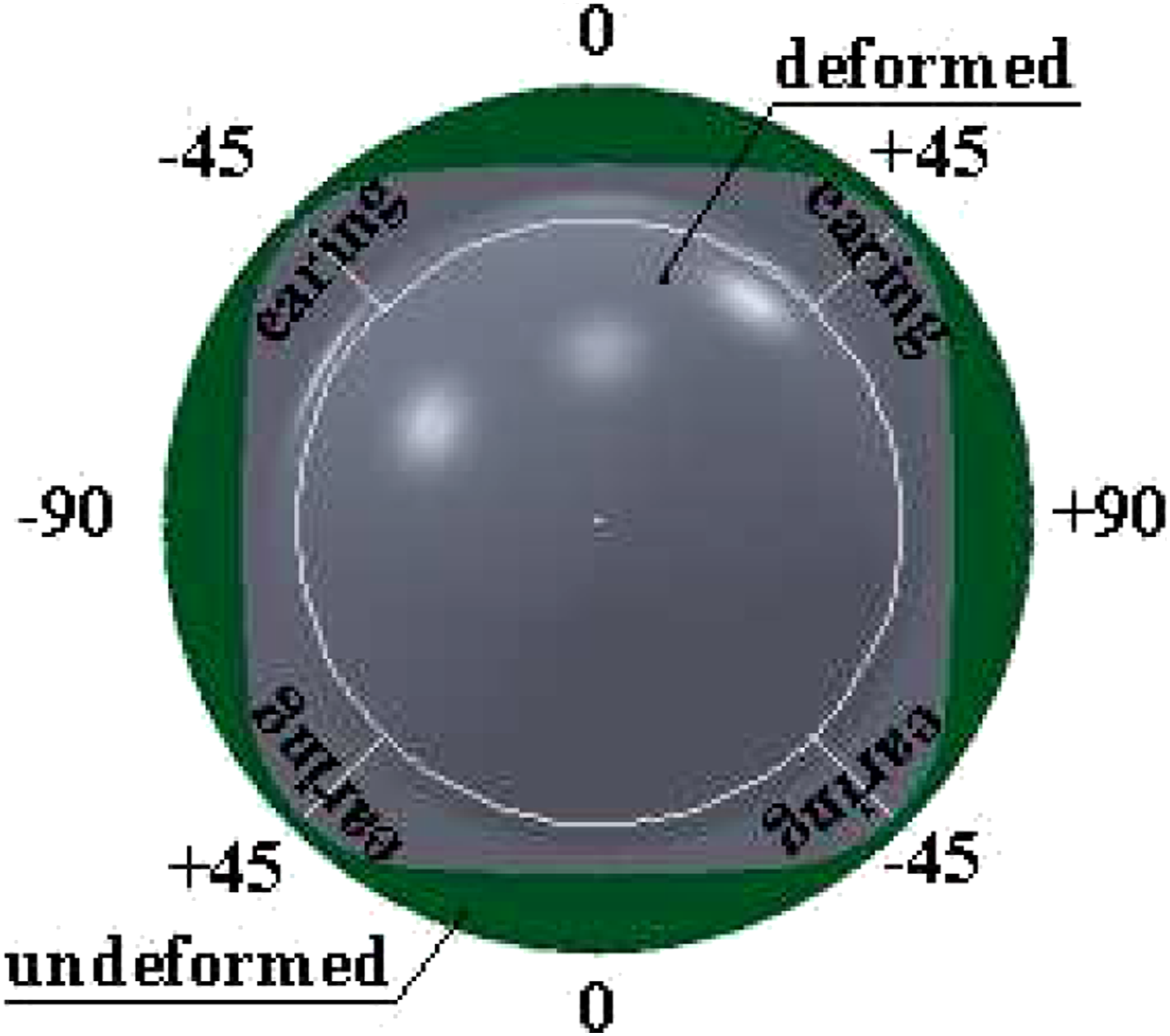
Measuring the thickness distribution
After manufacturing composite parts with curvilinear geometry, thickness differences are measured by a long-arm comparator. In this study, sections were taken from deep-drawn specimens, and the thickness change was measured from certain regions by a precision-armed digital micrometer (sensitivity ±0.01 mm). Since the specimen changes shape symmetrically, thickness measurement was taken from the points seen in Figure 2 (t0, t2, t4, t6, t7). An angle gauge was used to make the measurement points comparable. As shown in Figure 2, measurements were made from the 0/30/60/90° regions and the curvature (t6). Here, d is the flange diameter of the specimen after deep drawing. Schematic representation of the thickness distribution measurement.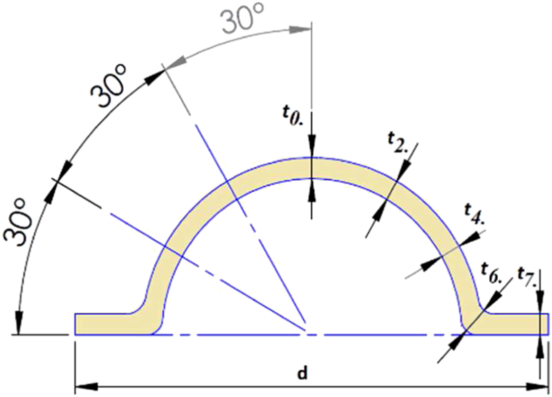
Results and discussion
Effect of forming parameters on ear-formation
The fiber directions of the diagonally arranged prepregs are in the direction of the 0 and 90-degree axes. As seen in Figure 3, there is no fiber orientation between the horizontal and vertical axes. As is known from isotropic materials, the maximum shear occurs in planes of 45°. As in this theory, the shear was effective at all four corners in deep-drawn composite plates. Labanieh et al.
8
also explained that tensile deformation occurred in the 0-degree direction and shear deformation predominated in the 45-degree regions. Therefore, length measurement was performed from the edge and corner directions to determine ear formation in formed specimens. To determine the final diameter values of the specimens, small diameter values were measured from axes 0° - 180° or 90° - 270° and large diameter values from 45° to 225° or 135o to 315o axes (angle change clockwise). The difference between the small radius and the large radius is expressed as the amount of earing. Fiber orientations of cross-ply laid-up prepregs.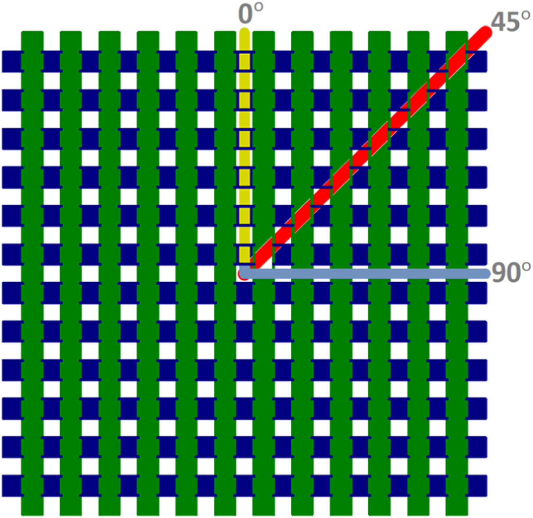
Ear formation is shown in a symmetrical semi-sectional form in the figures below. At a specimen temperature of 159°C and a holding pressure of 0.4 MPa, the effect of different depths on ear formation was given as a top view (Figure 4). As the part depth increased, the final diameter dimension decreased, and earing occurred in four regions (45°, 135°, 225°, and 315°). At a depth of 20 mm, the ear size is very close to the initial diameter. However, at 30 mm depth, the diameter variation of the horizontal and vertical axes of the specimen was maximum. When the depth was 20 - 25 - 30 mm, respectively, the ear was found to be 3.0 - 4.5 - 6.0 mm, respectively. Effect of depth on earing defect (T: 159°C - V: 90 mm/min - P: 0.4 MPa).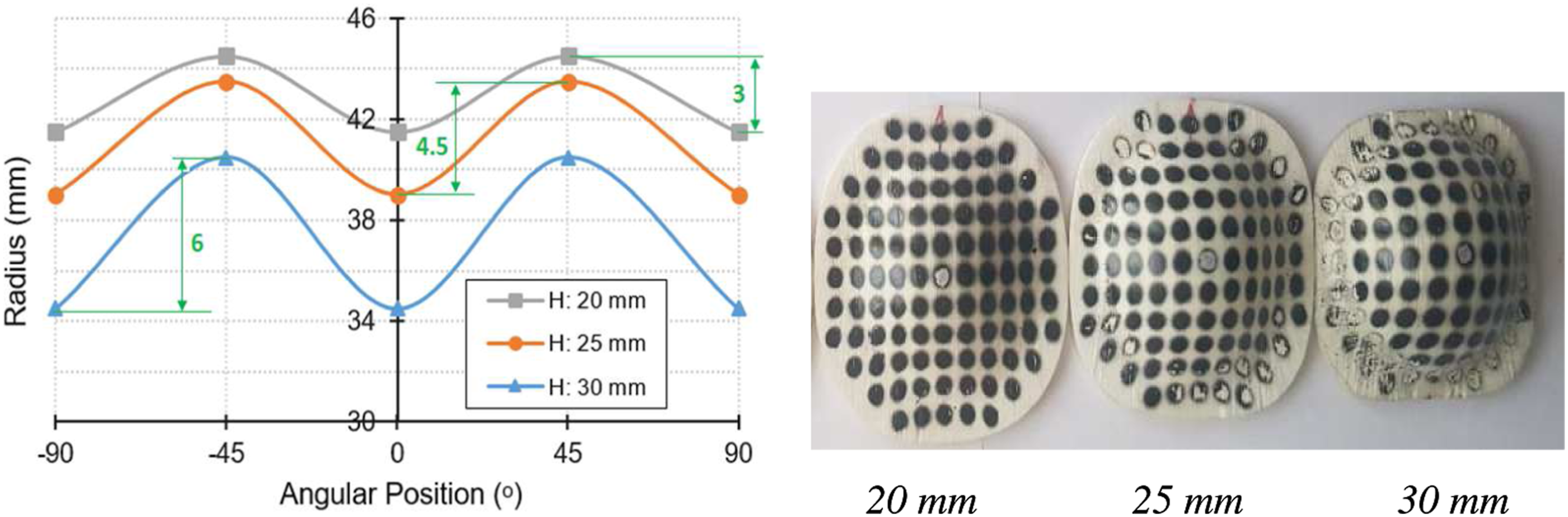
The variation of earing at different temperatures in tests with holding pressure of 0.4 MPa, and depth of 25 mm is shown in Figure 5. It was observed that the final diameter of the specimen drawn at the melting temperature decreased more than those in the tests performed at crystallization and softening temperatures. Residual stresses accumulated in the composite structure during forming cause some stretching of the part when the punch is brought back. Increasing the specimen temperature reduces this effect. In addition, Lee and Song,
17
who modeled the effects of thermal expansion and elastic modulus on glass fiber reinforced composites, announced that the shrinkage behavior of the composite material increased as the temperature increased. Concordantly, it is seen in Figure 5 that the shrinkage occurs inversely proportional to the temperature. After deep drawing at 124, 159, and 169°C specimen temperatures, the ear values were measured as 4.5, 5.0, and 5.5 mm, respectively. Effect of specimen temperature on earing defect (V: 90 mm/min - P: 0.4 MPa - H: 25 mm).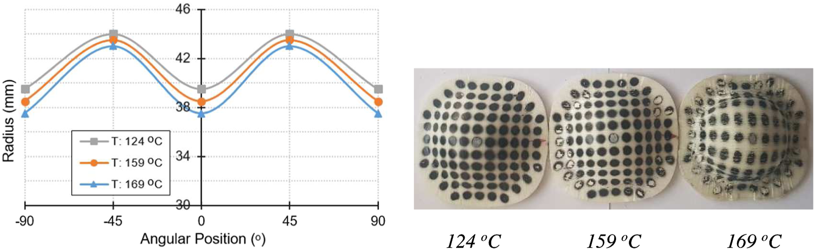
In Figure 6 and Figure 7, the effects of different holding pressures and punch speeds on earing are given. Ear formation according to the angular position is shown on specimens which are deep-drawn at 159°C and 25 mm depth. When the punch speed was 90 mm/min, the final diameter value of the flange part increased as the circumferential yield strength decreased with the increase of the holding pressure, but the earing amount did not change. Suresh and Kumar
11
reported similar findings in their study. They explained that the increase in holding pressure increased the radial tensile stress and thus caused an increase in flange diameter. Effect of holder pressure on earing defect (H: 25 mm - T: 159°C - V: 90 mm/min). Effect of punch speed on earing defect (P: 0.4 MPa - H: 25 mm - T: 159°C).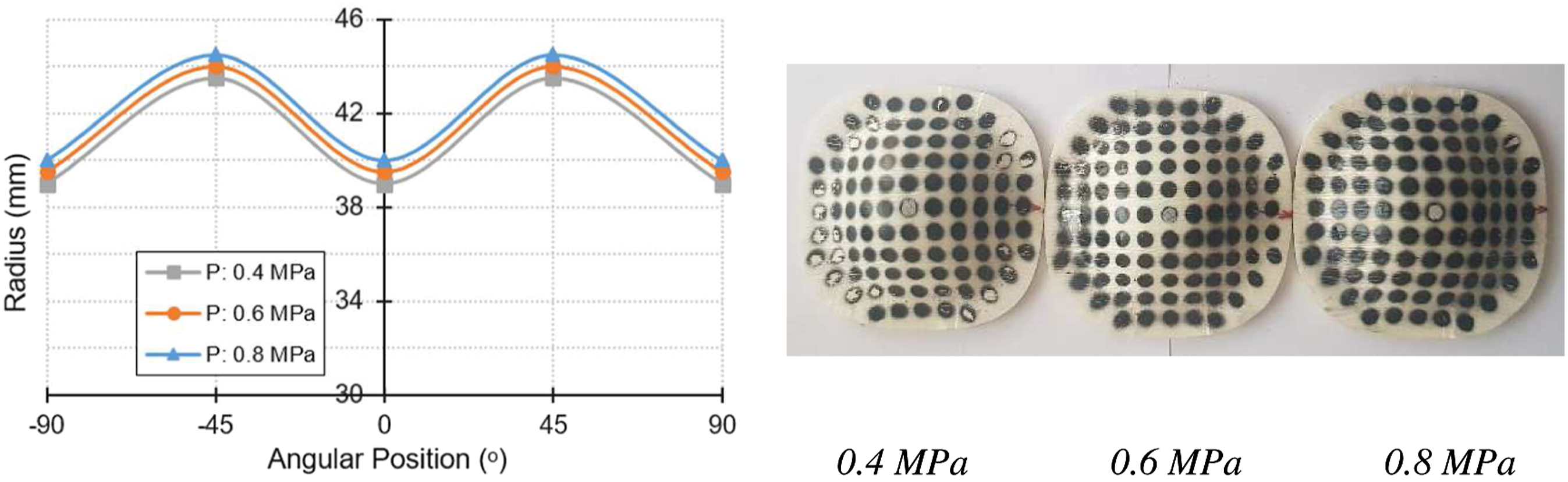
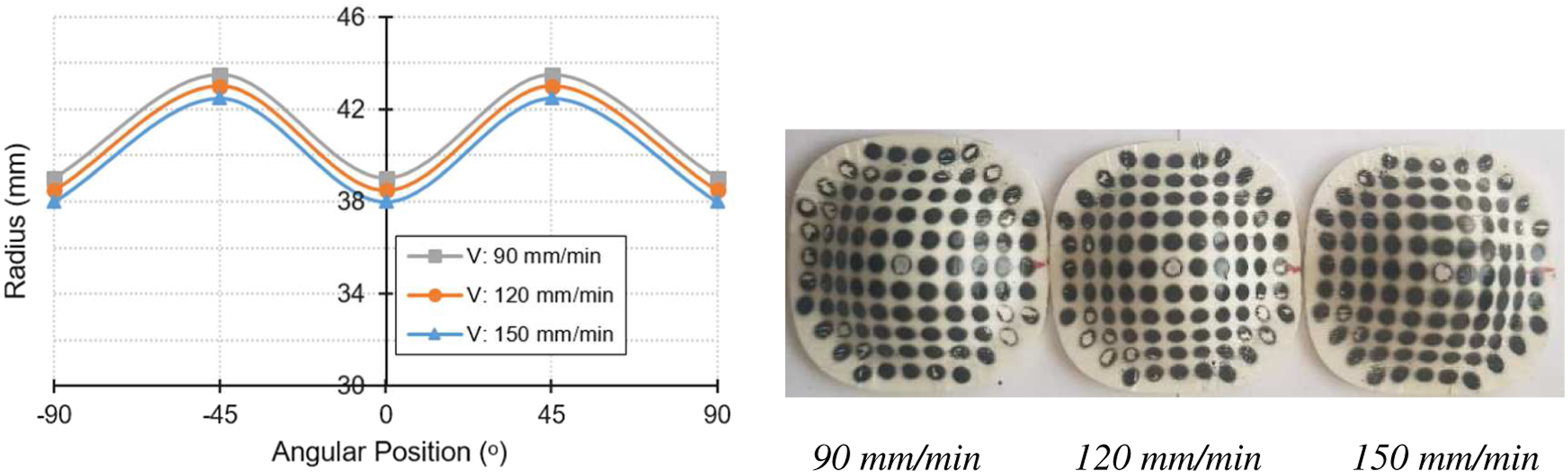
While the holding pressure was 0.4 MPa, increasing the punch speed decreased the large and small diameter values. However, the ear size did not change as the difference between them remained constant. The ear size remained constant at 9 mm although the holding pressure and punch speed changed. It was clearly seen that large diameter values occur in regions of 45°. It was determined that the ear size change was mainly a result of tool (punch/die) geometries and material structure. Since the stroke depth of the punch causes a geometrical change, ear formation is affected accordingly.
Thickness distributions at 0° and 45° sections of the part according to forming parameters
Deep drawn parts were cut by taking 1/8 sections from 0° and 45° axes. Five points (α:0°/30°/60°/curvature/90°) were marked on both axes (0 and 45) using an angle gauge. Curves were created with the thickness values measured from these points. The generated curves are given in Figures 9–12. The left region of the figures shows the thickness values read over the 0° section and the right region shows the values taken from the 45° section. The measuring points on the specimen are shown in Figure 8. When the thickness measurements were evaluated, it was revealed that there was a geometric difference between 0 and90° and ±45° directions in relation to the thickness change in the part. Measuring points and axes.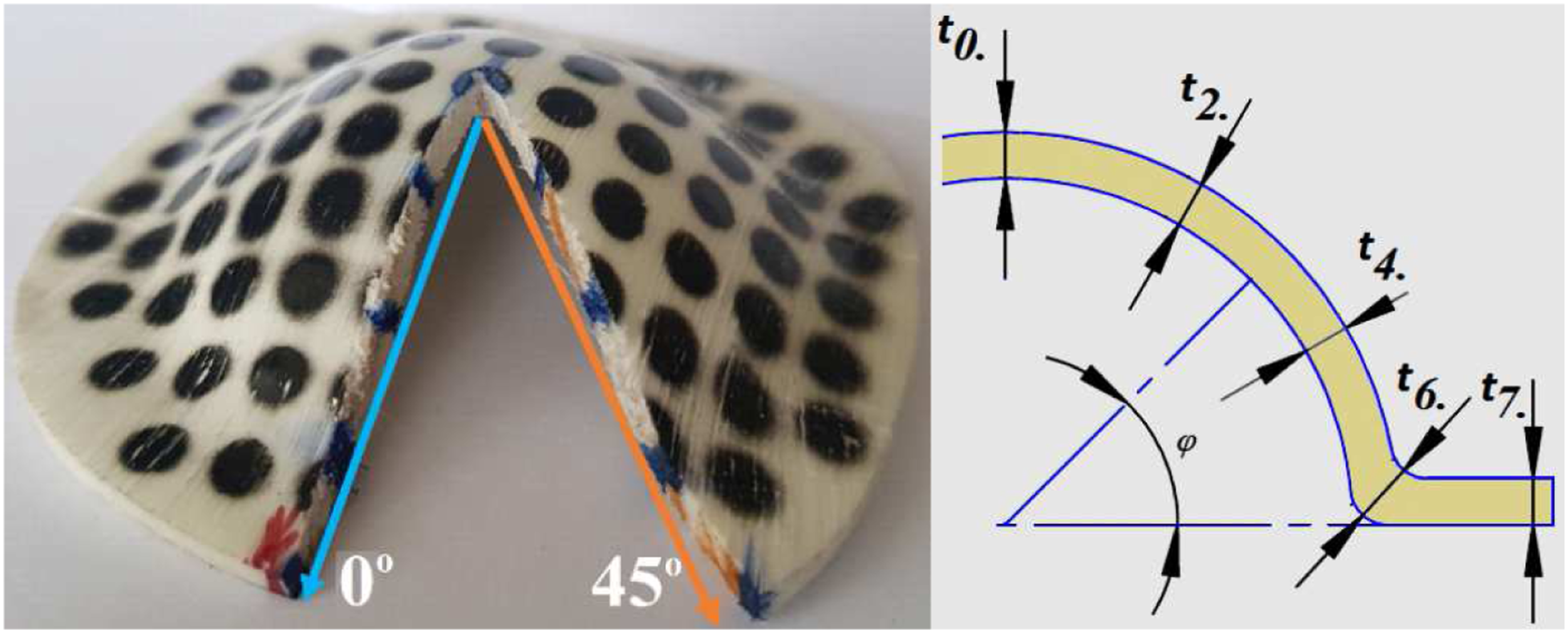
The effect of different depth values on thickening is shown in Figure 9 under the conditions of specimen temperature 159°C, punch speed 90 mm/min and holding pressure of 0.4 MPa. Due to the anisotropic nature of the composite laminate, the elongation behavior is irregular and this leads to inhomogeneous deformations. With the increase in the part depth, the thickening in the arcuate region decreased, but there was no significant change in the other parts. The thickness increase in the 0° section was greater than at all points on the 45° section. The least thickness variation occurred at 25 mm depth. The highest thickening occurred in the arc (t6) region. As in the study of Mao et al., in this study, the probability of damage to the upper and lumbar regions of the specimen increased as the depth increased.
6
Effect of drawing depth on part thickness distribution (T: 159°C - V: 90 mm/min - P: 0.4 MPa).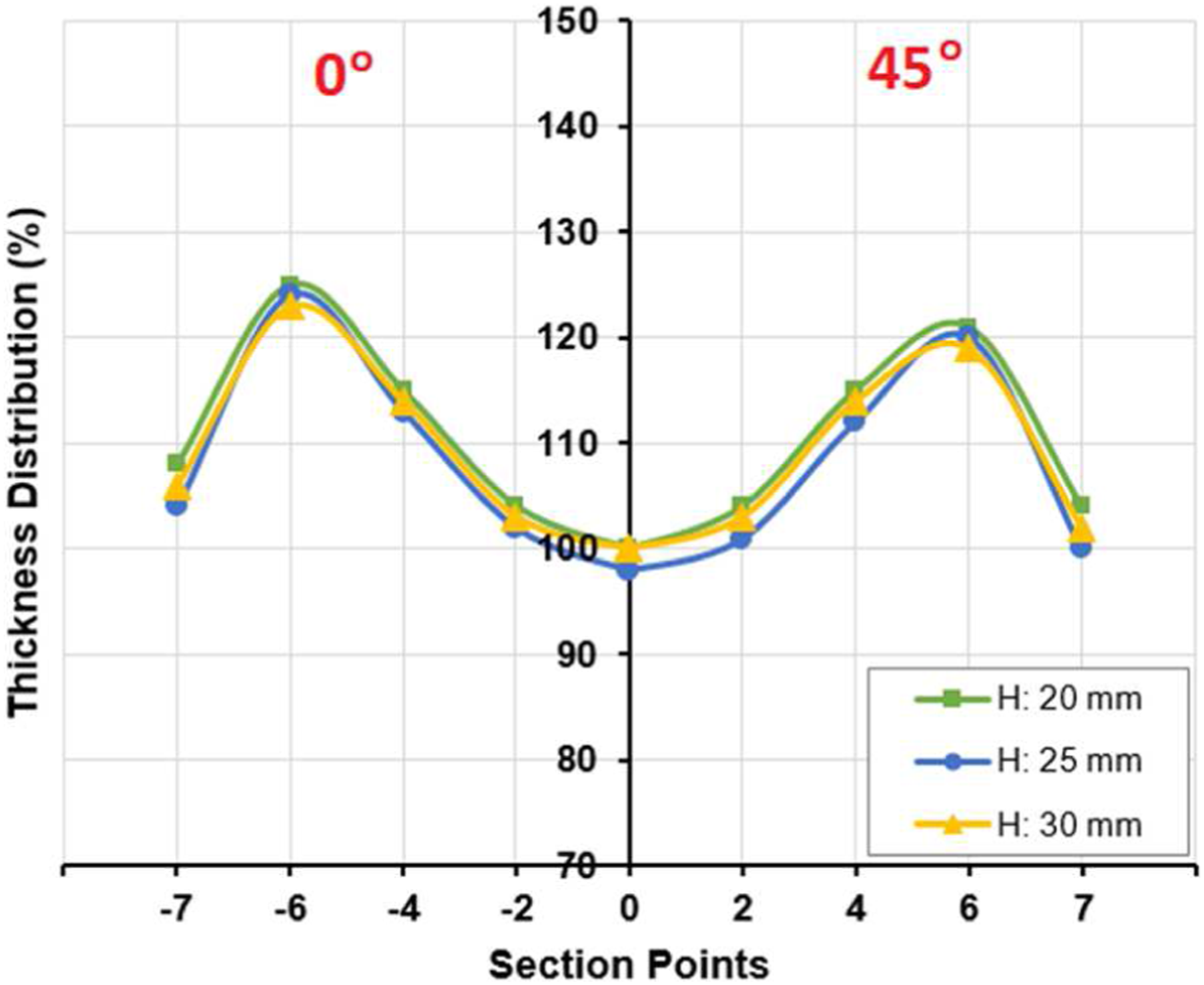
The effect of different specimen temperatures on the thickness change of deep drawn specimens at 90 mm/min punch speed, 0.4 MPa holding pressure and 25 mm depth is shown in Figure 10. It was determined that the most important parameter affecting the change in part thickness was the specimen temperature. Therefore, the rapid transfer of the specimen from the furnace to the mold and the closing speed of the mold are important to reduce the heat loss of the part. As the specimen temperature increased, the thickening tendency decreased in both 0° section and 45o section. It was observed that the t0 and t2 regions were thinned when the specimen was drawn deep at the melting temperature, but thickening was detected in the t4 region. The most significant difference between 0° and 45° sections was detected at t7. As the temperature increased, the applied holding pressure became more effective, and the flange thickness decreased at different rates in both the 0° section and the 45° section. However, the flange thickness between the sections decreased as the specimen temperature increased. As in the research of Mattner et al. thinning occurred because the mechanical behavior of the polymer weakened in the forming process around the melting temperature.
7
The temperature had the greatest effect on part thickness compared to other experimental parameters. The matrix element of the composite laminate examined in this study, polypropylene, is a thermoplastic type that has a semi-crystalline molecular structure at room temperature. Depending on the degree of crystallinity of thermoplastics, their thermal and mechanical properties change.
18
When the composite laminate was heated, the crystal structure of polypropylene became irregular, the polymer-fiber interface bonding strength weakened, and its atomic structures became amorphous as it approaches the melting temperature. As the temperature increased, the points between the center and the 45-degree region became too thin, in direct proportion to the force exerted by the punch on the laminate along its hemispherical curve. Along the continuation curve of the punch, as the composite laminate was partially free in the mold cavity up to the flange region, the fibers were able to be displaced and the distance between the layers increased and the thickening occurred at the points close to the mold radius. However, the crystalline structure of the cooled composite laminate was re-formed, the yield strength increased at the crystallization temperature, the elongation decreased, and thus the resistance to forming deformation improved. Therefore, as the specimen temperature decreased, the thickness distribution was more homogeneous, but the shear mechanism caused delamination and the thickness increased in the final part. Effect of laminate temperature on part thickness distribution (V: 90 mm/min - P: 0.4 MPa - H: 25 mm).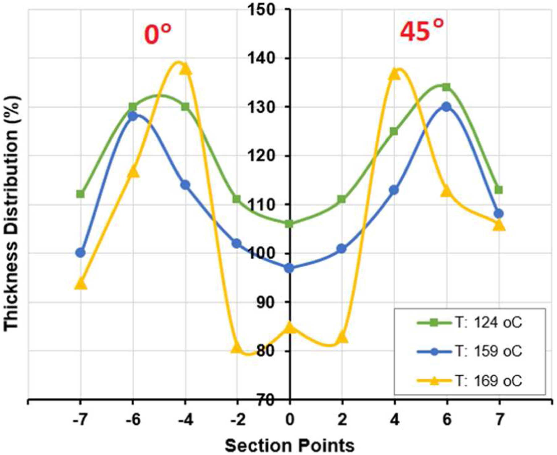
The effect of change in holding pressure on thickening is shown in Figure 11 (depth: 25 mm, specimen temperature: 159°C and punch speed: 90 mm/min). When the thickness change is examined; As the holding pressure increased, the thickening decreased in the flange region (t7), while the thickening increased in all other regions. It was determined that the highest thickening in the 0° section was in the curve region (t6). The least thickness variation occurred in the region that contacts the apex of the hemispherical punch, that is, at the thrust center (t0). At t0, t2, and t4 regions, the thickening in the 45° section increased less than in the 0o section. The t6 region thickened at the same rate, while the t7 region thickened more. In their study on the forming of sandwich panels Harhash et al. reported an increase in thickness from the center to the skirt along a section in deep-drawn material up to 25 mm and a thinning of the flange.
19
This determination fits the thickness variation profile shown in Figure 12. Since the pressure is applied to the plate from the flange area between the holder and the mold, the delamination in this region decreased as the holding pressure increased. Effect of holding pressure on part thickness distribution (H: 25 mm - T: 159°C - V: 90 mm/min). Effect of punch speed on part thickness distribution (P: 0.4 MPa - H: 25 mm - T: 159°C).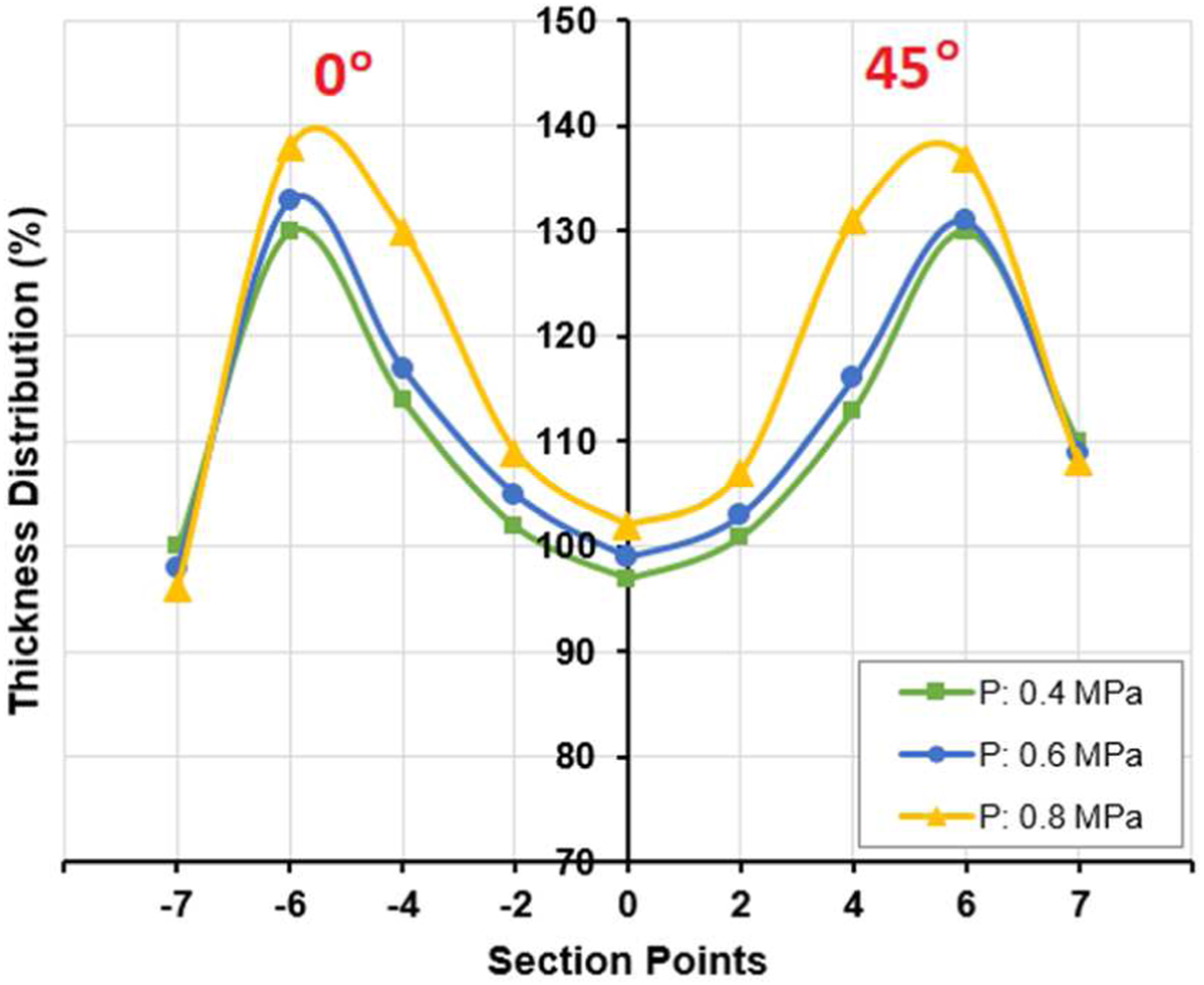
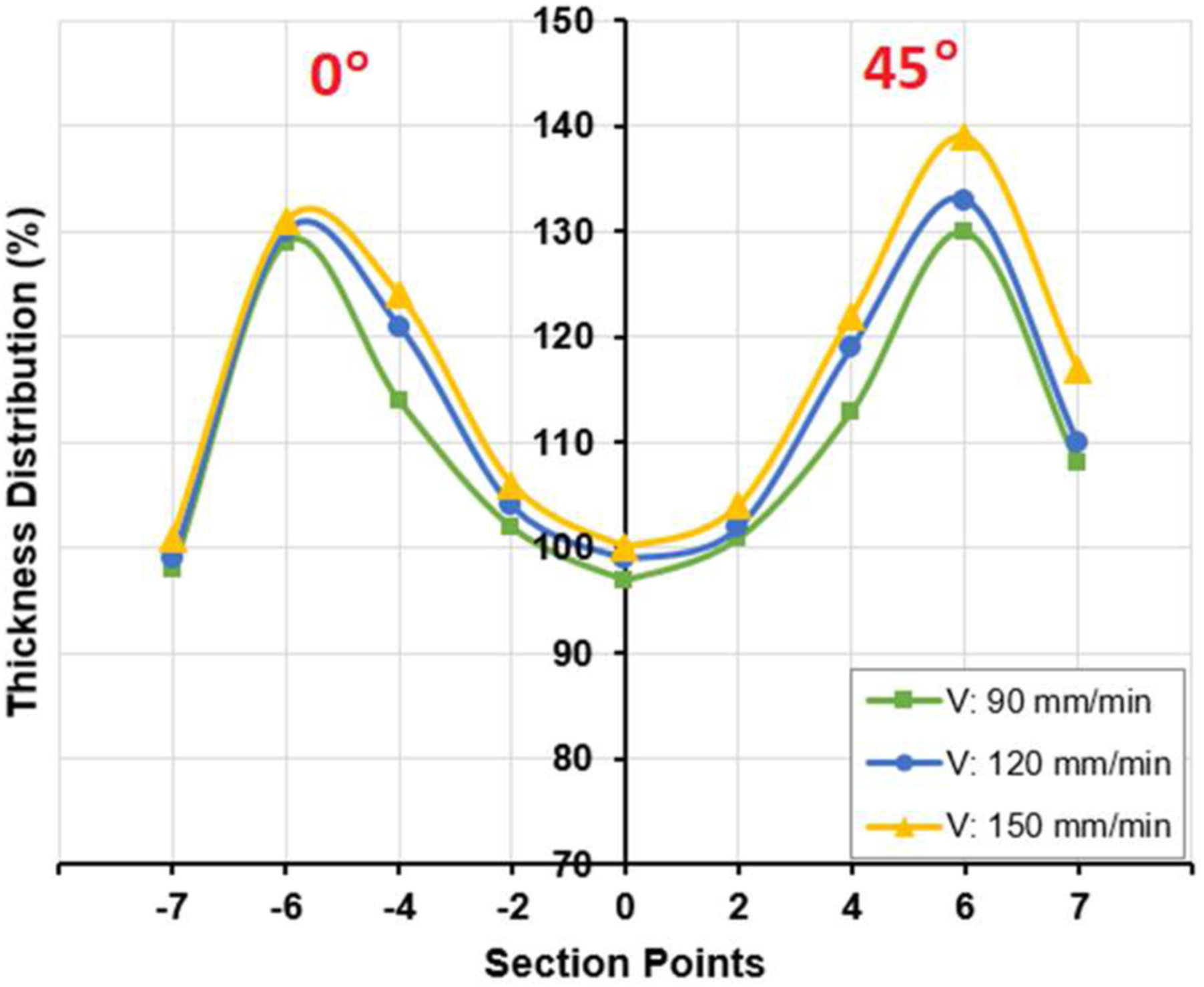
The effect of punch speed on thickness variation is shown in Figure 12 at holding pressure of 0.4 MPa, depth of 25 mm, and specimen temperature of 159°C. Thickening was least at a punch speed of 90 mm/min, but at 150 mm/min, thickening was greatest at all points of the part. The thickening of the flange and curvature on the 45° axis was greater than on the 0° axis. These findings are consistent with the results in the study of Alcock et al., and the intraply shear behavior of the fiber seems to be the reason for the increase in thickness in this area. 16 In addition, it was observed that the forming speed of 150 mm/min adversely affected the surface quality of the part.
Conclusions
In this study, ear formation and thickness variation defects in deep drawing of continuous glass fiber reinforced polypropylene composite laminates by thermoforming were investigated. The effects of drawing depth (20, 25, 30 mm), specimen temperature (124, 159, 169°C), holding pressure (0.4, 0.6, 0.8 MPa), and punch speed (90, 120, 150 mm/min) on deformation were investigated. The compatibility of the parameters with each other significantly affects the surface layer of the part. It was determined that the ear formation increased with the increase of the drawing depth. It was observed that the temperature affected the fluidity of the specimen between the mold and the holder, thus causing a significant change in the specimen flange diameter and earing amount. It was revealed that the holding pressure and punch speed variations caused a variation in flange diameter but did not affect the amount of earing. An inhomogeneous thickness distribution was detected in the deep-drawn pieces. It was determined that the formed laminates showed a tendency to thicken due to the interface separation. It was found that the most important parameter affecting the part thickness was the plate temperature, and the temperature increase decreased the thickness difference. It was observed that the most thickening occurred in the curve region.
Footnotes
Acknowledge
We would like to thank the Scientific and Technological Research Council of Turkey (TÜBİTAK) for its support within the project coded 218M194 for the supply of composite materials used in this study.
Declaration of Conflicting Interests
The author(s) declared no potential conflicts of interest with respect to the research, authorship, and/or publication of this article.
Funding
The author(s) disclosed receipt of the following financial support for the research, authorship, and/or publication of this article: This work was supported by the we are grateful to the Projects and Scientific Investigation of Gazi University (GU-BAP) for providing the tools used in the experiments within the scope of the project coded 07/2018-15 and TÜBİTAK (218M194).
Data Availability Statements
Datasets created and/or analyzed during the current study are available from the corresponding author if request is accepted.