
Abstract
The spring-in behavior of woven carbon fiber/polycarbonate thermoplastic composite is investigated by both the experiment and simulation ways. These thermoplastic composite plates are thermoformed into V-shaped structures, and the final bending angle is measured after demolding. In the finite element simulation to describe the thermoforming and spring-in behavior of the composite, the discrete approach is adopted to simulate the behavior of woven carbon fabric and combined with a resin model. The results from both the experiment and the simulation indicate the spring-in behavior of this thermoplastic composite. For [(±45)]6 blanks, the spring-in angle is around 2.60° for a 60-degree V-shape and around 1.72° for a 90-degree V-shape. For [(0/90)]6 blanks, the spring-in angle is around 2.38° and 1.19° for 60-degree and 90-degree V-shapes, respectively. The [(±45)]6 blank always has a slightly higher spring-in angle than the [(0/90)]6 blank, even though the difference is small. The finite element results show 6% to 12% differences with the experimental values if the spring-in angle is used, and the error is less than 0.6% when the bending angle is compared. By using the present finite element analysis, the results indicate that the stacking sequence could have an evident effect on the spring-in angle, and symmetric laminates have less spring-in effect as compared to their unsymmetric counterparts.
Introduction
Because composite materials have high values of stiffness/weight and strength/weight, they offer the potential for weight saving in structural components applied in automobiles, aerospace, and other industries. Among them, thermoplastic composite materials have recently gained much attention due to their shorter processing time, recyclability, and unlimited shelf life in contrast to thermoset composite materials. However, higher material cost and viscosity are their disadvantages. Because of these, semi-finished products like thermoplastic composite sheets are a better choice for subsequent forming processes. For forming methods, there are a lot of variations such as matched-die forming, diaphragm forming, and hydroforming, 1 and the choice is dependent on the capital investment and the quality of the product. 2 Among these forming methods, thermoforming or matched-die forming is a suitable automated manufacturing process to make complicated components analog to the deep drawing process for metals.
Thermoforming is a high-deformation rate process and involves heating the thermoplastic sheet to a temperature range at which it becomes soft, generally between the glass transition temperature and the melting temperature. After heated, the sheet is deformed into the desired shape with molds and then solidified. Because it is a simple and fast process with the potential to be automated, thermoforming is a popular manufacturing process. For example, Striewe et al. 3 thermoformed three-dimensional hat profiles, which were lately bonded with closing plates into crash boxes, from woven glass fabric/polyamide six thermoplastic composites at around 270°C. These same thermoplastic composite sheets were thermoformed into a downscaled battery tray for a plug-in-hybrid automotive vehicle at 260°C for the blank and 110–120°C for the tool. 4 Maron et al. 5 locally thermoformed semi-finished thermoplastic composite tubes into shafts with integrated flanges at a temperature domain above the melting temperature.
To obtain thermoformed parts with high quality, the forming process parameters and the temperature-related parameters need to be carefully chosen. Lee et al. 6 thermoformed glass fiber-reinforced polypropylene composites with different cooling rates and investigated the related mechanical properties. Han et al. 7 showed that the optimal thermoforming conditions for carbon fiber-reinforced polyphenylene sulphide laminates could be obtained according to their effects on the finished dimensions of V-shaped parts. The effect of the stacking sequence of glass fiber-reinforced polypropylene composite laminates was studied to prevent wrinkling in the deep drawing process. 8 The effects of gripper location and blank geometry on the thermoforming behavior of carbon-fiber fabric/polyphenylene sulfide (PPS) composite sheets were investigated. 9 An experimental investigation including various thermoplastics, the fixed method of mold, and the fiber orientation of thermoplastic composite blanks was demonstrated to show their importance in the thermoforming of parts with complex double curvatures. 10
The dependency of thermoforming on temperature, forming rate, blank holding pressure, material, and cooling rate makes it a highly complicated, multivariable, and nonlinear process. Since it is difficult to have theoretical modeling, finite element simulation is a good choice to investigate the effect of the above-mentioned parameters on the final products. Currently, the continuous approach, discrete approach, and semi-discrete approach are three methods to simulate the thermoforming behavior of thermoplastic composites. Continuous approaches11–13 accounted for thermoplastic composites as continuous materials represented by shell or membrane elements to consider the anisotropic behavior and the large shear and bending deformation. In this approach, the sliding and rotation between fibers were not considered. In contrast, the discrete approach 14 used a micro-mechanical model for woven fabrics considering fiber reorientation, viscoelasticity, and the trellis mechanism of yarns. In combination with resin, this approach could describe the thermoforming behavior of thermoplastic composites. However, a lot of fiber parameters needed to be input and making this approach cumbersome. The semi-discrete approach15,16 tried to compromise the above two approaches and developed special continuous elements affected by micro-mechanical behavior. However, developing this special element is not a straightforward task.
In the discrete approach, the main part is to treat the interaction between yarns in fabrics. Charmetant et al. 17 proposed a hyperelastic model of a woven unit cell for textile composite reinforcements to compute the geometry of the deformed cell and validated it by biaxial tension and in-plane shear test. De Luycher et al. 18 proposed a specific hexahedral finite element made of segment yarns and accounted for their transverse properties by a hyperelastic constitutive law for composite reinforcements. Based on a hybrid unit-cell modeling approach combining shell and beam elements for the fabric reinforcement, Schommer et al. 19 could predict fiber orientation, wrinkling, and occurring defects during the non-isothermal thermoforming process of thermoplastic composites. Sidhu et al. 20 modeled a textile preform as a mesh of truss elements allowing scissor and slide of tows and shell elements accounting for inter-tow friction and fiber angle jamming, and this model was demonstrated in the stamping of a preform by a spherical punch.
Spring-back behavior is common and concerned in metal workpieces because of large deformation. After the manufacturing process of composite parts, two types of undesired shape deformation may occur due to residual stresses. The first type is called warpage which rises in flat laminates. The second type is called spring-back or spring-in behavior for angled laminates depending on the positive or negative angle deviation. Pereira et al. 21 investigated the spring-in behavior of L-shaped carbon/epoxy composite structures as a function of time and found that the spring-in effect was released over time. The spring-in behavior of an L-shaped carbon/epoxy composite was investigated by a finite element model considering both the thermo-chemical and thermos-mechanical phenomena 22 and it concluded that only the layup sequence affected the spring-in as compared to the thickness and the corner radius. Similar spring-in behavior was found on C-section specimens23,24 and L-shaped parts 24 made of thermoset composites. For thermoplastic composites, Padovec et al. 25 indicated the spring-in phenomenon of L sections of carbon composites with PPS thermoplastic matrix by the analytical, numerical, and experimental approaches, while spring-back angle was found in the plates with single curvature made from the same thermoplastic composite. 26 Bernd and Jasmin 27 bent a glass fiber reinforced polyamide six with three layers of twill fabric into a V-shape with a 90-degree angle and revealed the spring-in or spring-back behavior depending on the bending radius, normal pressure, velocity, and dwell time.
For thermoset composite materials, the spring-in behavior was found in several references. For thermoplastic composite materials, very few works are revealing the positive or negative angle deviation. In addition, this spring-in behavior is seldom simulated and investigated. In this work, the woven carbon fiber fabric/polycarbonate composite is used and its spring-back or spring-in behavior after thermoforming is focused. To predict the behavior of this thermoplastic composite by finite element simulation, the discrete approach was adopted to simulate the behavior of woven carbon fabric and combined with a resin model to describe its thermoforming behavior. Two types of blanks, [(±45)]6 and [(0/90)]6, were thermoformed into V-shaped structures with an angle of 60 degrees or 90 degrees. The spring-in angle is measured and compared between the experiment and the simulation. The result confirms the spring-in behavior of the thermoplastic composite and verifies the finite element simulation. Then, the simulation is used to discuss the effect of the stacking sequence of the composite and the bending angle.
Material and experiment
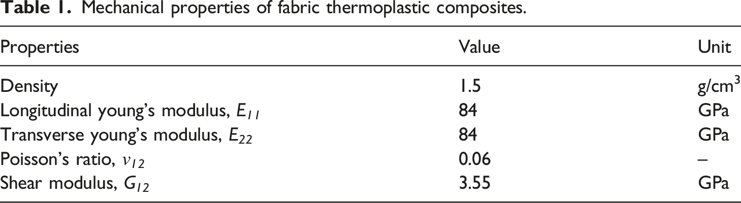
Mechanical properties of fabric thermoplastic composites.
Mechanical properties of TC-33 carbon fibers.
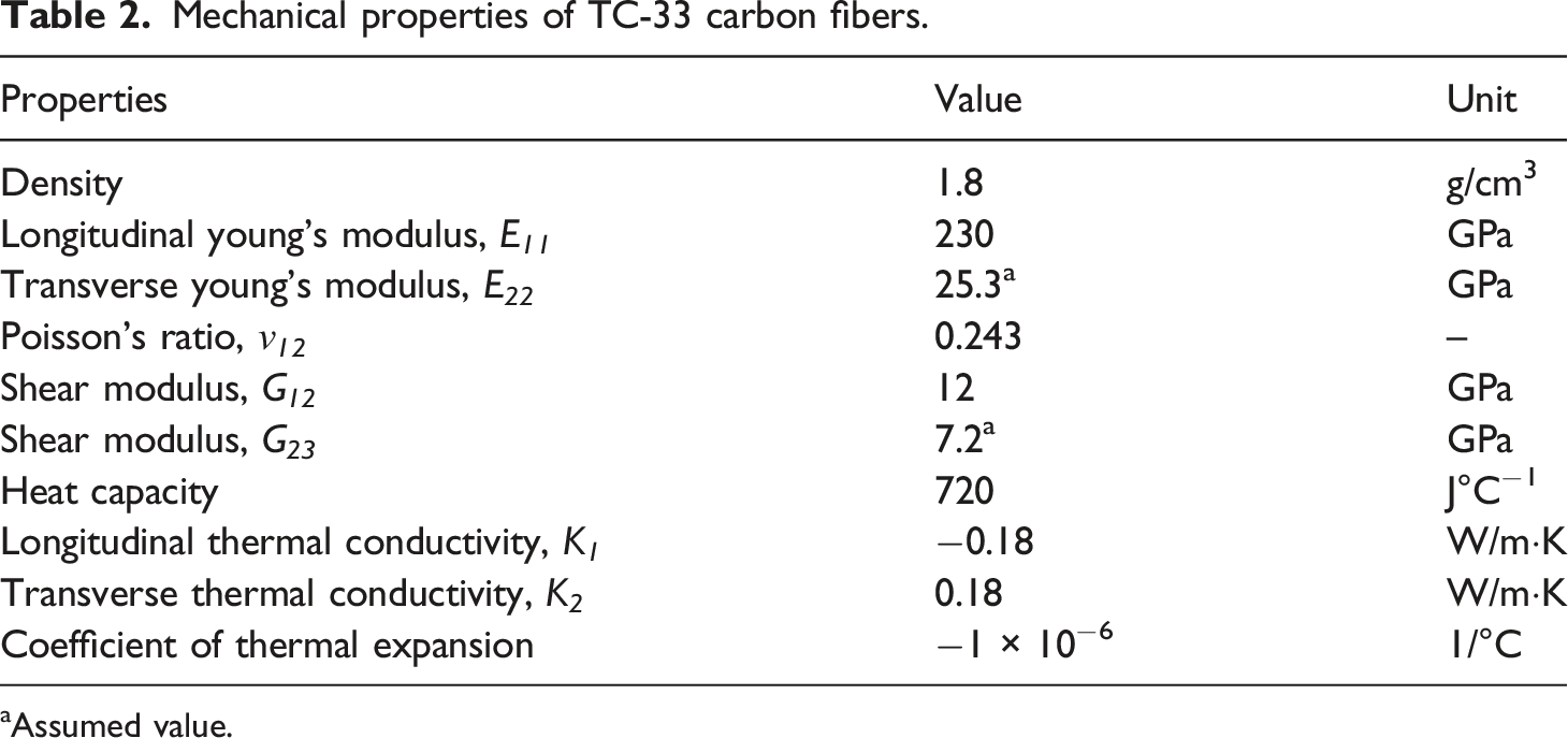
aAssumed value.
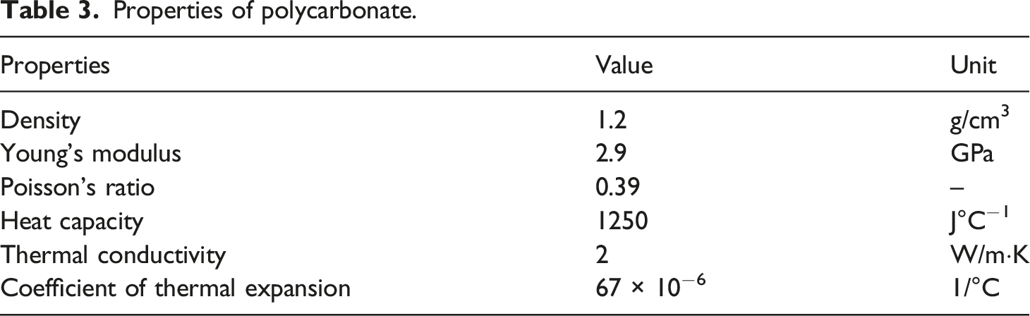
Properties of polycarbonate.
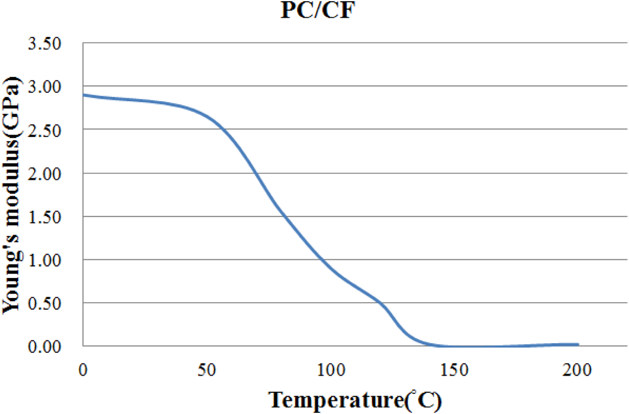
Young’s modulus of polycarbonate with respect to temperature.
The above thermoplastic composite plates with the dimension of 220 × 120 × 1.2 mm were used as blanks. These blanks consisted of six layers of plain-woven fabric, and they were thermoformed into V-shaped structures. To investigate the effect of fiber angle, two types of fiber angle arrange were considered. One is denoted as [(0/90)]6, in which (0/90) represents one layer of plain-woven fabric/polycarbonate composite and the fibers are along 0 and 90 degrees. The other is denoted as [(±45)]6, in which the same six-layer composite is used and the fibers are along +45 and −45 degrees. In addition, there were two V-shapes considered. One is called a 60-degree V-shape, in which the final angle of the V-shape is 60 degrees and the punch depth is 50 mm. The other is called a 90-degree V-shape which has a final angle of 90 degrees and a punch depth of 40 mm. As an example, the punch and die for the 60-degree V-shape are shown in Figure 2. In addition, a blank holder was utilized. To select the thermoforming parameters, the blank temperature was changed from 180°C to 204°C, and the temperature of the punch and die was considered from 150°C to 175°C. The forming rate and the blank-holder pressure were 25 mm/s and 0.098 Pa (1 kg/cm2), respectively, and the final forming pressure was either 3.92 Pa (40 kg/cm2) or 4.9 Pa (50 kg/cm2). An infrared heater was employed to heat the composite blank, which was laid on the lower mold, to the desired temperature. After closing the mold with the final forming pressure, the system was kept for 1 hour without temperature control. Then, the temperature of the workpiece was about 100°C and it was demolded. After that, the workpiece was put on a table and naturally reduced to room temperature. Punch and die for 60-degree V-shape: (a) punch, (b) die.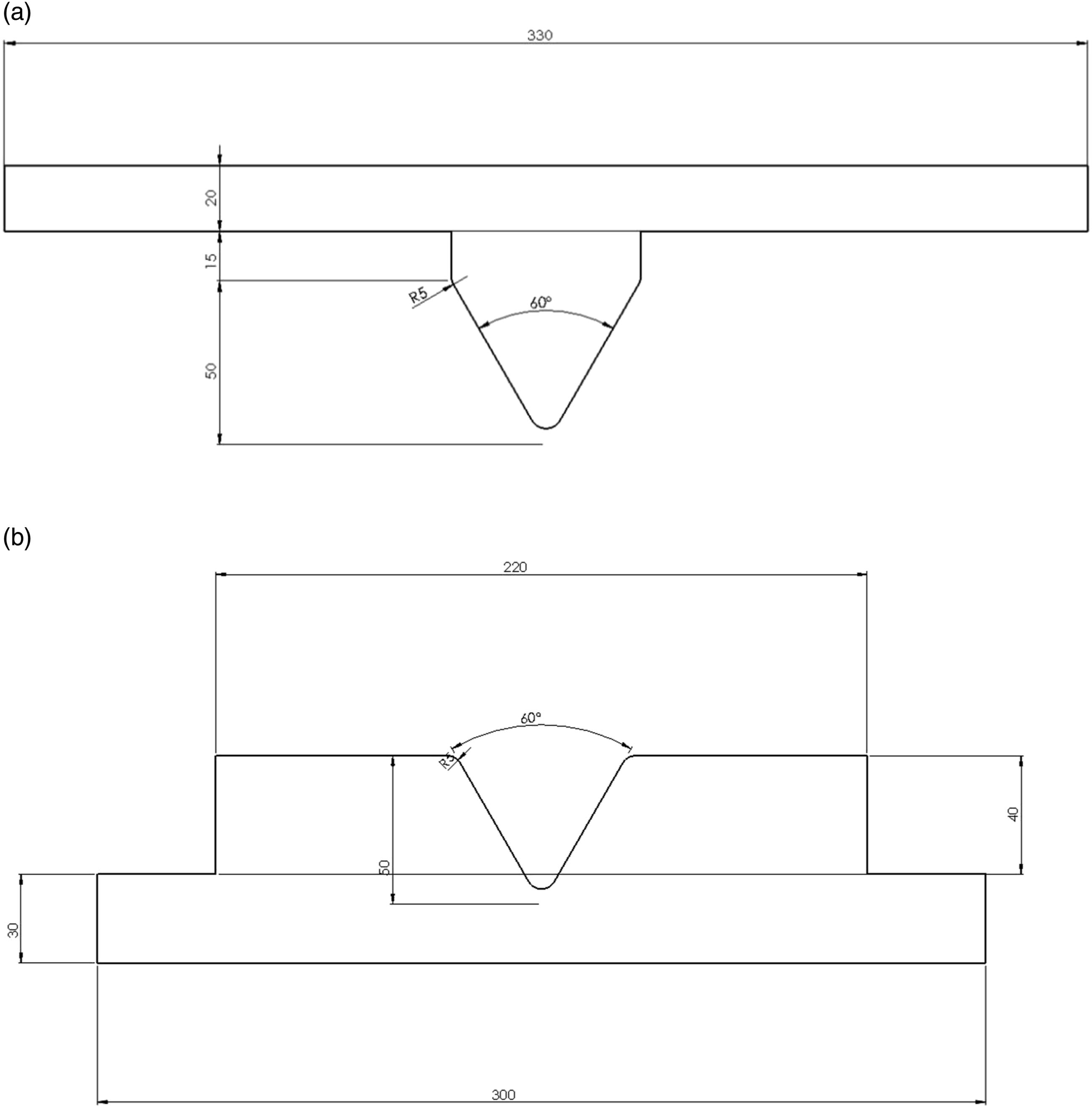
After several experiments, to avoid wrinkles and rough surfaces, the appropriate thermoforming parameters were selected as the blank temperature of 204°C, the mold temperature of 175°C, and the final forming pressure of 4.9 Pa. As the workpiece was set free on a table for enough time and its temperature was reduced to room temperature, the angle of the workpiece was measured by a Carmar VMM-1510D with a CCD camera for 2D measurement. This angle was obtained from two lines located at one end of the workpiece. Hence, there are two angles as shown in Figure 3. The angle at the left end is called Angle-1 and the other is called Angle-2 in this work. Angle-1 and Angle-2 measured for the final angle.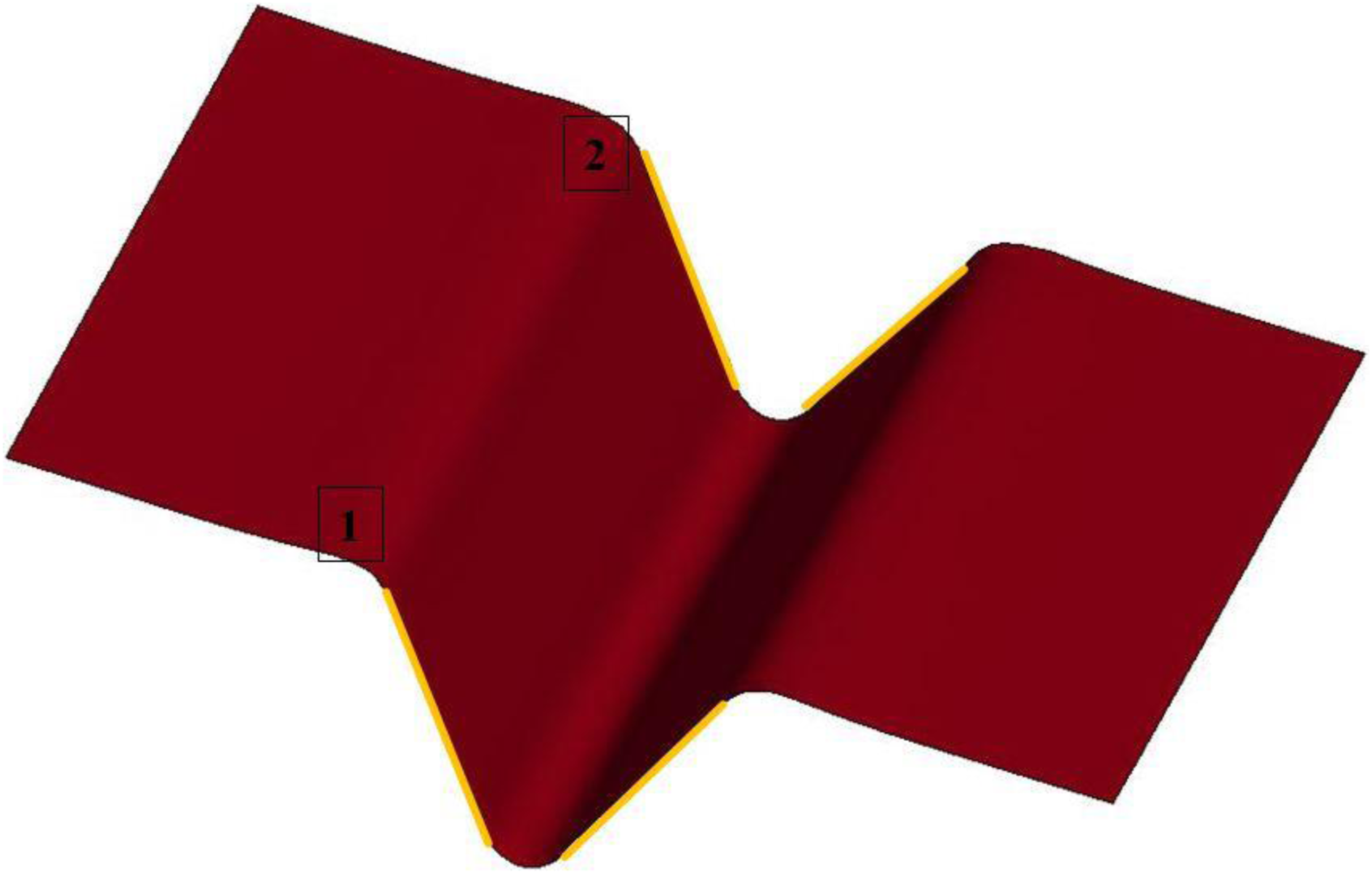
Finite element analysis
The finite element simulation for the thermoforming process was conducted by the explicit mode of LS-DYNA. In this simulation, the composite blank was treated as the combination of fiber fabric layers and resin layers. A discrete approach was applied to describe the deformation behavior of the fiber fabric. This discrete approach was implemented by a material model, MAT 234 in LS-DYNA, which was developed by Tabiel et al. 11 This model incorporated fiber crimping, trellising with the reorientation of the yarns, and the locking phenomenon in loose fabric. A Kelvin-Voight element and a Maxwell element without the dashpot were combined to represent the mechanical behavior of the yarn. It was valid for modeling the elastic and viscoelastic behavior of loose fabric. Some main parameters for the carbon fiber used in the present work were listed in Table 1. As for the resin of the thermoplastic composites, the material model, MAT 004 in LS-DYNA for elastic, plastic, and thermal analysis, was chosen to simulate the temperature variation of the resin during heat transfer process. In this work, the resin was assumed to be elastic, and its Young’s modulus was dependent on temperature as shown in Figure 1 to represent the effect from the consolidation process. The other necessary properties of the resin are shown in Table 2.
To simulate the deformation behavior of the blank, the six-layer thermoplastic composite laminates used in the present work were considered as one object meshed by one shell element along the thickness direction. In this shell element, there are five layers of resin and four layers of fiber fabric alternatively interlaced as shown in Figure 4. Since the thickness of the thermoplastic composite was 1.2 mm and the fiber volume fraction was 0.3, the layer thickness of resin and fiber fabric was 0.168 mm and 0.09 mm, respectively. Different numbers of resin layers and fabric layers were investigated and the result indicated that five resin layers and four fabric layers were better choices, which agreed with.
11
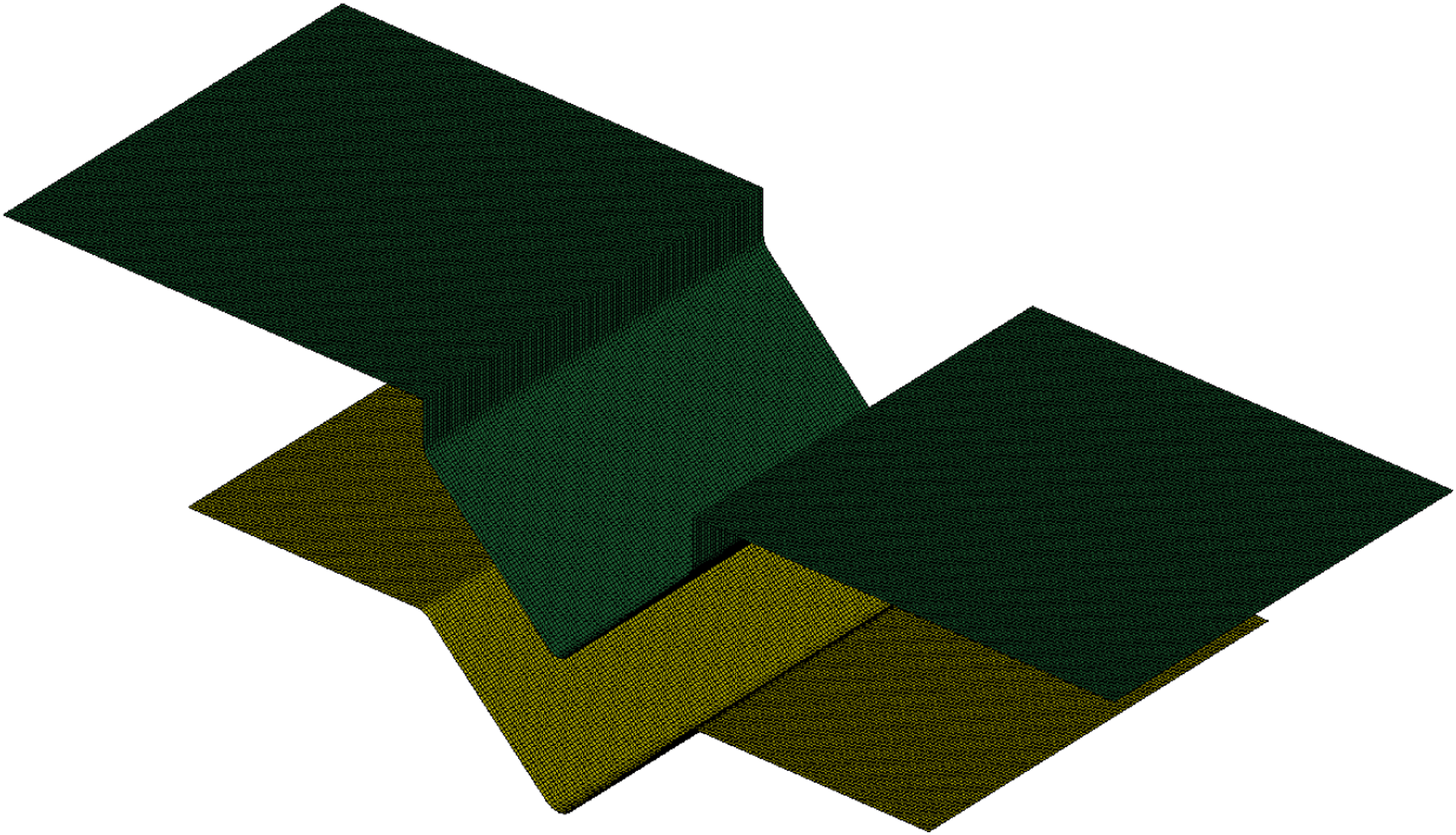
Full integration was chosen for each layer during the simulation. The size of the shell element was 1 × 1 mm, and the mesh for the V-shaped structure and the punch were shown in Figure 5. In this case, the punch, the die, and the blank holder were treated as rigid bodies with a density of 7.83 g/cm3, Young’s modulus of 210 GPa, and Poisson’s ratio of 0.3. These three parts were also meshed with shell elements with the size of 1 × 1 mm. The thermoforming parameters were the same as those described in the above section. To include the effect of the temperature difference of different parts, transient thermal analysis was coupled with structural analysis. At the end of the thermoforming simulation, all parts were reduced to 100°C. During the forming, the static and dynamic friction coefficients between the mold and the blank were set to 0.2 and 0.1, respectively. Combination of the fiber layer and resin layer for the composite shell element. Finite element meshes for the blank and the punch.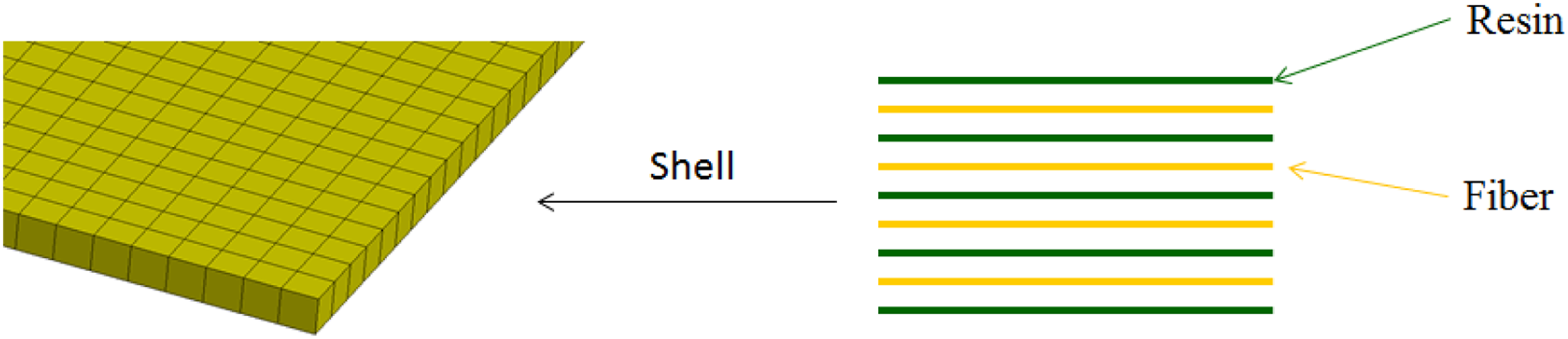
To simulate the spring-back or spring-in behavior of the V-shaped thermoplastic composite laminates, the demolding process was executed at the temperature of 100°C after the final forming pressure of 4.9 Pa for 1 hour. After demolding, the workpiece was set free and its temperature was naturally reduced to room temperature. Then, the final angle of the workpiece was measured. For metals, the spring-back process was generally simulated in an implicit mode. That is to say that an explicit analysis is for the forming process and an implicit analysis is for the spring-back process. However, due to the limitation of the material model of the fiber fabric, MAT 234, which could not be used in the implicit analysis, an explicit analysis was used to simulate the spring-back or spring-in behavior of the V-shaped thermoplastic laminates. After the thermoforming process, the file method was used to transfer all the necessary information about the element, the layer, and the integration into the spring-back simulation. Meanwhile, the punch, the die, and the blank holder were removed. Furthermore, the temperature of the workpiece was reduced from 100°C to 25°C, and the transient structure analysis was coupled with the thermal analysis. To reduce the dynamic effect of the explicit analysis, six points of the thermoplastic plate as shown in Figure 6 were constrained in the x direction. As shown in Figure 3, Angle-1 and Angle-2 of the deformed V-shaped structure were measured to represent the simulated final angle. Fixed points for the spring-back analysis.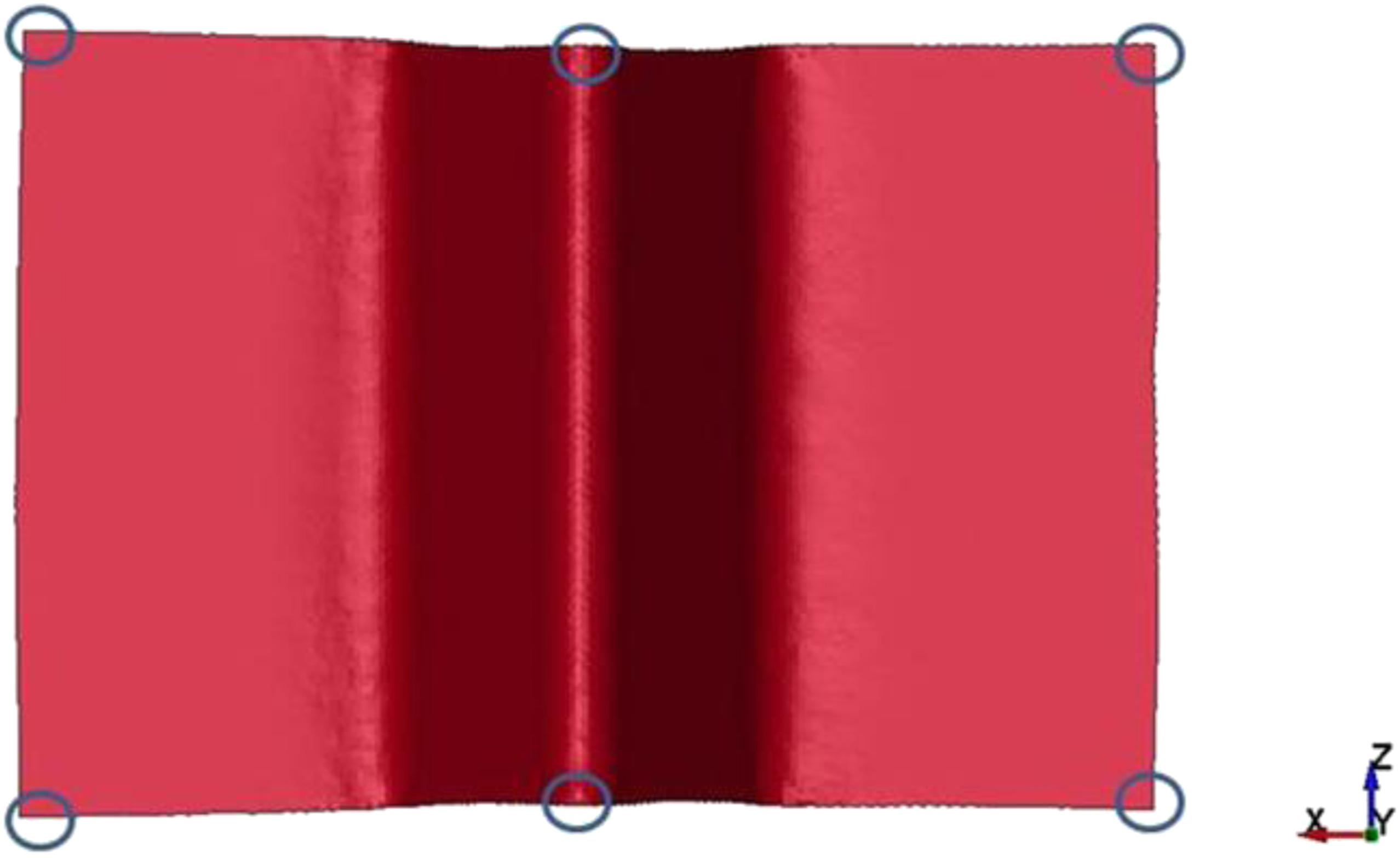
Results and discussion
Validation of the explicit spring-back analysis
Instead of an implicit analysis, an explicit analysis for spring-back behavior was selected in the present work, and it was verified by a metal example. This example
28
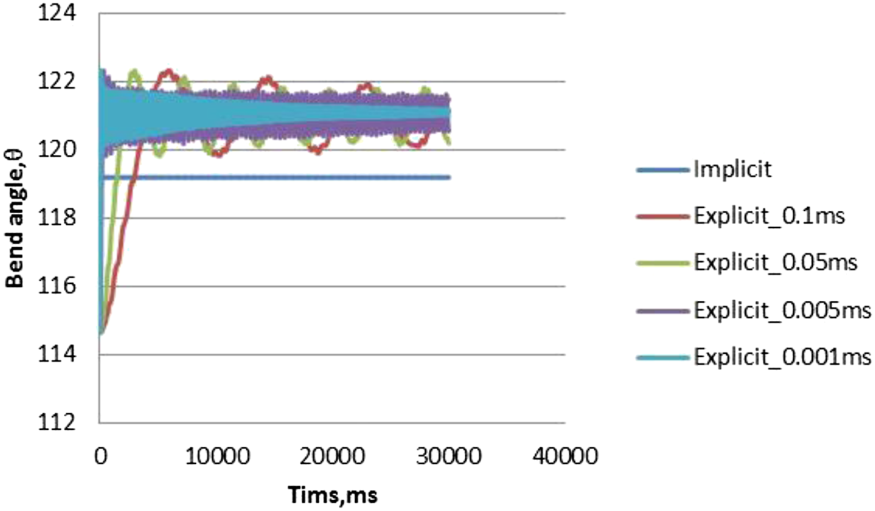
investigated the spring-back behavior of an aluminum tube with a length of 200 mm, an outer diameter of 30 mm, and a thickness of 2 mm under three-point bending with a span of 200 mm and a forming speed of 0.2 mm/s. The deformed area of the tube was meshed by the Belytschko-Tsay shell element with a size of 1.5 × 1.5 mm, and the other area was meshed by the same element with a size of 2.3 × 2.3 mm. Piecewise linear plasticity, MAT 24, was chosen to describe the elasto-plastic behavior of aluminum. In this example, the bending process was analyzed by an explicit mode and the spring-back process was simulated by either the implicit mode or the explicit mode. By using the explicit spring-back analysis, the deformed shapes are shown in Figure 7(a) and (b) for the bending angle before and after the spring-back, respectively. For the explicit analysis, different time steps from 0.1 ms to 0.001 ms were used. The final angle from the simulation is shown in Figure 8. From this figure, the final angle from the explicit analysis oscillates and the average value is used, while the implicit analysis has one constant value. As compared to the implicit result, the explicit result is 1.14% to 1.54% higher, and this may verify the explicit analysis for the spring-back behavior. As a reference, the experimental spring-back angle was 4.03 degrees and the present explicit analysis is around 4.5 degrees. Bending angle of the deformed aluminum tube: (a) before spring-back, (b) after spring-back. Explicit and implicit simulation results for the aluminum tube.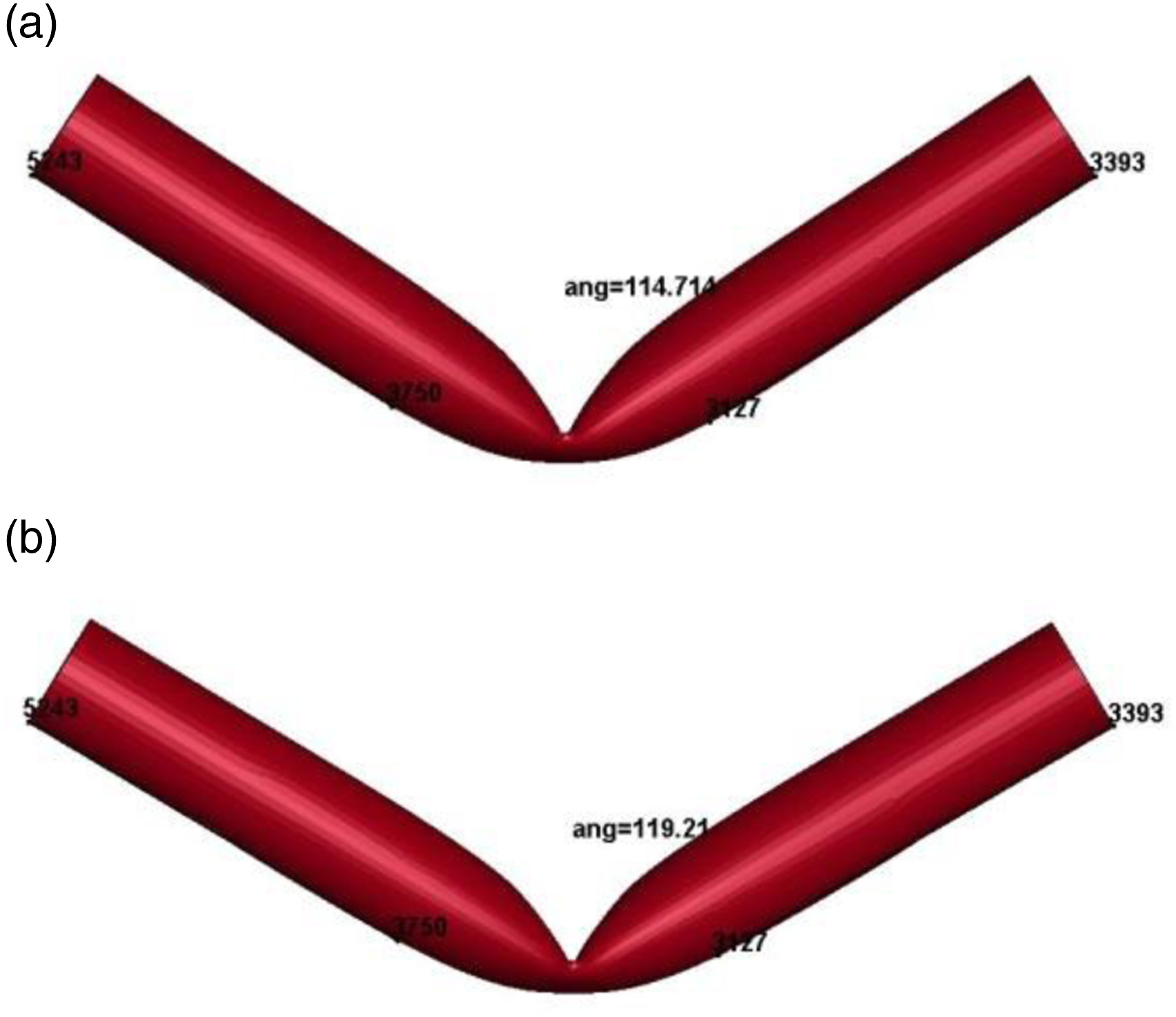
Comparison between experiment and simulation
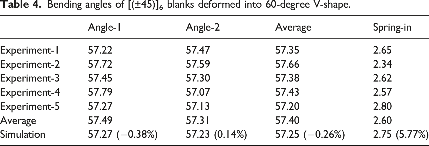
Take the [(±45)]6 blanks as an example that was thermoformed into a 60-degree V-shape. The simulation result for the final bending angle under explicit analysis with the time step of 0.001 ms was shown in Figure 9. In this analysis, the six points as shown in Figure 6 were fixed in the x direction, and the oscillation of the bending angle was dramatically reduced. The simulated bending angles after the thermoforming and spring-back processes are compared to the experimental results of five specimens in Table 4. As shown, the experimental bending angles of five specimens are consistent and Angle-1 is very close to Angle-2. Their average angle is 57.40°, and this means a spring-in behavior with an angle of 2.60°, instead of spring-back behavior. The simulated bending angle is 57.25°, which is −0.26% different from the experimental result. If the spring-in angle is compared, there is a 5.77% difference because the simulated spring-in angle is 2.75°. Explicit analysis for the final bending angle of the [(±45)]6 blanks. Bending angles of [(±45)]6 blanks deformed into 60-degree V-shape.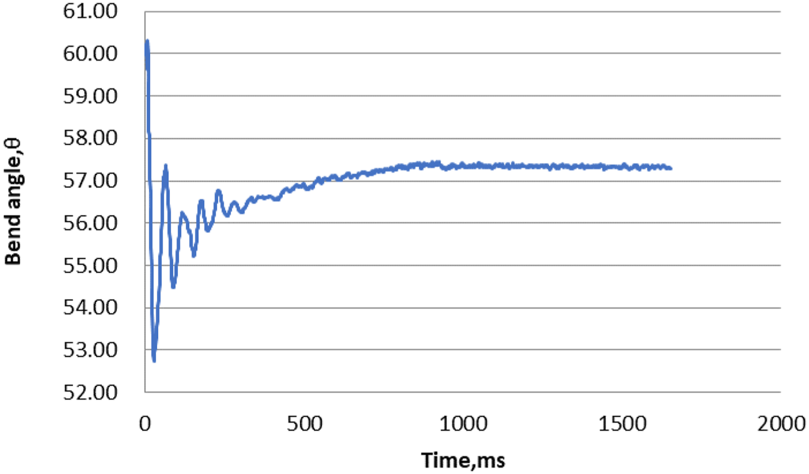
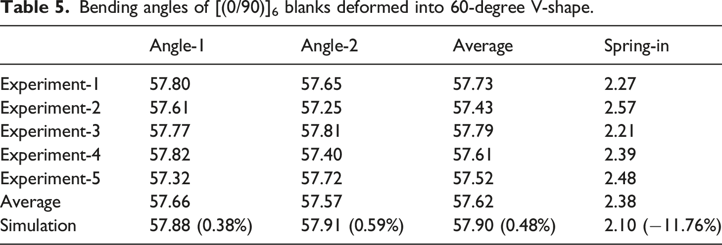
Bending angles of [(0/90)]6 blanks deformed into 60-degree V-shape.
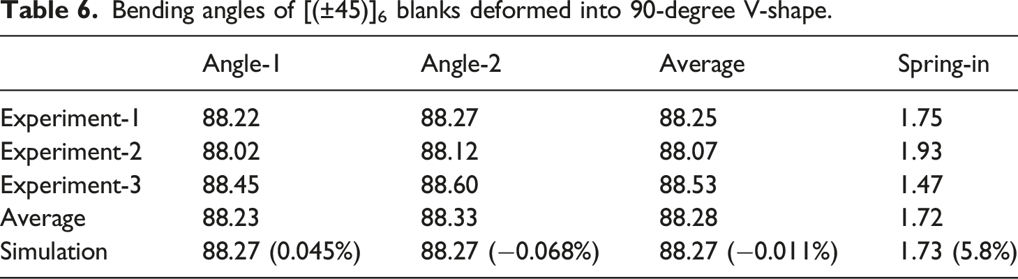
Bending angles of [(±45)]6 blanks deformed into 90-degree V-shape.
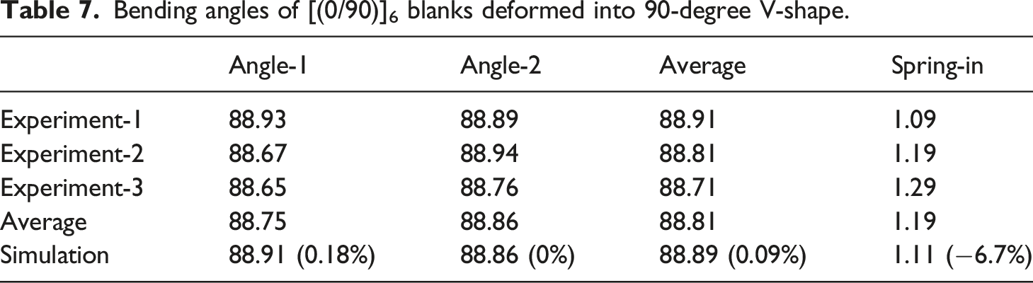
Bending angles of [(0/90)]6 blanks deformed into 90-degree V-shape.
Prediction
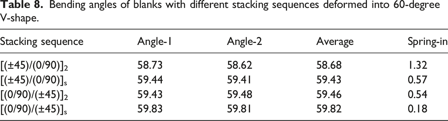
Bending angles of blanks with different stacking sequences deformed into 60-degree V-shape.
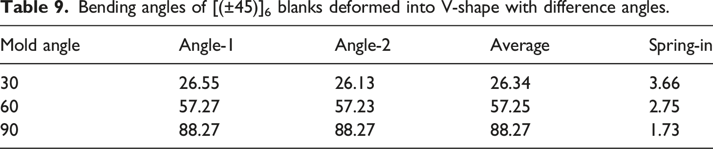
Bending angles of [(±45)]6 blanks deformed into V-shape with difference angles.
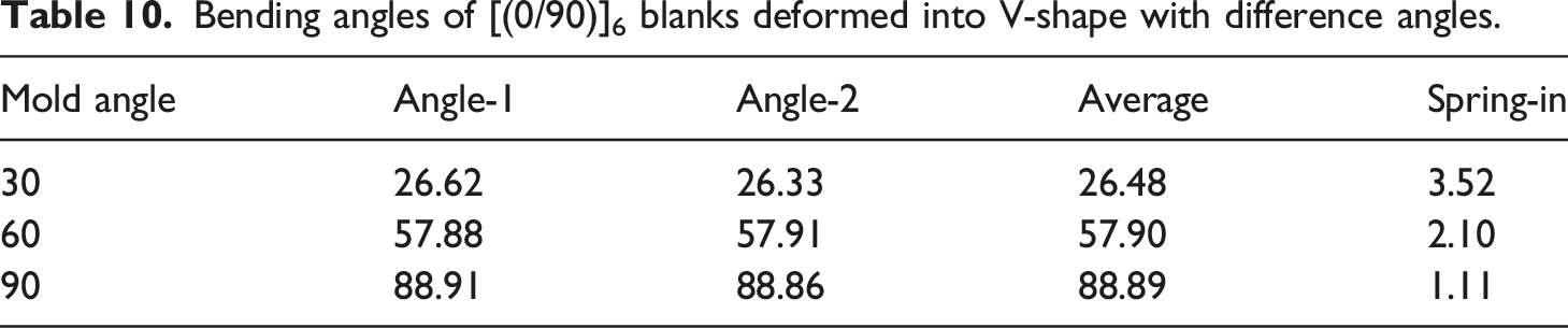
Bending angles of [(0/90)]6 blanks deformed into V-shape with difference angles.
Conclusions
In this work, the woven carbon fiber/polycarbonate thermoplastic composite laminates are thermoformed into V-shaped structures, and then their spring-back or spring-in behavior after demolding is focused. Two types of blanks, [(±45)]6 and [(0/90)]6, are considered and the bending angle of the V-shaped structure may be 60 degrees or 90 degrees. In addition, a finite element analysis including the discrete approach for the woven carbon fabric and a regular resin model is used to predict the spring-in behavior of the composite. From the obtained results, both the experiment and the simulation confirm the spring-in behavior of this thermoplastic composite. As comparing [(±45)]6 and [(0/90)]6 blanks, the spring-in angle is reduced from around 2.60° to 2.38° for a 60-degree V-shape and around 1.72° to 1.19° for a 90-degree V-shape. The [(±45)]6 blank always has a slightly higher spring-in angle than the [(0/90)]6 blank, even though the difference is small. The finite element results show 6% to 12% differences with the experimental values if the spring-in angle is used. If the bending angle is compared, the error is less than 0.6%. One may conclude that the simulation has a nice agreement with the experiment. By using the present finite element analysis, the prediction indicates that the stacking sequence could have an effect on the spring-in angle, and symmetric laminates have less spring-in effect as compared to their unsymmetric counterparts.
Footnotes
Declaration of conflicting interests
The author(s) declared no potential conflicts of interest with respect to the research, authorship, and/or publication of this article.
Funding
The author(s) disclosed receipt of the following financial support for the research, authorship, and/or publication of this article: The financial support from the Ministry of Science and Technology, Taiwan through grant number MOST 108-2221-E-224-032-MY3 is acknowledged.