
Abstract
Manufacturing of thermoplastic composite based on textile preforms made from hybrid yarns is well suited for the production of fiber-reinforced plastic (FRP) in medium- and large-scale production runs. Especially, the consolidation of thermoplastic FRP is currently complicated by the high viscosity of molten material. Woven multilayered and z-reinforced NCF-preforms are very interesting for FRP supposed to withstand three-dimensional loading and impact stress. These preforms with z-directional reinforcement improve the FRP delamination behavior and out-of-plane characteristics. The well-known composite parameters are essential to ensure the use of these materials in a wide range of applications.
Introduction
Modern demands for carbon dioxide reduction are the most strongly affecting developments in mechanical engineering and vehicle construction. These particular industries have the highest energy requirements. Therefore, it is highly effective and necessary to reduce their energy input. By implementing energy efficiency measures, the industry can react to rising energy prices, thus minimizing manufacturing costs and fulfilling existing environmental regulations. Thereby, the continued cost-efficient manufacture of capital and consumer goods in Europe, and especially in Germany, as well as secure jobs can be ensured.
Mass reduction in mobile parts in vehicle construction and mechanical engineering results in reduced energy consumption as well as in increased maximum speed. In vehicle construction, for instance, the standards are tried to be met by using lightweight materials and alternative drive systems. This can only be attained by a sustainable concept, based on interdisciplinary approaches. At today’s state of the art, reliable alternative drives are significantly heavier than conventional drive systems. Thus, the use of alternative drives, presupposing unchanged mass of the other components, would actually increase the energy consumption of vehicle, counteracting the original aim. Therefore, the structure has to be made significantly lighter in order to reduce the total vehicle mass, which can only be achieved by implementing a systematic lightweight construction, 1 which has recently seen increasing use within the automobile industry, caused in part by the suitability of lightweight materials to meet the requirements of safety and comfort measures, which would usually cause a gain in vehicle mass.
In vehicle construction and engineering, mass reduction in moving parts reduces the energy consumption and boosts the maximum cycle times of the machines . 2 The mass of the moving parts thus plays a key role in meeting the existing ecological and economical demands.
In order to manufacture thick-walled components meeting the requirements and exhibiting a high load-bearing capacity, fiber-reinforced composites (FRCs) are conventionally constructed from several layers, which are usually done manually and therefore entail reduced repeatability and substantial expenditure of time. Individual layers of FRCs produced in this manner show a tendency toward delamination under occurring loads. In order to avoid such failure behavior, an additional connection of individual layers with reinforcement threads is necessary. Textile preforms, already manufactured as multilayered woven fabrics with additional z-directional connection threads, are one possibility.
Particularly, thermoplastic fiber-reinforced plastics (FRPs) have successfully found new fields of application during the last years. A crucial advantage over composites with a thermosetting matrix resides in the base materials’ attainable short processing times of components. Thermoplastic components can be affordably produced using highly productive methods (injection molding, thermoforming and hot pressing). Further advantages are in the thermal ductility, the possibility of unlimited remacerating and reforming, the better impact resistance and damage tolerance properties as well as an increased repair-friendliness. To fulfill higher material requirements, the thermoplastic matrix is reinforced with textile preforms made from high-performance woven fabrics. The manufacture of thermoplastic composite based on textile preforms made from hybrid yarns is well suited for the production of FRC in medium- and large-scale production runs. Especially, the creation of thermoplastic FRC is currently complicated by the high viscosity of molten material. A swift and complete impregnation of the reinforcement filaments is therefore possible only with considerable effort, which necessitates a minimization of the flow path of molten thermoplastic.
One long-pursued approach is the use of textile preforms made from hybrid yarns. 3 –7 As the utilized hybrid yarns already consist of the reinforcement and the matrix components, the fiber volume content of matrix and reinforcement component required for each individual construction part can be preadjusted with the hybrid yarn. Furthermore, hybrid yarns, similar to other high-performance filament yarns, can be processed on textile machines. This means that relevant textile structures can be produced in diversity comparable to that of conventional reinforcement preforms.
Textile preforms made of continuous fibers can be adjusted to various, possibly, layered load cases. Thus, it is possible to create complex-shaped FRC in a single, integral surface formation step.
Using hybrid yarn-based thermoplastic matrix materials, the manufacturing of lightweight and complexly formed, high-productivity and high-quality composites becomes possible. 8 To ensure the demanded short cycle times, while simultaneously guaranteeing highly specific properties of structure components, the most suitable method is hot pressing, using continuous fiber-reinforced, near-net-shape thermoplastic preforms. Conventionally, the composition of FRC is performed by stacking several thin-reinforcement preform layers, which is time intensive and costly and obstructs the application of this advanced technology.
Multilayered textile preforms, in comparison, are suited for the reinforcement of higher gauge FRPs due to their use of thicker and preferably denser (=more compact) fabrics, as their multilayeredness facilitates the minimization of the usual stacking of multiple individual reinforcement layers. 9
The z-connection within the multilayered fabric leads to a substantially improved delamination behavior as well as to an increased damage tolerance toward crash and impact. The result is a new preform, suited for large-area and bowl-shaped FRCs, making it ideal for use in vehicle construction and mechanical engineering. A special task is the attainment of a favorable draping behavior, as draping in particular allows for the reshaping of planar preforms and the manufacturing of practice-oriented single- or double-bent FRC components.
Studies have shown that textile structures with an additional z-directional reinforcement exhibit an increased resistance to delamination and impact strains, compared to conventional stacked fabrics. 10 –12
By making a qualified choice in binding yarn material aligned in thickness direction, the delamination and impact behavior can be adjusted adequately. 9 The area weight, depending on yarn material and number of layers, can be set in a wide range. Thus, the stacking of thin-reinforcement preforms into the tool as well as the manufacturing costs can be reduced.
Using multilayered textile preforms made from thermoplastic-based hybrid yarns, a highly productive manufacturing chain can be established. The manufactured FRPs can be formed with various profiles of properties, individually according to the state of fiber reinforcement and matrix material.
Experimental
Hybrid yarns
Several methods for the manufacture of hybrid yarns have been established in the market. During production, filaments as well as staple fibers can be processed into various yarn constructions. This article is based on a special ITM/TU Dresden in-house-produced commingling hybrid yarn manufactured by air jet texturing, which was used for the structural tests and property determination.
The advantages of these yarns are their homogenous mixing of the used continuous filaments as well as their great yarn compaction, which enables further textile technological processing. Commercially available yarn materials can be used in widely varying forms, and the individual component percentages can be adjusted to preference on an extensive range.
By setting the number of forward yarns, the ratio of the components can be adjusted. The commingling yarns are manufactured on a modified air jet texturing machine RMT-D (Stähle GmbH, Reutlingen, Germany). The reinforcement and matrix filament yarns are introduced over separate feed units of an air mixing nozzle, type LD 5.05 (TEMCO oerlikon, Pfäffikon, Switzerland). Due to this working principle, the structure of the commingling yarns does not exhibit a completely parallel alignment of the reinforcement and matrix components in relation to the yarn axis. 13
The developed and manufactured commingling hybrid yarns from glass fibers (GFs; 300 tex E-glass) and polypropylene (PP; 4 × 32 tex) have a reinforcement fiber count of 73 mass%, which corresponds to 52 vol% in the later composites. The linear mass density amounts to 410 tex.
Fabric development
The provided hybrid yarns have an experimentally determined substance diameter of approximately 1 mm. Thus, to result in a cohesive yarn layer, a maximum of 100 yarns per decimeter can theoretically be integrated into the fabric of each reinforcement layer.
It has to be taken into consideration that in three-dimensional (3D) structures, the yarns not oriented in the direction of stress can only contribute partially to load transfer. In turn, the isotropy of the fabrics increases.
The attainable maximum breaking strength of unidirectional composites is highly direction dependent as Böhm et al. figured out. 14
Significantly higher stresses can be conveyed in yarn direction than transversely to it. Böhm was able to prove the relationship between the achievable breaking strength and the angle of stress and yarn directions of the used hybrid yarns. A deviation in the stress direction from the yarn longitudinal axis causes significant losses in tensile strength. An angle of displacement between load directions a thread axis of approximately 8° causes approximately 50% of maximum breaking strength.
For further thermopressing process, the following different fabrics made of GF/PP hybrid yarn were taken into consideration. Unidirectional windings (1D-UDW), Conventional twill weaves (two-dimensional (2D)-TWILL; Figure 1(a)), 2D-reinforced noncrimp fabric (NCF) with an additional binding yarn system (2D-NCF; Figure 1(b)), 3D-reinforced NCF interlocked, cross-linked (3D-NCF-XV; Figure 1(c)) and through the thickness (3D-NCF-XD; Figure 1(d)).
Preliminary tests have also shown that a change in yarn material (e.g. 1200 tex instead of 410 tex) can enable the production of considerably heavier fabric (about 6 kg/m2) with more than 20 yarn layers.
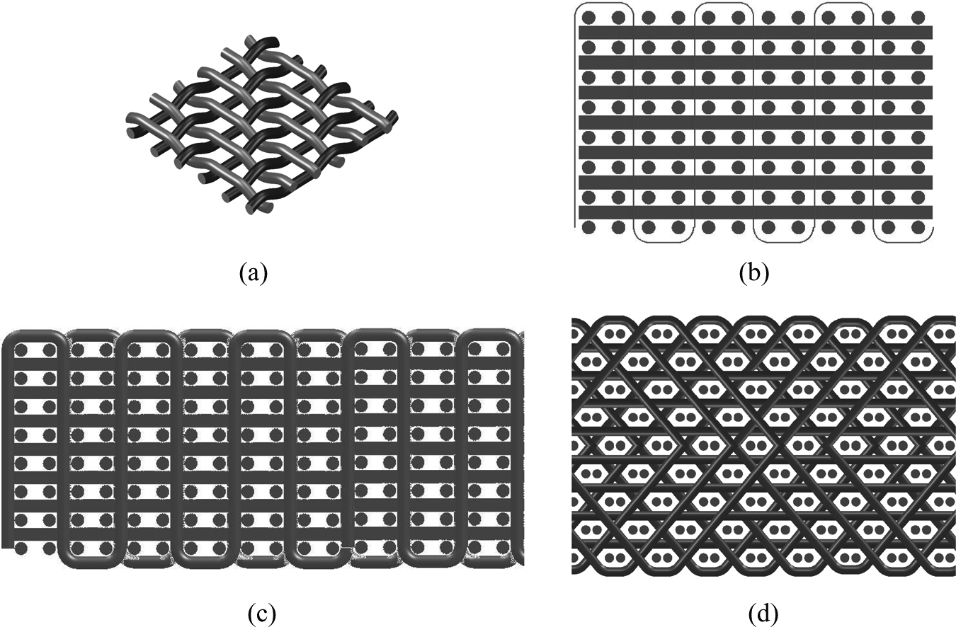
Schematic view of realized structures. 2D-TWILL (a), 2D-NCF (b), 2D-NCF-XV (c) and 3D-NCF-XD (d). NCF: noncrimp fabric; 2D-NCF: 2D-reinforced noncrimp fabric; 2D-NCF-XV: 2D-reinforced NCF cross-linked; 3D-NCF-XD: 3D-reinforced NCF through-the-thickness; 2D-TWILL: conventional twill weaves.
Composite formation
All structures are handled similarly by introducing them into a plate-type, two-part steel tool and taken into the thermopress process.
All the laminates are manufactured by the thermopress process with a Collin p300 PV (Dr. Collin GmbH, Ebersberg, Germany) laboratory press. This equipment allows for thermal crimping of hybrid yarn-based textile structures with thermoplastic components in hot pressing.
Experience from previous research project allows the deduction in an optimum pressing cycle for the manufacture of thermoplastic hybrid yarn laminates.
13
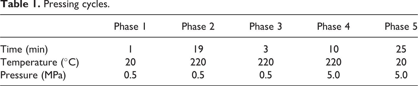
The pressing process runs in five program-controlled phases (Table 1). During the first phase (preheating), the press is preheated to the desired initial temperature. In the second phase (heating up), the press is warmed-up to the required maximum temperature. The third phase serves to thoroughly warm the pressing instrument. During the fourth phase, the actual pressing process takes place under an increase in the applied pressure. To minimize fiber damage, the pressure is applied only after attaining the molten state by the matrix. The fifth and final phase is used to cool the laminate. The cooling rate enables the influence of the degree of crystallinity of the composite, which turns out lower the faster the pressing machinery is cooled.
3,15
Low degrees of crystallinity cause a decrease in the tensile strength and dimensional stability at high temperatures. In order to avoid the growth of air locks in thickness direction and ensure dimensional accuracy, the applied pressure is maintained during the cooling phase.
The specimens are cut to size with a water-cooled, diamond-coated blade circular saw. The sample geometry is selected according to the individual test standard. As the focus is on the influence of multilayeredness, the composites are manufactured from a single-reinforcement preform layer that causes differences between the resulting composite thickness and the standardized thickness.
Pressing cycles.
Results
Test setup
To establish the properties and property degradation during the manufacturing process, samples are extracted and characterized at all production steps.
The thickness of fabrics as well as of composites was determined according to the standard DIN 53855.
The tensile properties were determined by a Zwick-I Smart Pro Z100 (Zwick GmbH & Co. KG, Ulm, Germany) adapted to the individual test standards.
Fiber mass content was detected in 1-h incineration at 625°C, in accordance with the standard DINEN ISO 1172 (method A): representative sample sections are stored in a muffle furnace (Nabertherm-Controller B 170, Naberterm GmbH, Lilienthal, Germany) until reaching constant mass. The thermoplastic components are completely disintegrated. The mass ratios before and after incineration allow for the calculation of fiber mass content of GFs within the yarn.
Fabrics
The realized fabrics were characterized. Here, the draping and load-elongation properties are of special interest. To determine drapeability, the handling, the path-dependent flexural force progression and the shearing behavior are of interest. In this article, only handling and path-dependent flexural force progressions will be examined more closely. For a qualitative assessment of drapeability, the bending was recorded by employing the test procedure BSQ02 (servo motor—driven twist and recording of resulting bending moments). The selected testing assembly largely avoids gravitational influence on the bending force progressions. It becomes apparent that 2D-NCF structures have a higher level of bending force progressions than 3D-NCF structures. Particularly, in weft direction, the path-dependent flexural force increases proportionally to the addition of layers (and thus, an increase in weft density). As stated in the quantitative assessment, it also becomes clear that 3D-NCF-XV structures reach higher bending progressions than 3D-NCF-XD-9, rendering them less drapeable.
The weft yarns of all structures are virtually stretched incorporated into the fabric. There is higher incorporation in warp direction, although it is generally 1° lower than in 2D-TWILL fabric.
For detailed information about textile results see Kleicke’s study. 16
Composite
Because the developed multilayered fabrics are supposed to be used in reinforced thermoplastic composites, the establishment of composite parameters is a crucial criterion for the assessment of their quality. Initially, the fiber mass content of the composites is determined. For all 3D-NCF structures, this content amounts between 72.2 and 72.8% by mass, paralleling 51.1% by volume. The reduction in fiber mass content in comparison to the used source material is mainly caused by the damage loss of thread substance during the weaving process. Die 2D-NCF structures show a fiber mass content of 71.8–72.5%, with difference to the source material explicable by a substance loss and an additional binding yarn (made from matrix material).
The yarns within 1D-UDW are almost elongated located because of the clamping and the lack of z-oriented yarns, as already published. 17 The results show the influence of the binding thread on the fiber mass content in 2D-NCF to be negligible.
Figure 4 shows the fabric cross section of an embedded 2D-NCF-9 fabricin weft direction. The nonundulatedly stacked-reinforcement yarn layers as well as the lanes formed by the binding warp system can be seen clearly.
During composite formation, the fabrics are compressed to approximately 45% of their initial thickness (Table 2). During the process, the molten PP is pressed between the glass filaments, while simultaneously a large portion of the air within the fabric is removed by the pressure. The remaining air causes a slight residual porosity of the composites, visible as black hue in Figure 2.
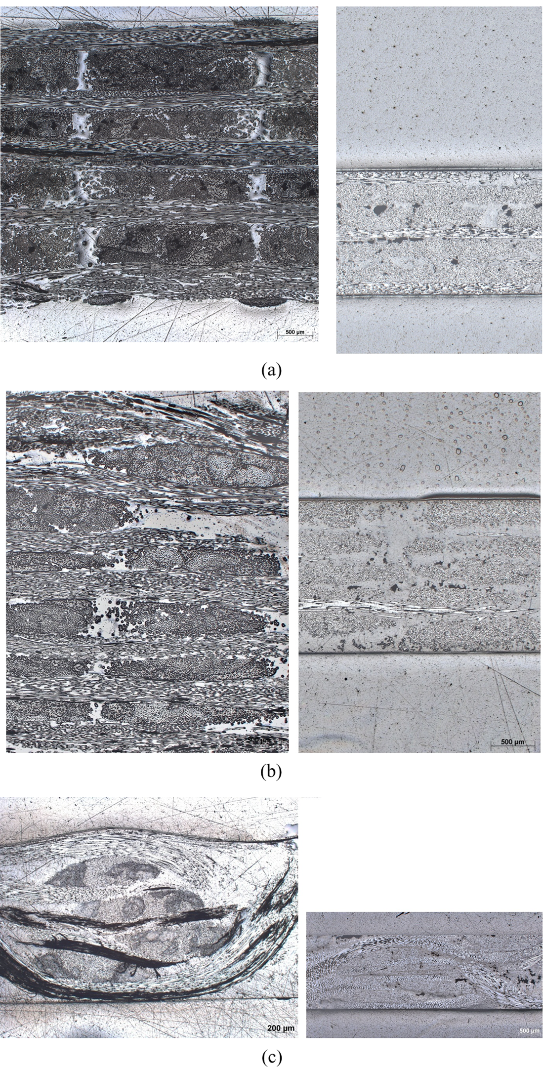
Exemplary microsections of fabric (left) and composites (right). 2D-NCF-9 (a), 2D-NCF-17 (b), 3D-NCF-XV-9 (c), 3D-NCF-XD-9 (d) and 3D-NCF-XD-11 (e). NCF: noncrimp fabric; 2D-NCF: 2D-reinforced noncrimp fabric; 3D-NCF-XV: 3D-reinforced NCF cross-linked; 3D-NCF-XD: 3D-reinforced NCF through-the-thickness.
Compression of different fabrics after thermoforming.
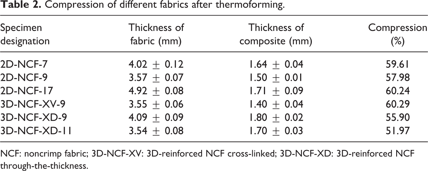
NCF: noncrimp fabric; 3D-NCF-XV: 3D-reinforced NCF cross-linked; 3D-NCF-XD: 3D-reinforced NCF through-the-thickness.
Especially in the 3D structures, the compression has far-reaching consequences for the alignment of binding warp yarns in thickness direction.
During the compression of the hot pressing process, the angle of binding warp threads within the fabric is reduced from 42° to approximately 25° within the composite. This result is representative.
For the detection of traction-tensile modulus, an external linear position measurement using a fine strain extensometer was undertaken. The final elongation of the specimen is determined by optical sampling. The tensile strength and the tensile modulus were tested on both the FRC and the unidirectional-reinforced composites, first in fiber direction (x-direction) and then transversely to it (y-direction). An analysis of the test results for 1D-UDW composites in y-direction is redundant, as the fibers are not oriented in tension direction and accordingly exhibit extremely low values. The 1D-UDW composites have a failure stress of 765 MPa and a final elongation of 1.5% in x-direction. These results are the starting value for normalization.
Generally, lower level of breaking strength parameters of FRCs is founded in only a fraction of the yarns being aligned in load direction while the remainder deviates, which increases the cross-sectional surface but does not contribute to load distribution (Table 3).
Breaking strength parameters for the composite in warp direction (selection).
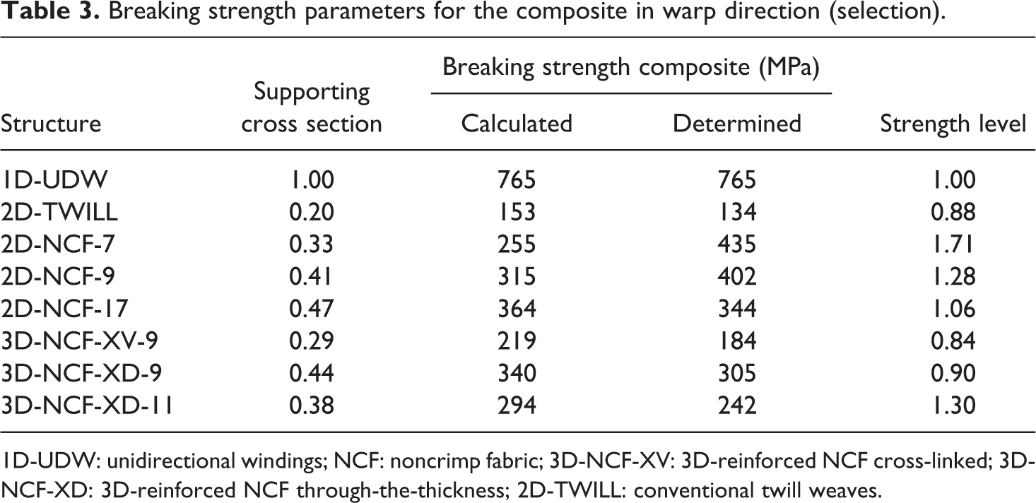
1D-UDW: unidirectional windings; NCF: noncrimp fabric; 3D-NCF-XV: 3D-reinforced NCF cross-linked; 3D-NCF-XD: 3D-reinforced NCF through-the-thickness; 2D-TWILL: conventional twill weaves.
To assess the composite quality, it is sensible to reduce the stress on the load-carrying cross section.
The established tensile strength parameters are overlaid by effects described within the frame of plate theory. 4 ,8,14 As these can be assumed to be equal for all structures, the parameters can be compared quantitatively, at the least. It becomes apparent that yarn undulations, which are particularly common for 3D-NCFs, cause impaired tensile strength parameters.
To establish the bending stiffness characteristics, four-point bending test was performed in accordance with DIN EN ISO 14125:2011, as it offers a constant bending moment between the compression clamps. The required specimens were given class III treatment, that is, their size was 60 × 15 mm2 × composite thickness. For better comparability, the properties were again normalized to the properties of 1D-UDW (Table 4).
Comparison of bending strength properties.
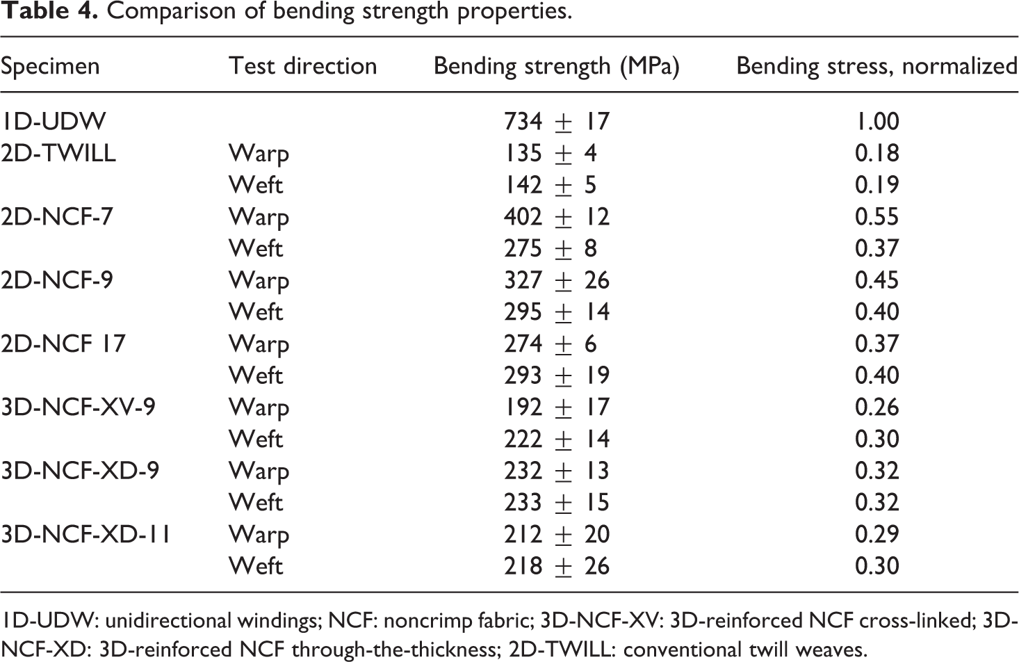
1D-UDW: unidirectional windings; NCF: noncrimp fabric; 3D-NCF-XV: 3D-reinforced NCF cross-linked; 3D-NCF-XD: 3D-reinforced NCF through-the-thickness; 2D-TWILL: conventional twill weaves.
It becomes clear that due to the textile technological linkage of their individual layers by reinforcement threads, 3D-NCFs have a more balanced property relation in warp and weft directions. Once more, conventional 2D-TWILL fabrics scored lowest. As described above, an increase in the layer number brings about a higher warp yarn density per layer due to the selected weaving machine configuration. Thus, 2D-NCF-17 structures, in particular, exhibit a balanced warp/weft ratio. This is mirrored by the bending test properties.
The somewhat reduced properties of the 2D-NCF-9 fabric in comparison with the 2D-NCF-7 fabric can be traced by the reduced thread count of the individual layers in the fabric, as both negatively influence the bending strength. Because of the noncontinuous load-direction binding threads in their outer layers (which are the main load-carrying zone), the 3D-NCF structures feature only reduced bending strength. The conventional fabrics show the lowest results.
The determination of impact energy was performed in accordance with DIN EN ISO 179. For this purpose, the specimens are mounted vertically at a support span of 30 mm, before being exposed to a pendulum impact on their broadside, with the pendulum carrying energy of 15 J.
Table 5 compares the determined properties. Once again it is made clear that the production inherently reduced the thread density of the individual layers of 2D-NCF-9 fabric, which negatively impact the attained properties when compared with the 2D-NCF-7 composites. As described, the 3D-NCF composites exhibit significantly reduced properties due to their structure attributably lower number of stretched–laid yarns. The failure patterns of the variants differ in terms of the break patterns: although 2D-NCF composites are completely severed and show purely brittle-type fracture, the 3D-NCF specimens are not severed. The binding warp prevents a thorough failure. Here, as expected, the positive effect of the binding warp comes into play—predestining them for safety-sensitive uses in which the prevention of delamination is the key.
Comparison of impact strength properties.
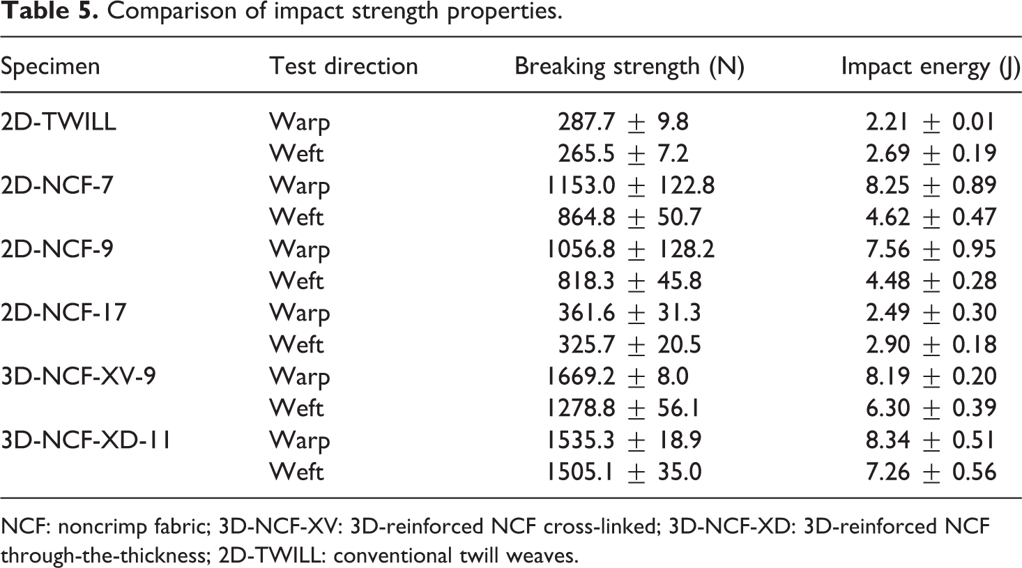
NCF: noncrimp fabric; 3D-NCF-XV: 3D-reinforced NCF cross-linked; 3D-NCF-XD: 3D-reinforced NCF through-the-thickness; 2D-TWILL: conventional twill weaves.
The torsional stiffness test was performed according to the edge-crack-torsion (ECT) method, used primarily in aerospace technology and specified in the NASATM-2004-213269 Norm. 15,18 The load frame for ECT tests uses a symmetrical two-point test device in which two diagonally aligned support points hold the specimen corners, two each topside and bottom side. The load-path diagram is then recorded with the position sensor and the load measuring cells of the testing device and translated into a load-angle diagram (Figure 3). Three load cycles are performed in which the lower final value of the hysteresis is approached power controlled, whereas the higher final value is approached path controlled.
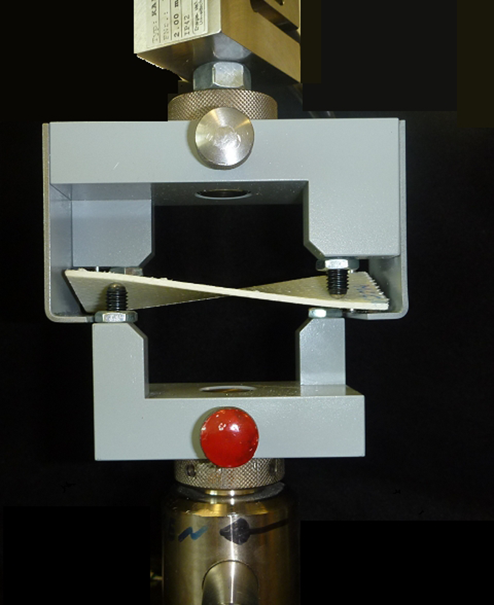
Test configuration ECT, according to Norm. ECT: edge-crack-torsion.
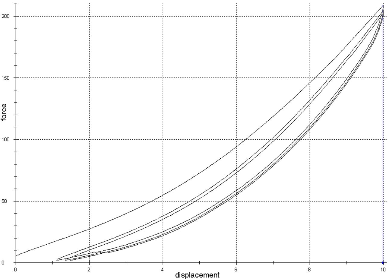
Exemplary hysteresis course of a 3D-NCF-XD-9 laminate. NCF: noncrimp fabric; 3D-NCF-XD: 3D-reinforced NCF through-the-thickness.
Preliminary tests have not shown the ductility of the thermoplastic matrix to cause crack formation on notched specimens. Therefore, to describe the influence of binding threads on composite properties of a fabric layer, unnotched specimens were used. Deviating from the normatively described horizontally notched specimens, unnotched ones are utilized. The modified specimen structure is allowed for the detection of their clean torsion parameters. Figure 4 exemplarily depicts the course of a load-path characteristic. The course exhibits a distinct hysteresis behavior. Particularly, the high amount of residual deformation is representative of all laminates.
Table 6 compares the energy absorption capacity of various laminates and the maximum force for specimens twisted at 36°. The energy absorption capacity under torsion strain is nearly in the same level for all composites. Solely, the inconsistencies of 3D-NCF-XV-9 composites, caused by the abrupt, binding-inherent warp changing, give them considerably lower values. Although the 3D-NCF-XD composites contain far fewer stretched-aligned threads than 2D-NCF composites, their properties are on the same level. This is an essential indication of the positive influence of binding warp threads on composite properties.
Bending force of the examined laminates (at 36° torsion).
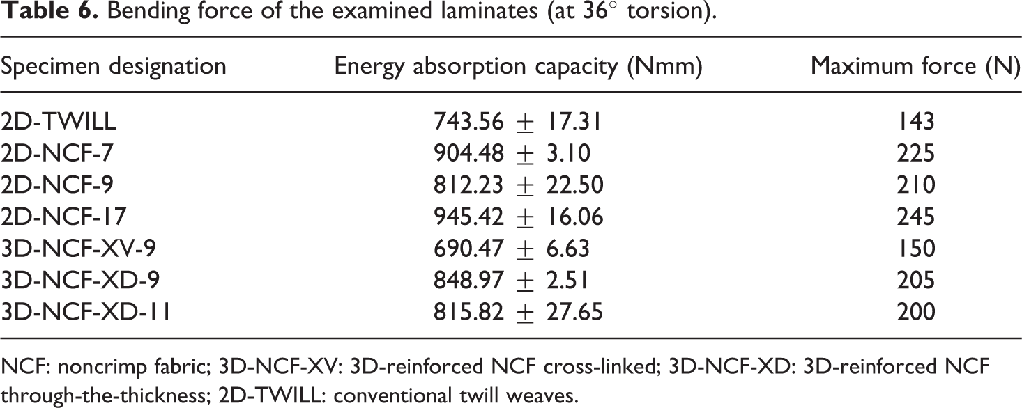
NCF: noncrimp fabric; 3D-NCF-XV: 3D-reinforced NCF cross-linked; 3D-NCF-XD: 3D-reinforced NCF through-the-thickness; 2D-TWILL: conventional twill weaves.
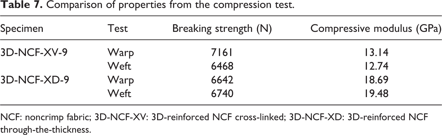
The pressure test is performed according to DIN EN ISO 14126:2000 on selected laminates. To compare the influence of the binding warp configuration, 3D-NCF-XD-9 and 3D-NCF-XV-9 laminates were selected and confronted in Table 7. As 3D-NCF-XV-9 has a production-related lower weft density, they expectably display a lower breaking force under pressure strain in warp direction and a higher breaking strength in warp direction. Since the undulation of reinforcement warps is slightly elevated, the tensile modulus is reduced.
Comparison of properties from the compression test.
NCF: noncrimp fabric; 3D-NCF-XV: 3D-reinforced NCF cross-linked; 3D-NCF-XD: 3D-reinforced NCF through-the-thickness.
For a final assessment of delamination strength, two laminates are chosen according to laboratory capacities. One 2D and one 3D composites with quite similar architecture are taken into consideration, resulting from the static tests:
2D-NCF-9: which act more or less than a composite, made from stacked layers,
3D-NCF-XD-9: as a representative 3D composite with additional z-reinforcement.
Impacts are among the most frequent damages to FRP structure components, especially within aeronautics. Although it usually does not leave visible superficial damage, it can cause delamination of individual layers within the structure. During operation under dynamically alternating loads, these delaminations can grown and lead to an increasing structural degradation. This leads to component failure. Initially, the impact energy to attain the desired impact depth of 1 mm was established at 54 J and used for further tests. The samples (100 × 150 mm2) were clamped on three sides. Strain gauges (four each side) were fixed on the specimen. The impactor with a diameter of 10 mm hit the specimen horizontal with 54 J. After the impact tests, the examined laminates were ultrasonically scanned in an immersion bath in order to establish the damage distribution. The pictures in Figure 5 show the externally visible damage areas as well as the damage areas detected in the ultrasonic bath. The pseudocolor image shows the delaminated areas in red, the heavily damaged ones in yellow and the undamaged areas in blue. Areas suffering from preliminary damage are in green. It is obvious that the 2D-NCF-9 fabric is delaminated nearly completely. At the 3D-NCF-XD-9 sample, failure expanse is limited to a small area (red color) in the 3D-NCF structure. A large part of the laminate is undamaged, due to the z-reinforcement. The strong dominance of warp yarns causes preliminary damages to develop primarily in weft direction (visualized by the green vertical line).
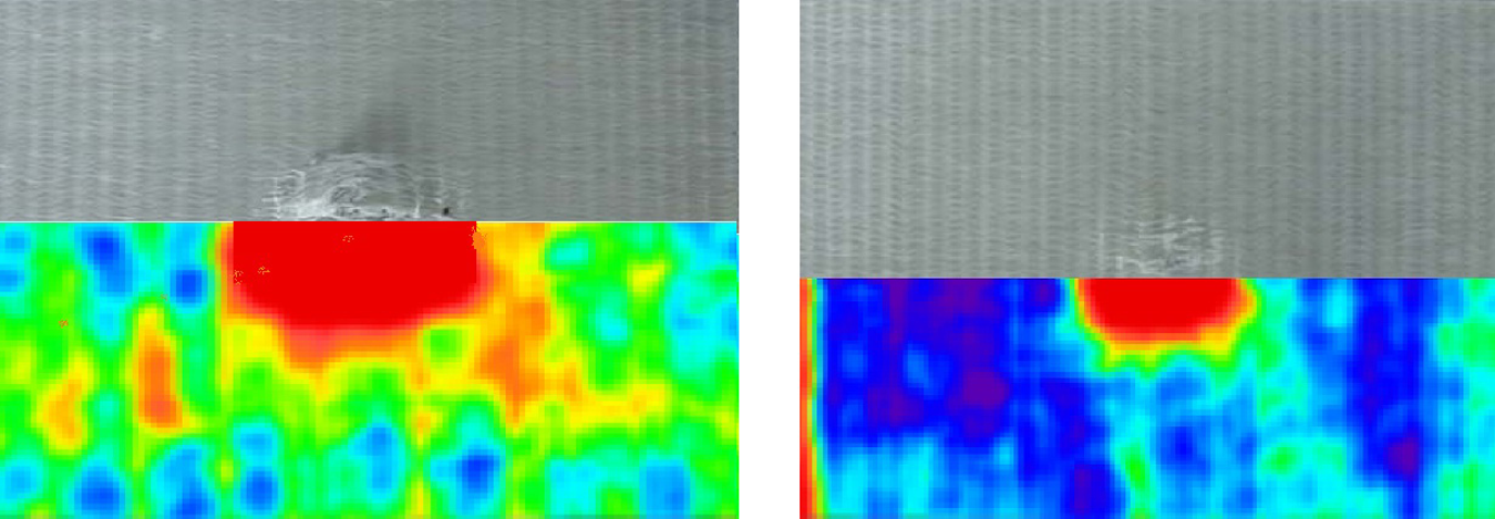
Impact strained structures including pseudocolor ultrasound image—2D-NCF-9 (left) and 3D-NCF-XD-9 (right).
Conclusion
The textile technological tests show that it is basically possible to manufacture compact, hybrid yarn-based multilayered fabrics with high surface mass and reproducible mechanical properties. It is irrelevant whether or not the multilayered fabrics are fitted with an additional z-reinforcement. Purposeful machine modifications allow for the realization of these high-density-multilayered fabrics. The developed NCF structures display nearly stretched-aligned reinforcement threads and stand out to their comparatively good drapeability properties. Thus, the devised fabrics make complexly formed geometries possible, at a highly minimized handling effort.
Using thermoplastic-based hybrid yarns, a uniform impregnation of the reinforcement filaments during composite formation can be achieved. The used hot pressing method allows for a significant reduction in tact time in building component consolidation.
Overall, the produced composites display good mechanical properties. Various structures have proven the necessity of requirement-based textile preform development. For purely tensile load-bearing components, 2D-NCFs are the first choice. For bowl-shaped components, which usually bear torsion and bending loads, fabrics with an additional z-reinforcement should be used. Here, it is advisable to use interlock fabrics with incremental binding warp offset (3D-NCF-XD). Further developments have to be made in the optimization of the z-reinforcement proportion.
In comparison with conventional FRCs used to date, the composites made from multilayered NCFs display much better mechanical properties. The load-adjusted position of reinforcement yarns makes it possible to fully exploit the fiber substance strength.
Footnotes
Funding
The German Research Foundation (DFG) financially supported the Collaborative Research Centre “Textile-reinforced composite components for function-integrating multi-material design in complex lightweight applications” (SFB 639, TP A3 & D3) at the Technische Universität Dresden, Germany.