
Abstract
The mechanical, thermal, and fracture morphological characterization of low-density polyethylene (LDPE) composites reinforced with vapor-grown carbon nanofibers (VGCNFs) is presented in this article. VGCNF/LDPE composites with different VGCNF weight percentages were prepared by single-screw extrusion followed by injection molding. Scanning electron microscopy showed that VGCNFs were predominantly dispersed uniformly within the LDPE matrix. Differential scanning calorimetry has shown that the VGCNF/LDPE composites crystallized at higher temperatures than pure LDPE polymer. Tensile testing has shown that strength and Young’s modulus of VGCNF/LDPE composites were improved by 15% and 44%, respectively, when the VGCNF loading reached 3 wt%.
Keywords
Introduction
Polymer nanocomposites are used in a broad spectrum of industries. 1 Due to its unique properties, vapor-grown carbon nanofibers (VGCNFs) reinforcements potentially offer substantial improvement in polymer properties such as excellent strength and stiffness, high strength to weight ratio, high thermal stability, and durability. 2,3 Carbon nanofibers (CNFs) provide an extensive array of beneficial properties including enhanced electrical conductivity, mechanical reinforcement, improved heat distortion temperatures, and increased electromagnetic shielding. 4 –6 VGCNFs are also an economical alternative to carbon nanotubes and are more easily manufactured. 7 VGCNFs are produced by catalytic chemical vapor deposition of a hydrocarbon or carbon monoxide over a surface of metal or metal alloy catalyst. 8 Typical VGCNF structures are long hollow filaments comprising a single or double layer of graphitic carbon planes, which stack parallel along the fiber axis. 9 VGCNFs usually have a diameter ranging from 50 nm to 200 nm with a high aspect ratio. 10
Low-density polyethylene (LDPE) is a thermoplastic characterized by low crystallinity and its ability to retain toughness and pliability over a wide temperature range. 11 This weakly crystallized addition polymer is composed of highly branched chains, whose structural characteristics are vitally important to VGCNF dispersion within the polymer matrix. 12,13 The enhancement of polymer properties is dependent on the nanoparticles dispersion and adhesion with polymer matrix. 14,15 Ultimately, the ability to manipulate the alignment and dispersion of VGCNFs within the polymer matrix should result in significant improvements in mechanical, thermal, and electrical properties of the composite. The major challenges surrounding VGCNF employment involve overcoming nanofibers agglomeration to improve dispersion and weak interfacial bonding between nanofibers and matrix. 16 Developing techniques to overcome these issues would result in further enhancement of polymer properties.
In this study, LDPE reinforced by different loadings of VGCNF was investigated. Extrusion and injection molding were utilized to process the composites. The resulting nanocomposites were characterized by durometer hardness, tensile testing, extrusion plastometer analysis, differential scanning calorimetry (DSC), and scanning electron microscopy (SEM).
Experimental procedures
Materials
EM 460 1 is the LDPE used in this study provided by Westlake Polymers Corporation (Houston, TX). The ultimate tensile strength is 13.1 MPa (1900 lbf/in2). The elongation yield is 120%. The Young’s modulus is 234.4 MPa (34,000 lbf/in2). The melt index is 27 g/10 min. Vapor-grown carbon nanofibers, manufactured by Pyrograf Products, Inc. (Cedarville, Ohio), are used as the reinforcing agent in this study. The specific fiber identification is PR-24-XT-LHT. PR-24 has an average diameter of about 100 nm and has a minimal chemical vapor deposited layer of carbon on the surface of the fiber; LHT refers to CNF production by heat treatment with temperatures of 1500°C, which converts chemical vapor-deposited carbon present on the surface of the fiber to a short-range ordered structure. This heat treatment also produces nanofibers with higher electrical conductivity. PR-24-XT-LHT CNFs have an average diameter of 129 nm and a length of 30,000–100,000 nm. The tensile modulus of this nanofiber is 600 GPa on average with a tensile strength of about 7 GPa.
Preparation of VGCNF-reinforced LDPE composites
VGCNFs were dispersed into the LDPE by extrusion using a Killion single-screw extruder. First, LDPE pellets mixed with 0.1, 0.25, 0.5, 0.75, 1, 1.5, 2, 2.5, 3 wt% of VGCNFs were initially blended at room temperature for 40 min using a rotary mixer at 60 r/min. At that time, most of the VGCNF clusters, as received from the vendor, were broken. The VGCNF and the LDPE pellets were fed to the extruder. The screw of the extruder applies the shear force that is necessary to disperse VGCNF in the LDPE. The extruder screw speed was kept constant at 40 r/min and operating temperatures were set at 135°C for the first barrel zone and at 149°C for the 2 remaining adaptor and die zones. Neat (i.e., unreinforced) LDPE was also extruded under the same conditions for comparison purposes. The melt string was immersed in a water bath upon exit of the extruder die. This trapped the nonequilibrium morphology of the composite. The extruded VGCNF/LDPE composite material pellets were then made using a pelletizer attached to the extruder. Extruded pellets with an average diameter of 2.2 mm and average length of 3.0 mm were then obtained.
The extruded VGCNF/LDPE pellets were fed to a Morgan-Press plastic injection molding machine to mold tensile specimens according to American Society for Testing and Materials (ASTM) D638. Molding was performed using barrel and nozzle temperatures of 218°C and a mold temperature of 113°C. The injection pressure was set to 27.6 MPa with a clamp force of 12 tons. To prevent variations in the thermal history of molded specimens, the barrel was loaded with just enough pellets to make one specimen. The barrel was then purged once with neat LDPE pellets after each injection. After loading the barrel, the pellets were melted for 2 min, followed by 27.6 MPa of applied force for 20 s to pack the mold. After releasing the pressure, the specimen was allowed to cool for 2 min and removed from the mold. Temperature, pressure, and time are the main factors that affect specimen performance. Therefore, the barrel was purged and then reloaded postinjection, to ensure that each of the blends and specimens had the same thermal history and residence time in the barrel.
Characterization techniques
Thermal, mechanical, and morphological characterization techniques were used to analyze the molded materials. Tensile properties were determined according to ASTM D638 using an Instron Tensile Tester (Model 3366) on injection-molded dog bone-shaped test specimens. A gauge length of 50 mm and crosshead speed of 50 mm/min were utilized. Specimens had a thickness of 3 mm and a width of 13 mm at the center. All tests were conducted under ambient conditions. The hardness of the specimens was measured using a Model M202 Durometer according to ASTM D2240. A Type D indentor and Type 1 operating stand were used in this test.
Fracture morphological analysis was performed using an SEM. The VGCNF/LDPE composites were observed under JSM 6300 SEM. The SEM images were taken using the same parameters with 15 kV acceleration voltage, 5 spot-size, and 35 s scanning speed. The preparation of specimens used in this study includes rapid cooling method and fracture of polymer. VGCNF/LDPE composites were immersed in liquid nitrogen for 5 min. Frozen materials were simply shattered with a hammer. Small pieces of fractured materials were placed on a specimen stub. Then specimen was coated with 0.6 nm gold which connects the specimen to the stub and eliminates charging for SEM imaging.
Thermal properties of the molded VGCNF reinforced LDPE composites were determined using a DSC. Measurements were carried out in a DSC 131 apparatus produced by SETARAM, Inc (Pleasanton, CA). The samples were cut in the form of thin discs, with weight ranges from 10 mg to 13 mg. Specimens were analyzed over a temperature range from 30°C to 200°C. A heating rate of 10°C/min was used without sweeping gas. The temperature was then held at 200°C for 1200 s. The specimens were then cooled to 30°C at a scanning rate of 10°C/min. The onset temperature, peak temperature of melting and crystallization, and percentage crystallinity of each composite with varying VGCNF weight percentages were determined using a heat of fusion of 280 J/g for fully crystalline polyethylene. 17
Melt flow rate (MFR) is a significant polymer property that can be used to find the average molecular weight of the material. MFR is also an integral part of determination and control of polymer processing. Polymers with high MFR are typically used in injection molding, while lower MFR polymers are used in blow molding. MFR of VGCNF/LDPE composites was measured according to ASTM D1238 by an extrusion plastometer manufactured by Tinius Olsen, Inc (Horsham, PA). The specimens were heated in the barrel with a set temperature of 190°C for 240 s. A load of 2.16 kg was applied to the melt specimens as they were extruded through a standard die with a 2.0 mm diameter and a length of 8.0 mm.
Results and discussion
Mechanical properties
The durometer hardness curve of the VGCNF/LDPE composites with a loading of various VGCNF/LDPE weight percentages displays an overall trend of increased hardness as the VGCNF content increased as shown in Figure 1. Three specimens were tested for every case. The composite material containing 3 wt% of VGCNF displayed an approximate 7.14% increase in hardness, compared to neat LDPE. The increase in durometer hardness values of the polymer nanocomposites as VGCNF content increases was expected due to the directly proportional relationship of the durometer hardness to the elastic modulus of material. This trend was expected since VGCNF modulus is naturally much higher than that of LDPE.
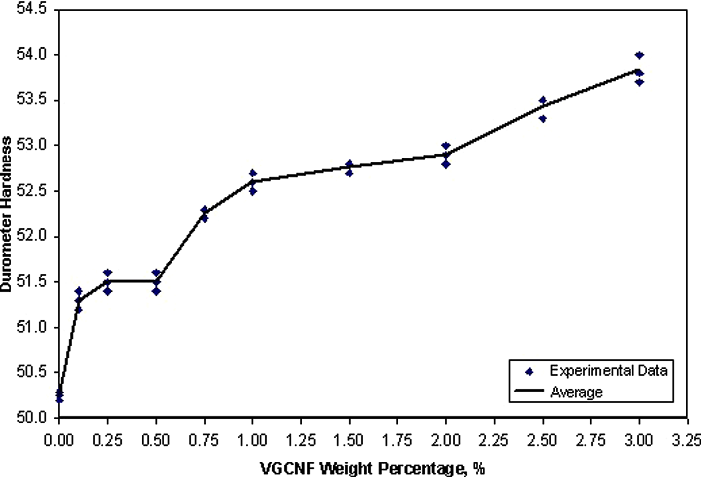
Durometer hardness values versus vapor-grown carbon nanofiber (VGCNF) weight percentage.
The ultimate tensile strength, Young’s modulus, nominal strain, and toughness properties of VGCNF/LDPE composites with various VGCNF weight percentages and neat LDPE are graphically presented in Figures 2, 3, 4, and 5, respectively. Three specimens were tested for every case. The ultimate tensile strength and modulus of the nanocomposites increase with increased VGCNF loading, as shown in Figures 2 and 3. These results are in accordance with the results of hardness test. Both revealed that reinforcing LDPE with VGCNFs can improve polymer strength. Improvements in ultimate tensile strength and modulus for VGCNF/LDPE composites with low VGCNF weight percentage (lower than 1.0 wt%) are less evident. The average Young’s modulus and ultimate tensile strength of the 3 wt% VGCNF/LDPE composites are 44% and 15% higher than neat LDPE, respectively. Figure 4 shows that nominal strain at maximum load exhibits a linear decrease as a function of VGCNF weight percentage, which means that VGCNF reinforcement reduces LDPE ductility while improving strength. As shown in Figure 5, the nearly horizontal toughness trend indicates a very little effect on LDPE toughness, as a result of improved LDPE strength and reduced ductility. The VGCNFs may bridge across the microcracks developed due to loading causing hindrance in the crack growth and consequently increasing the strength of the VGCNF/LDPE composites.
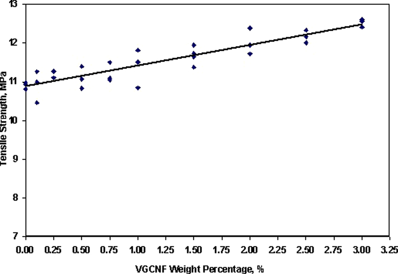
Ultimate tensile strength as a function of vapor-grown carbon nanofiber (VGCNF) loading.
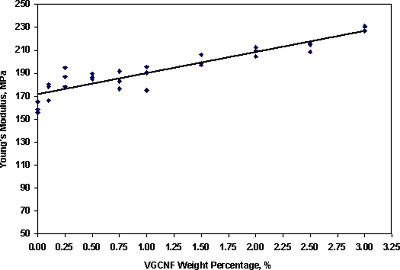
Young’s modulus as a function of vapor-grown carbon nanofiber (VGCNF) loading as determined by tensile testing.
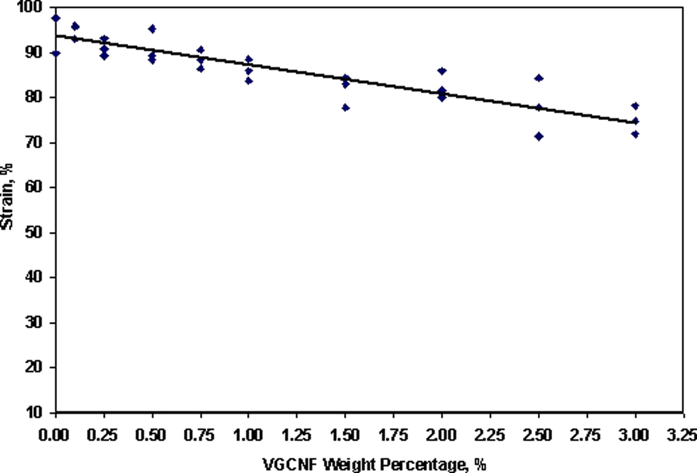
Tensile strain at maximum load as a function of vapor-grown carbon nanofiber (VGCNF) loading.
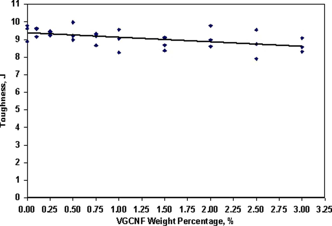
Toughness at maximum load as a function of vapor-grown carbon nanofiber (VGCNF) loading.
Thermal properties
Average DSC results with standard deviations for VGCNF/LDPE composites and neat LDPE from heating zone.
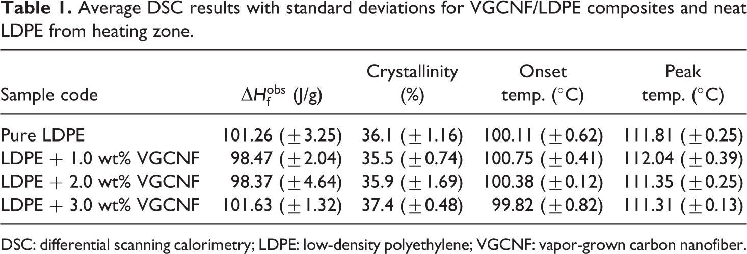
DSC: differential scanning calorimetry; LDPE: low-density polyethylene; VGCNF: vapor-grown carbon nanofiber.
Average DSC results with standard deviations for VGCNF/LDPE composites and neat LDPE from cooling zone.
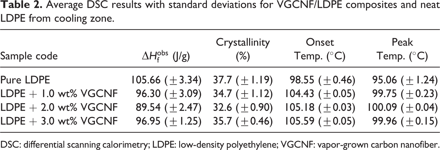
DSC: differential scanning calorimetry; LDPE: low-density polyethylene; VGCNF: vapor-grown carbon nanofiber.

The value of
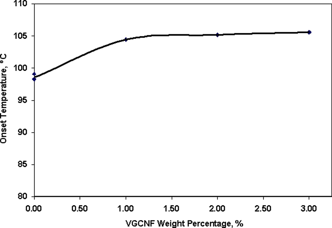
Onset temperatures cooling zone as a function of vapor-grown carbon nanofiber (VGCNF) loading.
Figure 7 shows the MFR of VGCNF/LDPE composites with different percentages of VGCNFs. Three specimens were tested for every case. The MFR of the VGCNF/LDPE composites decreases as the percentage of VGCNFs increases. A sharp decrease can be observed before 1 wt% and after 2 wt%, while a slow decrease of MFR between 1 wt% and 2 wt% was observed.
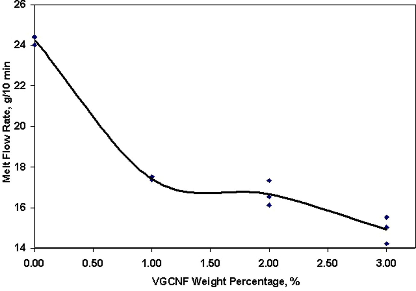
Melt flow rate as a function of vapor-grown carbon nanofiber (VGCNF) loading.
Fracture morphological analysis
The fracture morphology of VGCNF/LDPE composites with various VGCNF weight percentages were characterized by SEM. Figure 8 shows the VGCNFs as provided by the vendor. Relatively large VGCNF agglomerates were observed as a result of entanglement and aggregation between individual nanofibers. Initially, the VGCNFs were mixed with the LDPE. By the shear force applied during the extrusion and injection molding processes, most of these aggregates became well dispersed as individual fibers in the LDPE as shown in Figures 9(a). Figure 9(b) illustrates the SEM image of fracture surface of a specimen of LDPE composite reinforced with 3 wt% of VGCNF. It can be observed from the figure that the VGCNFs are oriented in the direction of the injection inside the mold. Figure 10 also shows a predominantly homogeneous VGCNF distribution through the entire cross-section of the specimen. However, some agglomerates of VGCNFs were observed in other specimens as shown in Figure 10.
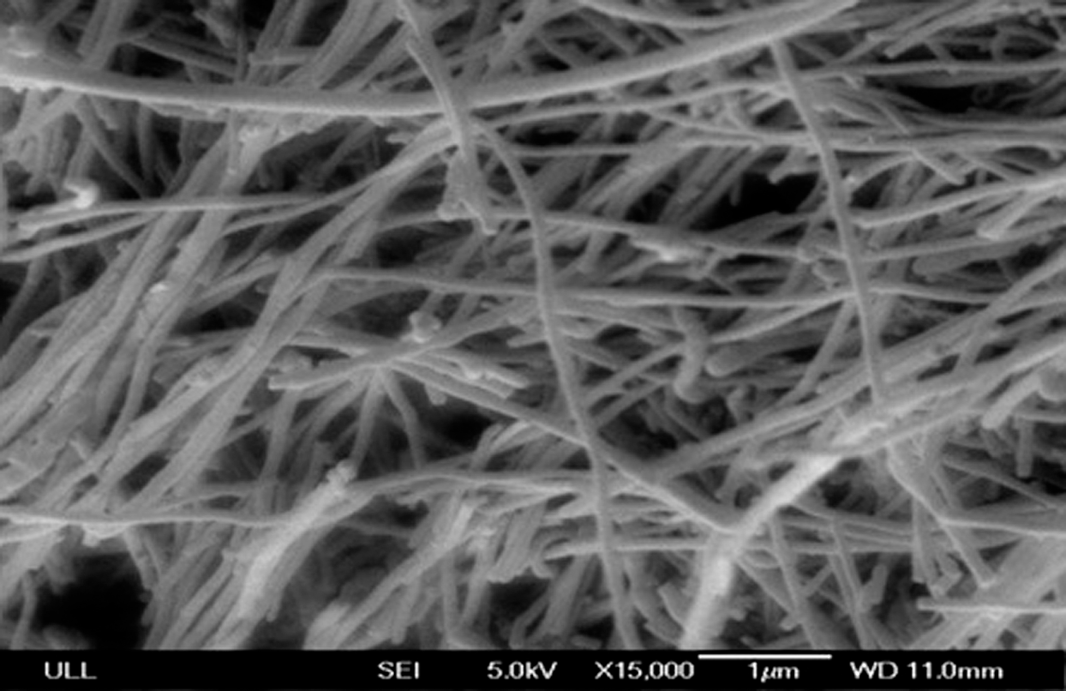
Scanning electron microscopy (SEM) image of neat vapor-grown carbon nanofibers.
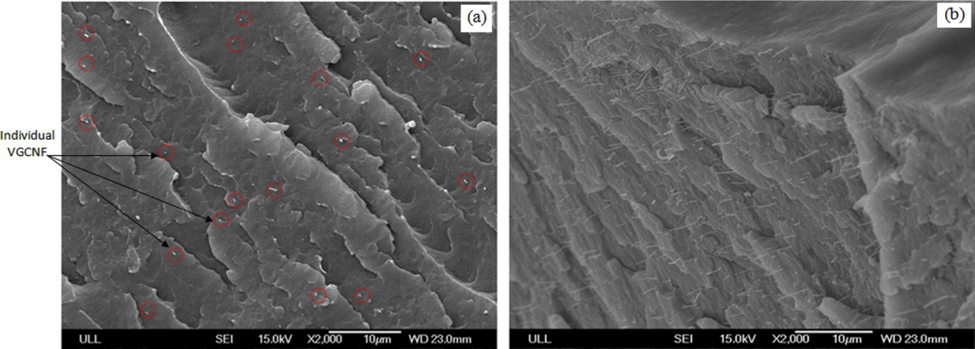
Scanning electron microscopy (SEM) image of (a) VGCNF/LDPE composites with 0.1 wt% VGCNF and (b) cross-section of VGCNF/LDPE composites with 3.0 wt% VGCNF. VGCNF: vapor-grown carbon nanofibers; LDPE: low-density polyethylene.
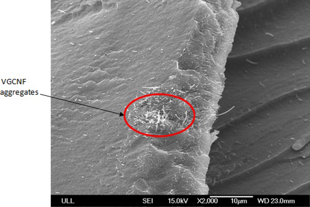
Scanning electron microscopy (SEM) image, cross-section of VGCNF/LDPE composites with 1.0 wt% VGCNF with observed agglomeration. VGCNF: vapor-grown carbon nanofiber; LDPE: low-density polyethylene.
Conclusions
This work characterized the thermal, mechanical, and morphological properties of LDPE composites reinforced by VGCNFs. VGCNFs were dispersed in the LDPE with different loading percentages of 0.1%, 0.25%, 0.5%, 0.75%, 1%, 1.5%, 2%, 2.5%, and 3% weight of LDPE. The investigated VGCNF/LDPE composites were fabricated by extrusion and injection molding. Based on the findings of this study, it was found that low loading amounts of VGCNF dispersed in the LDPE can produce a good network of fibers in the LDPE matrix that help to improve the mechanical properties including resistance to crack propagation. The VGCNF may bridge across the microcracks developed due to loading causing hindrance in the crack growth, and consequently increasing the strength of the VGCNF/LDPE composites.
The composite material containing 3 wt% of VGCNF displayed an approximate 7.14% increase in hardness compared to neat LDPE. The Young’s modulus and ultimate tensile strength of the 3 wt% VGCNF/LDPE composites are 44% and 15% higher than neat LDPE, respectively. The nominal strain at maximum load of VGCNF/LDPE composites exhibits a linear decrease indicating that the VGCNF reinforcement reduces LDPE ductility while improving strength. Improvements in ultimate tensile strength and modulus for VGCNF/LDPE composites with a VGCNF weight percentage lower than 1% are less evident. Adding 3 wt% of VGCNF to LDPE reduces the MFR of the LDPE by 38%. The crystallization onset temperatures of VGCNF/LDPE composites were higher than those of pure LDPE, which means adding VGCNF to LDPE causes the polymer to solidify sooner on cooling. This has the processing advantage of potentially reducing the hold time for a mold during injection operations but has the disadvantage of a reduced amount of time to fill the mold under a given set of processing conditions before solidification occurs. Morphological analysis of the fracture surface of VGCNF/LDPE composites showed that VGCNFs were oriented in the direction of the injection inside the mold with a well-dispersed VGCNF distribution. However, some agglomerates were also observed.
Footnotes
Acknowledgements
The authors would like to thank Ms Rebecca Scherff, Director of the Advanced Materials Laboratory at the Manufacturing Extension Partnership of Louisiana (MEPOL), for her help and support. The authors would like to extend their thanks and appreciation to Dr Thomas Pesacreta, Director of the UL Lafayette Microscopy Center. Special thanks are also extended to the whole research team of the Laboratory for Composites Materials (LCM) at the University of Louisiana at Lafayette, especially, Mr John Prendergast.
Note
Funding
This research received no specific grant from any funding agency in the public, commercial, or not-for-profit sectors.