
Abstract
This article numerically investigated the curing temperature effect on matrix shrinkage crack and the effect of matrix shrinkage cracking on delamination in composite T-piece specimens using a modified interface cohesive model with thermal effects accounted. Thermal relative coefficient was introduced to produce the relative thermal displacement in the formulation of interface cohesive elements. The thermal shrinkage crack in the deltoid region of T-piece was simulated. Effect of this thermal initial cracking on the prediction of dominated delamination [Chen, J., Ravey, E., Hallett, S., Wisnom, M. and Grassi, M. (2009). Prediction of Delamination in Braided Composite T-Piece Specimen, Composites Science and Technology, 69(14): 2363–2367; Chen, J. (2011) Simulation of Multi-directional Crack in Braided Composite T-Piece Specimens Using Cohesive Models, Fatigue & Fracture of Engineering Materials & Structures, 34(2): 123–130.] of T-piece under T-pull loading case was also studied. The investigation indicated that some improper restraints to T-piece specimens during the curing process will induce so called thermal shrinkage cracks in the deltoid region of T-piece. This sort of thermal related matrix shrinkage crack has limited effect on the capacity of T-piece to resist T-pull loading. Radius laminates are the main load carrier in the T-pull loading case. This modeling investigation supplied considerable information for the design and manufacture of T-piece related composite components under pulling condition. Further investigation considering loading cases such as bending and combination with bending and T-pull is suggested in the future work to explore general effects of thermal related matrix shrinkage cracking on delaminating.
Keywords
INTRODUCTION
Study of composite T-piece specimens has received sound attention as it is an important component in aerospace structures and wind turbine blades. Thermal effects from manufacture will remain in components as residual stresses or strains, and possibly incur thermal shrinkage cracking in the matrix. There was evidence of this in manufacturing some T-piece specimens. Investigation of thermal effects on matrix cracking and the effect of thermal related matrix initial crack on delamination mechanisms will benefit the design and manufacture of such composite components. Figure 1 shows a composite T-piece specimen under pull load together with local failure pattern in the area of deltoid of T-piece, which presents a thermal shrinkage crack in matrix, initial delamination point, and dominated delamination. Dominated delamination was recognised at the site between radius laminates and deltoid region by experimental and numerical work reported in [1]. The dominated delamination is actually a main crack growth in the failure pattern of T-piece under a pull load, which associates a significant reduction of structural stiffness.
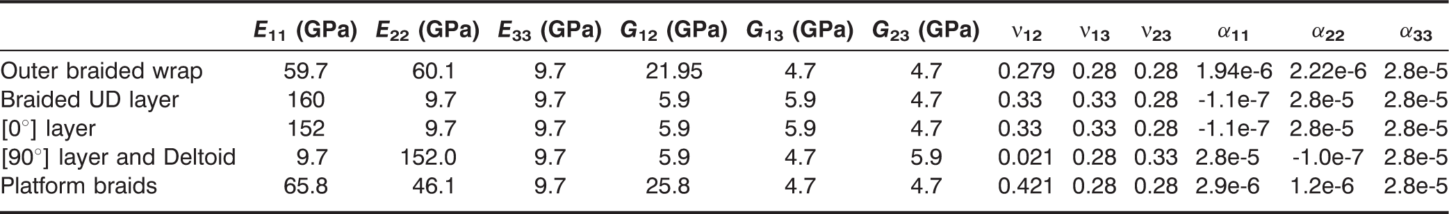
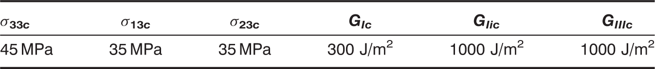
(a) T-piece specimen under pull loading, the grey region is the deformed element; (b) failure modes in deltoid region.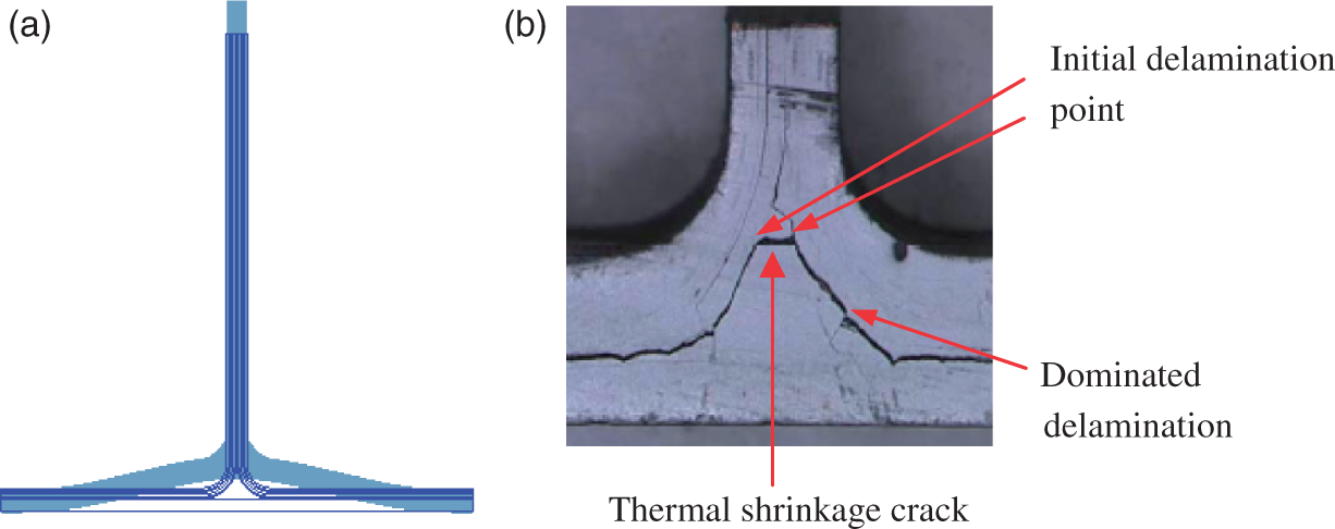
Over the last decade there have been a large number of applications using interface cohesive models to predict delamination of fiber composites [1–12]. However, there have only been a few publications studying the failure mechanism by prediction of delamination of T-piece specimens using interface cohesive elements. Previous work [7] initially investigated the potential of interface elements in prediction of delamination of T-piece specimens. And previous investigations [1,13] studied the basic failure mechanism of T-piece under T-pull loading using interface cohesive models. This article aims to use a modified interface cohesive model with thermal effects added to investigate the thermal related matrix shrinkage crack in the deltoid region, and the effect of thermal initial cracking on dominated delamination along the interface between radius laminates and deltoid of T-piece. Thermal loading from curing laminates and mechanical T-pull loading were considered in this investigation. Basic materials of laminates are given in the Tables 1 and 2 [1], geometry of T-piece and T-pull loading were also taken from [1], and clamped restraints on the foot of T-piece is shown in Figure 2. The temperature change 175°C from curing process was used to investigate the thermal shrinkage cracks in the deltoid of T-piece.
A half 2D model. Materials properties. Interlaminar material strength and fracture energy.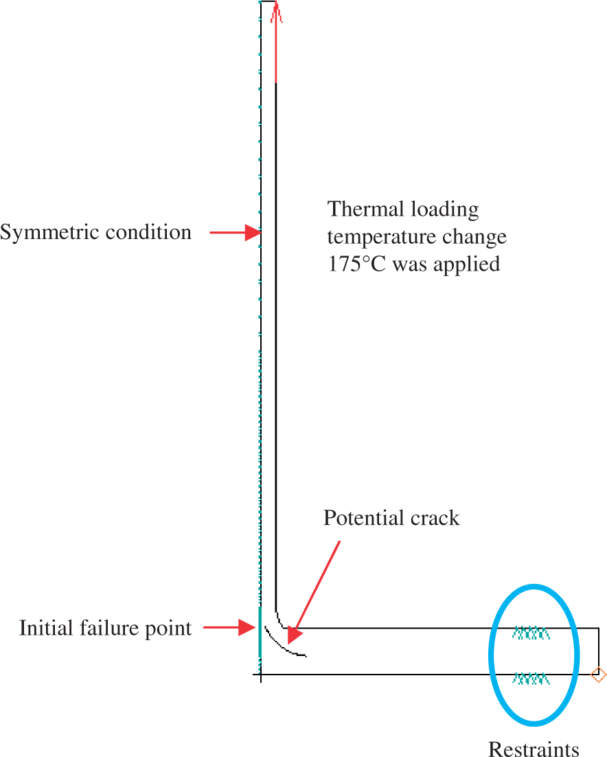
A MODIFIED INTERFACE COHESIVE MODEL WITH ADDED THERMAL EFFECTS
The numerical approach in this work is a modified interface cohesive model which adds thermal effects in the formulation of interface cohesive elements. Thermal and mechanical relative displacements are proposed to be applied together for the study of cohesive interfacial behavior. Firstly, the damage initiation state variable F(ϵ0) is proposed to be assessed by a quadratic formula given in Equation (1):
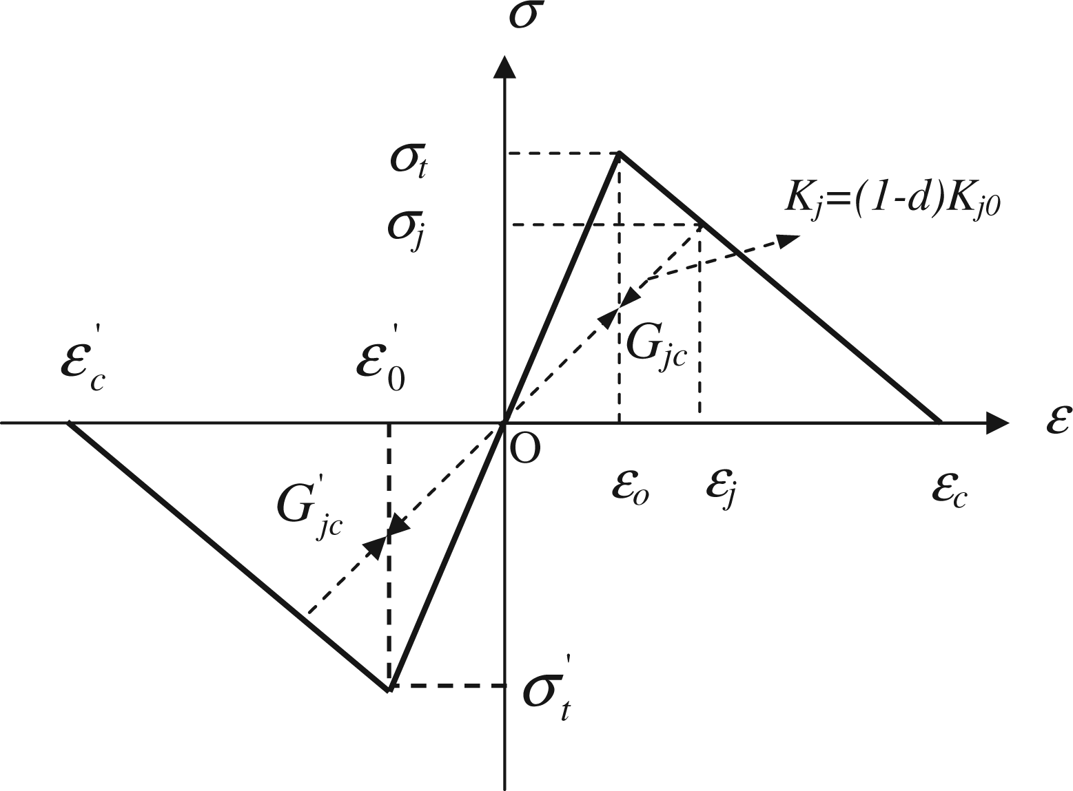
A general bilinear softening damage law.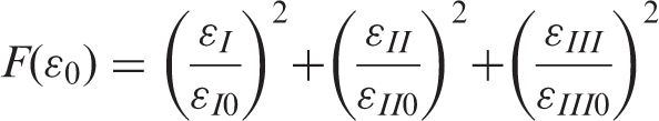
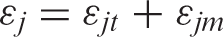
Each relative displacement ϵj (j = I, II, III) in Equation (1) can be accounted by a simple superposition as:

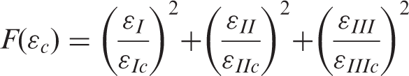
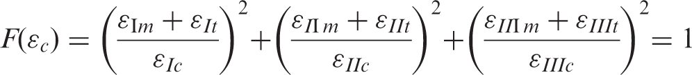
Delamination propagation is proposed to be assessed by the fracture state variable F(ϵc), which can be accounted by Equation (4). Figure 3 shows a single fracture case, when fracture occurs F(ϵc) = 1, this leads ϵj = ϵjc (j = I, II, III), the critical relative displacement:
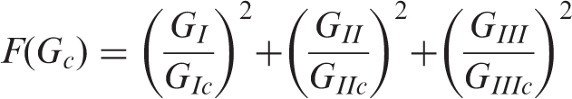
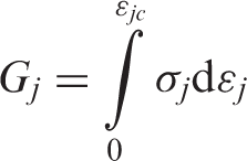
Actually, Equation (4) presents a mixed mode fracture case in which all contribution from three fracture modes are included. Corresponding fracture energy state variable F(Gc) accounted by Equation (5) becomes a unit state when mixed fracture occurs. In single fracture case shown in Figure 3, when F(Gc) = 1, Gj = Gjc (j = I, II, III):
Using Equation (2), Equation (4) can be rewritten as Equation (6) at fracture occurred:
This integral needs the relationship between tractions and relative displacements shown in Figure 3, which can be expressed by the Equation (8) [2–4,8]:
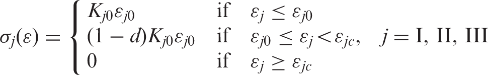
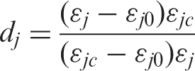
The damage scale d in Equation (8) is proposed to be expressed by a quadratic relationship:

Using the geometrical triangle relationship shown in Figure 3, dj can be defined by Equation (11) [8]:
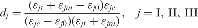
Replacing ϵj by ϵjt + ϵjm, dj can be expressed as follows:
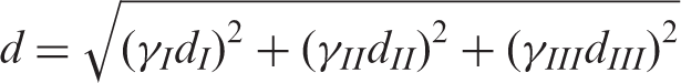
The damage coupling factor γ j in Equation (9) is determined as 0 ≤ γj ≤ 1.0, j = I, II, III.
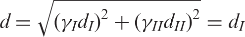
For the single fracture mode, for example, in opening mode, j = I, γI = 1.0 and all others are zero. Therefore, the damage scale d = dI. For the mixed fracture mode in this investigation of plain strain case, the value of γj is derived as follows. First, assume the amount of total damage scale in mixed facture mode equals the value of damage scale in the pure single mode I case. This can be expressed as follows:
It should be noticed that γj in 3D mixed fracture mode can be determined in the same way as that used in this 2D case.
An Interface Cohesive Element
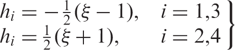
Using Equations (1)–(14) given in the last section, the constitution of 2D interface cohesive element shown in Figure 4 can be expressed as a same format as that in references [2–4], and partly repeating as follows:
A linear 2D interface cohesive element.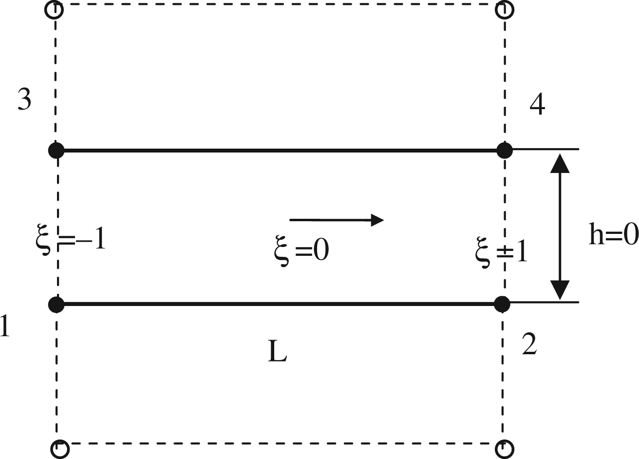
Using virtual work to compute the internal nodal forces, 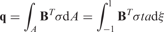
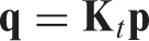
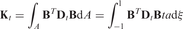
In Equation (17), 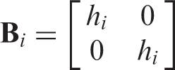
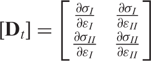
In Equation (20), the normal and tangential components of the traction acting on the interface in the cohesive process zone can be derived by the relationship between tractions and relative displacements given in the Equation (8), and the damage scale d with coupled three fracture modes. It should be noticed that the nodal relative displacements, 

Equations (1)–(23) were used to develop a linear 2D interface cohesive element shown in Figure 4 through a user subroutine in ABAQUS [14], which was used in the investigation of a plain strain case presented in this article. However, the function to account all three fracture modes mentioned in last section are available in the developed user subroutines.
A Compression Model in the Material Softening Damage Law
Figure 3 also shows a proposed compression model which deals with the compressive failure at interface as an opposite failure case against opening fracture.
Modeling Thermal Shrinkage Cracks
A half plane strain model of T-piece is shown in Figure 2. Except the symmetric condition (horizontal movement restrained in the middle plane of web), the middle point on the top of web of T-piece was supported vertically. Four-noded quadrilateral plane strain elements CPE4I from ABAQUS were employed in this modeling. Interface cohesive user elements were inserted in the potential crack area, that is, deltoid region, and the interface between laminate radius and deltoid. Mesh density in crack potential area was limited by the critical length 0.36 mm calculated from the linear fracture mechanics based on formula as Equation (24):
A released restraint condition on the foot of T-piece referred to Figure 2 was applied firstly to study the effect of temperature change from curing laminates on the behavior of T-piece. The temperature change 175°C as a thermal loading was applied on the entire mesh of T-piece. General material properties and fracture toughness are given in the Tables 1 and 2 respectively, which were taken from [1]. Figure 5(a) shows the deformed deltoid region in a half mesh which shows that there was no significant cracking simulated by interface cohesive user elements. This is because the relative thermal coefficients Δαj, worked out from Table 1, are small which have not produced enough thermal relative displacements at interface under given temperature change. The foot of T-piece was freely rotating in this case, thus deltoid region was not deformed much. When restraint was given by clamping the foot of T-piece, significant compression in the deltoid was observed, and material compressive failure simulated by interface cohesive user elements is shown in Figure 5(b). This implicated that materials would fail in deltoid when improper restraints are applied in curing composite T-piece, and failed materials would incur cracks in the deltoid when specimens cool down and restraints are released after curing. This was observed in manufacturing some T-piece components.
(a) Deformed deltoid region in a half mesh due to thermal effects without restraints; (b) deformed deltoid region in a half mesh due to thermal effects with restraints.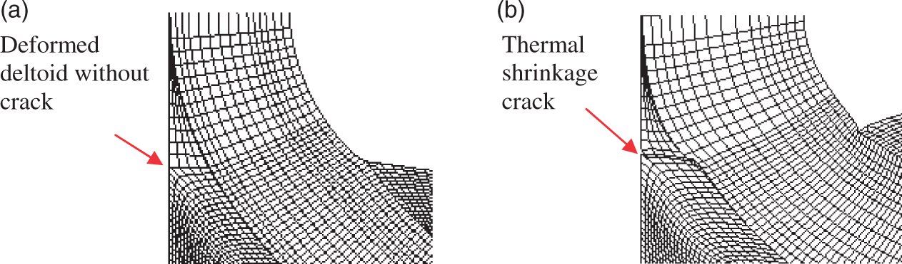
Predicting Delamination of T-Piece with Thermal Initial Crack
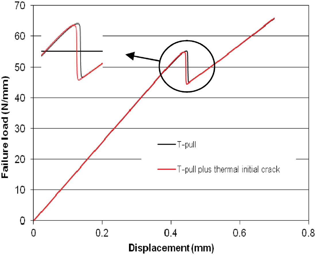
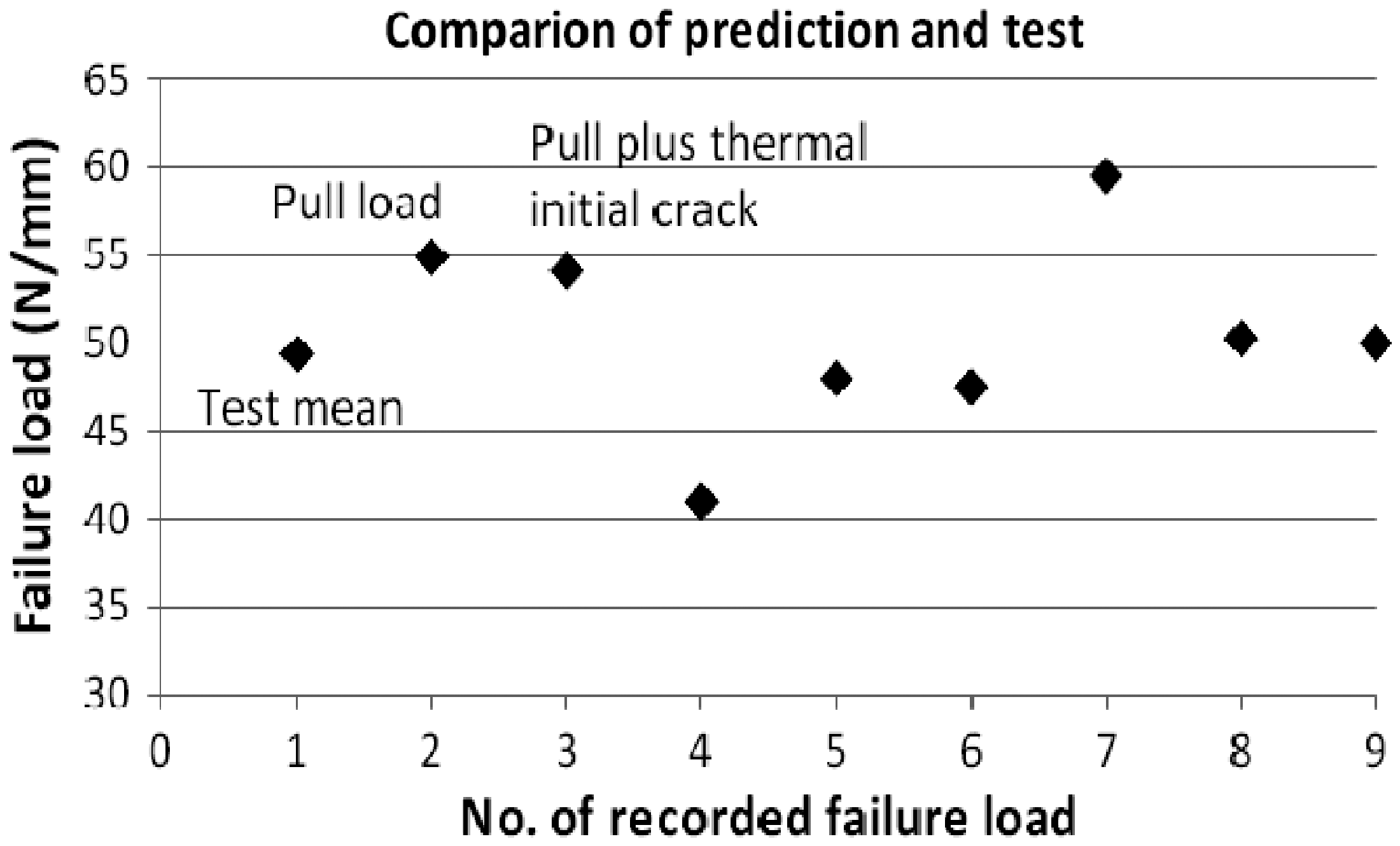
Based on the modeling work presented in last section, investigation of the effect of thermal initial crack on delamination was carried out in which failed materials in deltoid due to curing temperature as a thermal initial crack was existing. Figure 6(a) shows delamination and thermal shrinkage crack in deltoid region. Delamination without thermal initial crack is shown in Figure 6(b). Load–displacement curves for two cases, pull and pull plus thermal initial crack, are given in Figure 7, which shows two curves are mostly in superposition, a slight difference can be seen at the point of failure load. Figure 8 shows predicted failure loads together with experimental solutions marked by recorded numbers 4 to 9. In Figure 8, the first recorded failure load gives the average tested value 49.4 N/mm, which was worked out from six specimens with all different manufacturing quality levels [15]. It should be noticed that the tested mean 55 N/mm reported in [1] was obtained as an averaged value from specimens with good quality only. The second and third recorded numbers in Figure 8 give the predicted failure load 54.9 and 54.1 N/mm for T-pull loading case and T-pull plus thermal initial crack, respectively. Both predicted failure loads are higher than the tested average failure load 49.4 N/mm by 10%. Comparing to the pure T-pull loading case, the reduced percentage of predicted failure load in the loading case of T-pull plus thermal initial crack is less than 1.5%. This indicates that the effect of thermal initial crack on delamination is not significant in this T-pull loading case.
(a) Delamination due to pull plus thermal initial crack; (b) delamination due to pull with no thermal initial crack. Load–displacement curve. Failure response.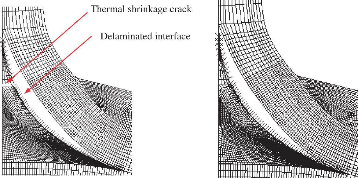
DISCUSSION AND FUTURE WORK
Development and application of a modified interface cohesive model with added thermal effects are presented in this article. This model was used to simulate the matrix thermal shrinkage crack and delamiantion propagation in deltoid of T-piece under pull loading. Investigation indicated that some improper restraints to T-piece specimens in curing process will bring so called thermal shrinkage cracks in deltoid region. However, this sort of thermal related matrix initial crack had limited effects on the capacity of T-piece to resist T-pull loading. Radius laminates were the main load carrier in the pull loading case. It should be noticed that above comments were given based on the comparison using the average tested value of failure loads [1,15]. Present experimental work has not yet supplied exact individual failure mechanism of T-piece with or without thermal initial crack in deltoid region. It is the modeling simulation that filled the gap in investigation of such failure mechanism. Although this investigation was single pulling case only, supplied information is considerable for some T-piece related composite components which are mainly subjected to pulling loads.
Future work is expected to investigate thermal effects in more loading cases to study general effects of thermal matrix initial crack on the delamiantion of T-piece specimens under bending, and mixed loading case with pulling and bending. The later one is actually a real loading condition for some components such as aero engine blades. Future work will entirely assess the general capacity of T-piece specimen under combined loading case. This would be valuable in the progressive failure analysis of practical composite blades which are doubly curved bodies. A study of fiber orientation in this sort of curved blades was given in author's previous work [16]. Finally, this modified interface cohesive model with added thermal effects can be applied in a wide range of investigation of composite components under the service load with temperature change in the future.
Footnotes
Nomenclature
= Damage initiation state variable = Initial damage relative displacement = Relative displacement = Critical relative displacement = Interface strength = Interface traction = Thermal relative displacement = Mechanical relative displacement = Relative thermal coefficient = Temperature change = Fracture state variable = Fracture toughness = Fracture energy state variable = Interface initial stiffness = Interface reduced stiffness = Damage scale = Damage coupling factor = Nodal forces of interface cohesive element = Nodal relative displacements of interface cohesive element = Tangent stiffness matrix of interface cohesive element = Nodal shape function of interface cohesive element = Constitute relationship of cohesive materials = Opening relative displacement relating to mode I crack = Sliding relative displacement relating to mode II crack