
Abstract
This study investigates a novel thermoplastic prepreg rig and method of manufacturing prepregs using aqueous wet powder impregnation. The compact, easily maintained prepreg rig is suitable for rapid prepreg manufacturing in laboratory-scale research. The rig could be used with a wide range of thermoplastic powders and reinforcing fibres. Tests were conducted to study various settings and parameters, including the polymer–carrier ratio, winding speed and fibre tension. The study examined the effectiveness of the liquid carrier in suspending the polymer powder and tested the consistency of the rig in resin pick-up. The findings indicate that a winding speed of 4.2 to 5.7 m/min with a low fibre tension is ideal for producing S2-glass/PAEK prepregs. The amount of polymer pick-up by the fibre tow remained constant throughout the winding for 10, 20, and 30 wt% slurries. However, higher wt% slurry settings resulted in resin agglomeration on the rollers, causing significant fibre breakage.
Introduction
Thermoplastic polymers offer valuable advantages for manufacturing fibre-reinforced composites compared to thermosetting matrices. These advantages include faster processing, lightweight, inherent toughness, flame retardancy, higher strength and stiffness, greater impact and chemical resistance, recyclability, and infinite shelf life without the need for refrigeration.1–5 High-performance thermoplastic polymers are therefore promising alternatives to thermosetting ones and there has been an increasing interest on thermoplastic composites in different industries. The choice of polymer for manufacturing high-performance thermoplastic composite parts is critical, particularly for high-speed civil transport materials used in supersonic aircraft. At speeds of Mach 2.0 to 2.4, skin temperatures can reach over 200°C, requiring materials with excellent thermal and mechanical properties in such operation conditions.6,7 Thermoplastic matrices have potential for lightweight, high-strength fibre-reinforced composites, but face challenges such as sensitivity to temperature and low service temperatures of traditional thermoplastics. This limits their use in high-temperature applications and requires investigation of new systems for aerospace industry . 8 High-performance thermoplastics such as the polyarylether ketone (PAEK) family, exhibit excellent mechanical properties, chemical resistance, and thermal stability up to temperatures above 150°C, making them ideal for high-temperature applications. They offer enhanced heat resistance, durability, toughness, strength, and the ability to be moulded into tight-tolerance parts, making them suitable for developing multi-functional thermoplastic composites to overcome current limitations.9–12
Manufacturing thermoplastic composites poses a challenge due to the solid state of the polymers, making it difficult to impregnate fibres with the resin matrix. This is, in contrast, to liquid thermosets like epoxy, which offer better fibre wet-out during impregnation or prepregging processes. The viscosity of thermosets is less than 100 Pa.s at a processing temperature, making them easier to handle and process.13,14 However, the high melt viscosity of thermoplastics, which can exceed 550 Pa.s, makes it challenging to achieve full impregnation and can lead to poor resin wetting, limiting the use of continuous fibre-reinforced composites. This issue is critical for applications such as carbon fibre/PAEK used in expensive aerospace products. Poor resin impregnation can result in a significant decline in mechanical properties.15,16 To manufacture thermoplastic prepreg effectively, the resin must surround individual fibre filaments within a bundle during the impregnation process. The goal is to ensure a homogeneous flow of resin to achieve balanced and full impregnation. Heat is applied to ensure adhesion of the resin to the fibres. Different impregnation methods have been developed, including melt impregnation, film stacking, fibre commingling, solution impregnation, and powder impregnation.
Melt impregnation coats fibres with molten polymer, but fully polymerised thermoplastics have high viscosities that are two to three times greater than common thermosets. Therefore, the viscosity of a molten polymer should be low enough for good and uniform impregnation. 17 This difficulty limits the process, as impregnation can take up to 6 h to incorporate medium viscosity PEEK into a carbon fibre roving without external forces. 18 A pin-assisted melt process has been found to increase impregnation rates by pulling fibre roving over rollers to force molten resin into the bundle. More rollers increase impregnation from both sides, resulting in a higher wet-out for glass fibre/polypropylene composites. 19 Improvements can also be made by increasing impregnation time, resin temperature, and fibre tension. 20 However, too high temperatures can result in polymer degradation, and passing fibre through viscous resin can cause filament breakage and excessive abrasion.21,22 Melt impregnation can damage fibre and is difficult for high-temperature and high-viscosity polymers like PAEKs. Pressure build-up can also occur when the fibre tow passes over the wedge-shaped region between the roving and the roller. 18 The earliest appearance of the melt impregnation method dates back to 1976 in a US patent US3993726. 23
Due to its relative ease of production, film stacking method was widely used in early production of thermoplastic composites. 24 Film stacking involves heating and pressing layers of lamina with fibre reinforcement and thermoplastic polymer to create a composite sheet. It is a melt impregnation technique that requires adequate pressure to ensure the resin flows into the fibres.25,26 Film stacking has limitations, including long cycle times, concentration of fibres, reduced permeability, and unsuitability for high melt viscosity polymers, resulting in resin-rich areas. This makes it unattractive on a commercial scale.27,28
Commingling reinforcing fibres with thermoplastic polymer in fibre form minimizes the flow distance of the resin. The resulting hybrid yarn is heated and pressurised to melt the polymer resin and wet-out the reinforcing fibre for composite production.29–31 The studies have evaluated commingled composites in terms of manufacturing, impregnation, and consolidation modelling, and resulting mechanical and physical properties. Commingled yarns can be adjusted to control the fibre–matrix ratio, and factors such as volume fraction and interlacing degree can affect the final product.29,32–35 Although high melt viscosity resins like PEEK can be processed successfully, higher pressure and longer time may be required for CF/PEEK composites compared to powder and sheet impregnated methods. 36 Imperfect interlacing of fibre constituents can result in a longer impregnation time, resin-rich areas, or unimpregnated areas in the composite part. 37 De-mingling of commingled prepregs is possible under tension, leading to improper mixing of constituents.36,38 This method is limited to thermoplastic resin in fibre form, with high processing costs.
Solution processing dissolves polymer resin in a solvent to produce a low viscosity solution for impregnating fibres. However, this method has drawbacks, including environmental concerns due to toxic solvents and high void contents in the final product due to solvent entrapment.39–43 The use of aggressive solvents like formic acid is required for solvent-resistant semi-crystalline polymers such as PA, and compatible solvent systems for highly solvent-resistant polymers such as PAEK resins, which are scarce.44–47
Among all the other impregnation techniques, powder impregnation is gaining popularity due to its low-cost manufacturing and processability. It can be classified into two categories: dry and wet powder impregnation, both involving incorporating fine thermoplastic polymer powder between fibre filaments but differ in how resin particles are deposited on fibres. Dry powder impregnation involves passing the fibre tow through a chamber of polymer powder, and the attachment of resin particles to the fibres varies by techniques applied. Ganga48–50 patented a method of impregnating 20-micron PA powder by particle fluidisation, coating the impregnated glass roving with an outer layer of a different or same polymer and melting it. Rath et al. 51 fluidized Nylon-12 particles and produced prepregs with a fibre volume range of 20 to 50 %. Other similar works with different polymers and grades of CF have also been carried out.52,53 Muzzy et al. 54 charged and fluidized PEEK or LaRC-TPI powders electrostatically and deposited particles on spread tow fibres to manufacture AS-4/PEEK, S2-glass/PEEK, and AS-4/LaRC-TPI. Non-conductive S2-glass required considerably more time in the deposition chamber for PEEK impregnation than AS-4 carbon fibre.55–58 A method studied by Iyer and Drzal 59 showcased a controlled and uniform method of powder deposition by using acoustic energy. They utilised an acoustic source in order to subject the powder bed to low frequency vibrations. Ramani et al. 60 developed an electrostatic spray process that employs both mechanical impregnation and electrostatic adhesion of resin particles. The process involves heating the fibre tow with a hot nitrogen torch, moistening it for better electrical conductivity, and passing it over a grounded spherical surface for spreading. The effect of fibre velocity, corona voltage, and powder mass flow on the degree of powder deposition was investigated. 61 Dry powder impregnation technologies offer benefits like independence of matrix viscosity and avoidance of toxic solvents, but have drawbacks such as difficulty in controlling fibre volume fraction and the need to remove excess resin. Gas-assisted powder flow methods have disadvantages such as uneven resin overlay, irregular particle distribution, and the risk of dust explosion. Expensive powder coating equipment may also be a concern, and the methods are primarily suitable for conductive fibres like CF and not insulating fibres like GF.
The wet powder technology is an alternative to dry powder one based on the concept of suspending polymer particles in a liquid carrier and passing fibre reinforcement through the slurry tank containing the aqueous medium to pick up the resin particles. Taylor 62 investigated a dispersion of a powdered plastic resin in water, which was made thick by means of water-thickening materials such as polyethylene oxide and hydroxyethyl cellulose. The dispersion was then applied to fibrous textile to distribute the resin over the fibres. Most of the methods follow the same procedure but use other compositions of liquid carrier.63–65 PEEK and LaRC-TPI were reportedly suspended in aqueous solutions of ammonium salts of polyamic acid. Utilising this suspension helped with particle dispersion, as a fibre–matrix interface binder. High-performance continuous carbon fibre composites were manufactured with fibre volume content of 36 to 61 % for CF/PEEK, and 38 to 49 % for CF/LaRC-TPI. Various processing conditions including fibre tension and resin concentration can influence the properties of the consolidated laminate.66,67 Vodermayer et al. 68 employed an aqueous dispersion containing water, polymer powder, and 1 % additive (chremophor surfactant), and further developed a model of powder impregnation of infinite number of fibres. They stated that with decreasing particle diameter, the powder concentration in the dispersion and consequently the viscosity of the dispersion increased, and concluded that the use of powders with a particle diameter of about 15 to 20 μm is beneficial. Chary and Hirt 69 created a surfactant solution aqueous foam of the thermoplastic resin by using a nitrogen gas, and deposited the foam on AS-4 carbon fibre. A tube furnace was used to fuse the polymer onto the fibre. Steggall et al.70,71 developed a powder slurry impregnation method by injecting slurry of HDPE powder and water in a closed mould containing biaxial glass fabric and vacuuming down the mould to impregnate the fabric. Composites with an average fibre volume fraction of 65 % were produced, and a model was developed to predict the void fraction. Ho et al. 72 employed a wet impregnation route for polymer impregnation to produce unidirectional PEEK and PVDF carbon fibre tapes, with a fibre volume content ranging between 58 and 62 %, by preparing an aqueous slurry based on polymer suspension. Aerosol OT (AOT) and Cremophor A25 were used in low concentrations as the mean for suspending the polymer powders in water. Song et al. 73 studied the effect of two surfactants (Triton X-100 and PEG) on preparation of powder slurry for preparation of thermoplastic prepregs. The results showed that the use of Triton X-100 yields to a better infiltration of PEEK powder in fibre filaments, while PEG would show stronger steric hindrance. Stability of the slurry was improved by using a compound system to prepare the PEEK suspension. Fibre volume contents up to 60 % was observed. Shamsuddin et al. 74 produced rayon fibre composites reinforced with PHB nanocomposites using wet powder impregnation. In their study, rayon fibres were drawn through the impregnation bath containing PHB dispersed in water using Cremophor A25 as a surfactant. Various pins were put inside the impregnation bath to increase the fibre pre-tension to enhance fibre spreading. Composites with approximately 50 % fibre volume fraction were produced.
Based on reviewing various thermoplastic prepreg manufacturing methods, it has come to light that traditional manufacturing methods, such as melt impregnation, film stacking, and fibre commingling, either require expensive equipment and a costly procedure, or usually are incapable to process high-temperature matrices such as PAEKs. An aqueous powder impregnation technology can eliminate many of the aforementioned problems and provide numerous benefits in comparison to many other traditional methods. This paper presents a novel thermoplastic prepreg manufacturing method utilising wet powder impregnation. The designed and manufactured prepreg rig provides grounds for a very effective thermoplastic prepreg production in terms of costs, scale, and suitability.
Drum winding unidirectional prepreg rig
Concept
The first challenging step of this work is to employ and investigate the practicality of an effective method of thermoplastic resin impregnation, and subsequently prepreg manufacturing. The main derivatives affecting the choice for a suitable manufacturing method are charted in Figure 1. For this purpose, three main factors including suitability, cost, and scale are considered. Key factors considered for the manufacturing process and rig development.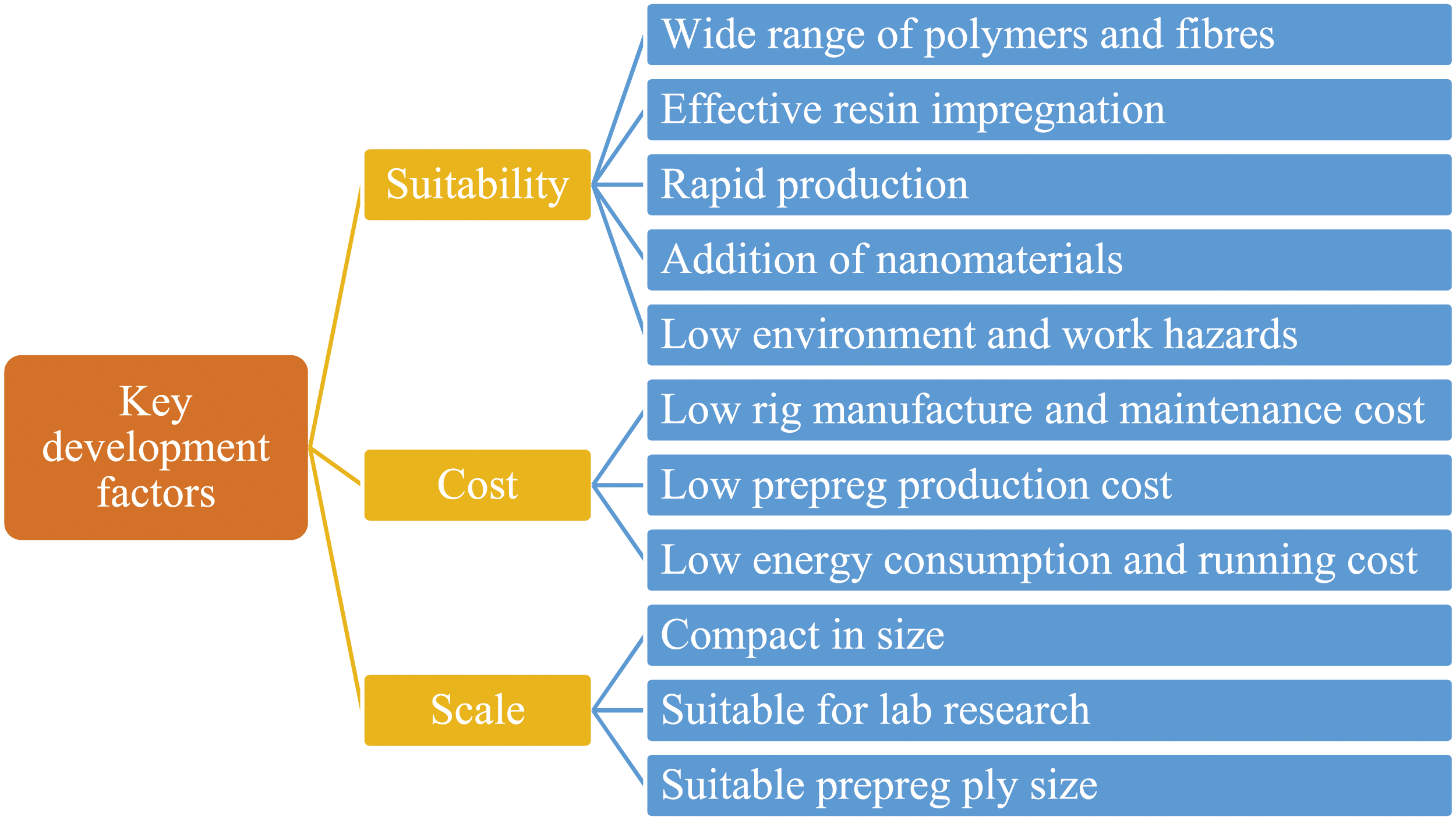
Wet powder impregnation would be the best method for this study. It is cost-effective, versatile, and safe without the need for hazardous agents. It also eliminates the need for expensive coating or melting devices. In summary, aqueous powder impregnation offers considerable advantages over other methods including: • Different particle sizes can be used, which is notably important for impregnating fibre cloth that cannot be spread. • No polymer solubility limitations compared to solution processing. • Very low slurry viscosity compared to melt impregnation. • Easy incorporation of additives and modifying fibre–matrix interface. • Inexpensive equipment and simple guiding systems without use of die. • Short melt state time and short resin flow length. • Easy control over fibre–matrix ratio by adjusting polymer proportion in the slurry. • Easy and safe handling of the process.
Future investigations will focus on studying the effect of nanomaterials on composite laminates. To achieve a homogenous blend of the polymer resin and additives, wet powder impregnation appears to be the most suitable method. It allows for thorough mixing of additives with the polymer powder to create a homogenous suspension. Dry powder impregnation cannot achieve this, making it difficult to coat reinforcing fibres evenly. Wet powder impregnation provides a cost-effective and compact solution for lab-scale research and development. This method presents an interesting opportunity for further investigation.
This study aims to establish a technique for manufacturing unidirectional (UD) S2-glass/PAEK composite unidirectional thermoplastic prepregs. This involves impregnating continuous fibre roving to produce towpreg, which can be combined to form a UD tape. The number of bobbins required depends on the desired tape width, with wider tapes requiring more bobbins and greater investment. Certain fundamental criteria shall be met in order to design and manufacture an effective laboratory scale UD thermoplastic prepreg rig, which are: • Control over the resin to fibre ratio, that is, fibre volume content. • Control over the thickness and fibre spread.
This study utilises wet impregnation technology for drum winding of continuous fibre roving to develop UD prepreg, inspired by the industry practice of filament winding. This method is traditionally used for circular or oval hollow sections, like tanks and pipes. 75 Instead of thermosetting resin, a suspension of polymer powder in a liquid carrier is used. The fibre tow is wound close to the previous array, creating a sheet of wet UD prepreg on the drum, which can be melted on heating and removed to produce UD prepreg.
Design
The proposed method for manufacturing UD thermoplastic prepreg uses a single fibre bobbin on a winding drum, reducing production cost and rig size. However, the size of the prepreg is limited by the drum size and the production is not continuous. This method is ideal for small-scale research and development. The design consists of several primary components. This includes a package holder, resin bath, fibre spreader, guiding rollers, and a winding drum. While a linear actuator moves the fibre tow across the length of the drum, the winding system pulls the fibre through the guides, soaking it in a polymer slurry before passing it through the fibre spreader for resin impregnation. The wet fibre tow is wound onto a winding drum, with the speed being controlled to ensure parallel placement. After winding, a heater is used to evaporate water and melt the polymer for permanent adhesion.
Rig assembly
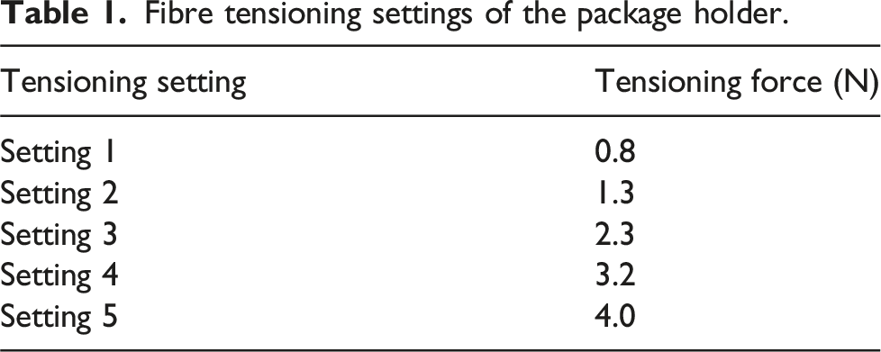
Figure 2 shows the schematic design of the assembled drum winding UD prepreg rig and the manufacturing processes. The package holder, mounted on the actuator, comprises of a tube loaded on a bearing, attached to a large pulley. The friction between the leather band and the pulley controls the initial tensioning force on the fibre tow, with five different options available as per Table 1. The fibre spreader system uses mechanical vibration and spreading rollers to obtain a flat array of fibres. The rollers push the polymer particles into the fibre bundle and cause the filaments to slide and reduce the thickness of the towpreg. The polymer particles also act as spacers between the filaments to further spread the tow.
76
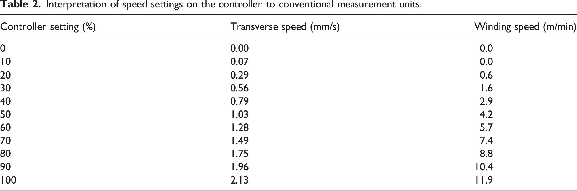
The polymer is heated and melted on the surface of the drum (treated with release agent). The transverse speed of the linear actuator and the winding speed of the drum can be adjusted using a speed controller unit. Both speeds are assigned in percentage with 0 % being stop/off and 100 % being full speed. These percentages are interpreted in mm/s for the transverse speed and in m/min for winding speed (line speed) as per Table 2. Transverse and winding speeds are adjusted to accommodate minor overlap at the start of winding, preventing gaps between fibre tows. The winding speed is chosen to avoid excess resin slurry on the drum that would make squeezing off excessive resin difficult. After the winding is complete, the drum with the wet prepreg is moved towards the end of the line and heated for at least 1 h to remove water residues and obtain a dry prepreg. Then, the drum is placed in an oven for final melting and adherence of the polymer on the fibres. After cooling, the prepreg sheet is cut from the drum. Design of the assembled drum winding thermoplastic prepreg rig comprising several parts including package holder, guides, rollers, resin bath, actuator, drum, and heater. Fibre tensioning settings of the package holder. Interpretation of speed settings on the controller to conventional measurement units.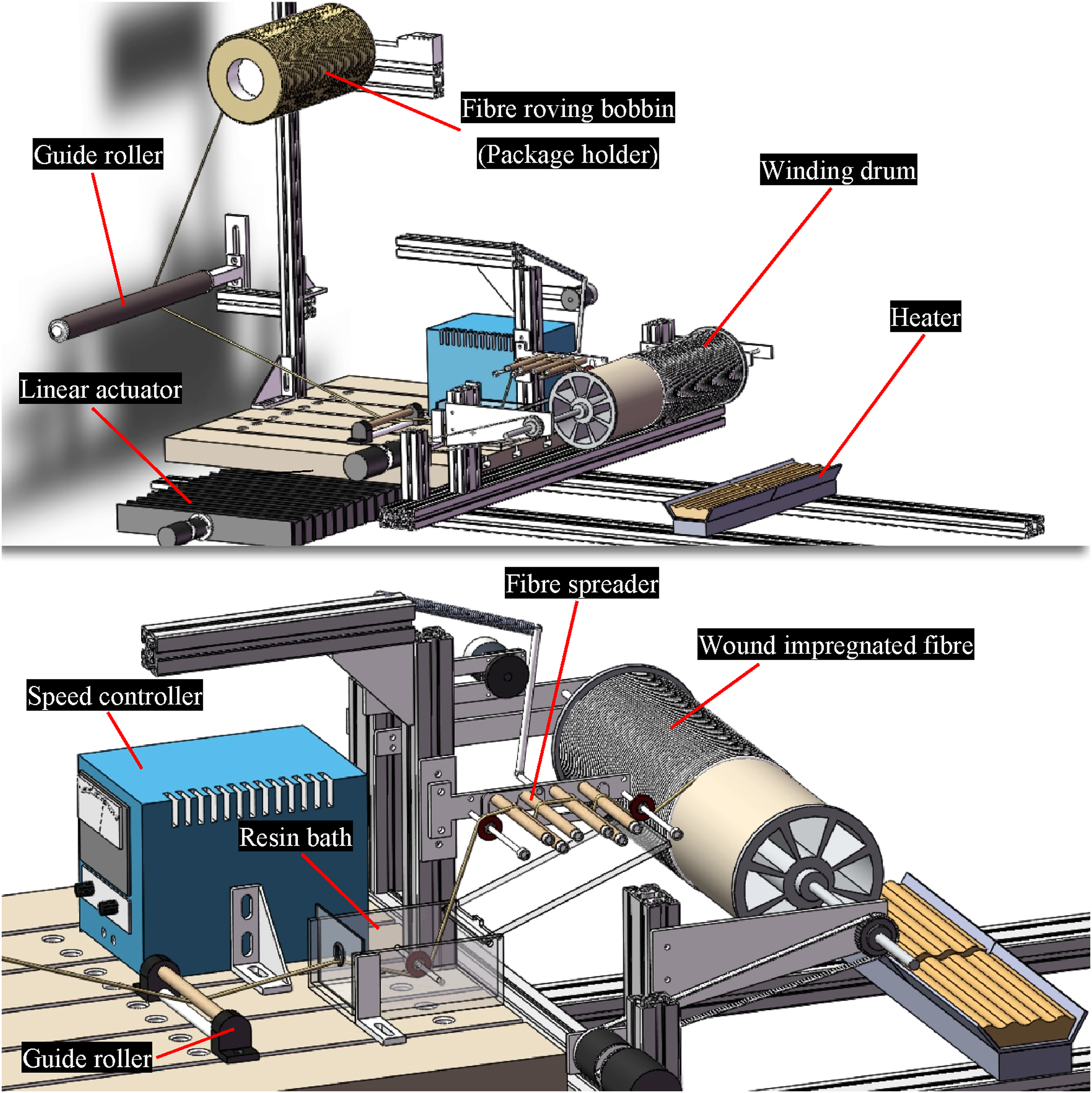
Experimental procedure for method evaluation and optimisation
For an effective investigation of the prepreg rig, different variables that can affect the properties of the prepreg are identified as: • Polymer powder to liquid carrier ratio • Fibre tension • Winding speed • Fibre spreader frequency and amplitude* • Fixed or rotating roller* • Interchangeable end roller*
*Investigated previously. 76
Experiments were designed to investigate resin systems with different polymer content and the effectiveness of the liquid carrier. Different tests were also carried out to identify the effects of other variables on the amount of powder pick-up by the fibre tow. These tests are crucial to evaluate the consistency of the production method and the resulting prepreg materials. The tests are divided into two sections: polymer–carrier and rig setting tests.
Materials
S2-glass fibre roving with a grade of 933-AA-750 supplied by AGY LLC. (USA) was used in this study. This grade consists of numerous G filament (9 microns) continuous glass strands, which has a linear density of 675 g/1000m (TEX), approximately with 4200 filaments bundled together. Fibre strands without mechanical twist are treated with a thermally stable inorganic sizing suitable for high-temperature matrices such as PAEKs. The apparent thickness and width of the received fibre roving are measured 0.20 mm and 2.5 mm, respectively. PAEK polymer was supplied in form of fine powder from Victrex plc. (UK).
Aqueous slurry preparation and tests
Polymer powder was weighed and added to the liquid carrier for mixture. LiquiPowder (L2O) liquid carrier from Tech Line Coatings Inc. (USA) was used. L2O is a water-based system with dispersing, resinous, and thickening agents that helps with even PAEK particle suspension in the slurry. Ratios prepared were 10, 20, 30, and 40 % of PAEK to 90, 80, 70, and 60 % of carrier, by weight, respectively. For instance, 20 g of polymer powder was added to 80 g of liquid carrier to produce a 20 wt% polymer slurry. The constituents were mixed in a closed mixing pot and stirred with an overhead lab stirrer for 30 min at a low speed of 500 r/min, followed by 30 min at a higher speed of 1000 r/min. Low stirring speeds were selected to prevent excessive foaming and air bubbles from forming in the slurry. Next, the slurry was transferred to a degassing chamber and subjected to a vacuum pressure of 0.8 Pa for 60 min to eliminate any remaining air. Throughout the degassing process, the slurry was gently stirred with a magnetic stirrer to prevent particle settling.
For a better understanding of colloidal stability and sedimentation properties of the prepared slurries, the turbidity of selected samples was measured using a Formulaction Turbiscan AGS, as seen in Figure 3. Here, 20 mL of the prepared and readily agitated (magnetic stirrer for 30 min) sample slurries were dispensed into screw-top glass vials and were mounted into the electrically controlled temperature blocks. The temperature of all the blocks were set to 25°C (room temperature), to represent the ambient temperature of the prepreg rig working area. Both transmitted and backscattered light were measured over the whole height of the vials every 5 min for a duration of 120 min (25 cycles). This duration shall give an extended overview of the turbidity behaviour of PAEK slurries when put inside the resin bath and undergo the prepreg production process. Turbiscan AGS unit comprised of different parts for measuring turbidity.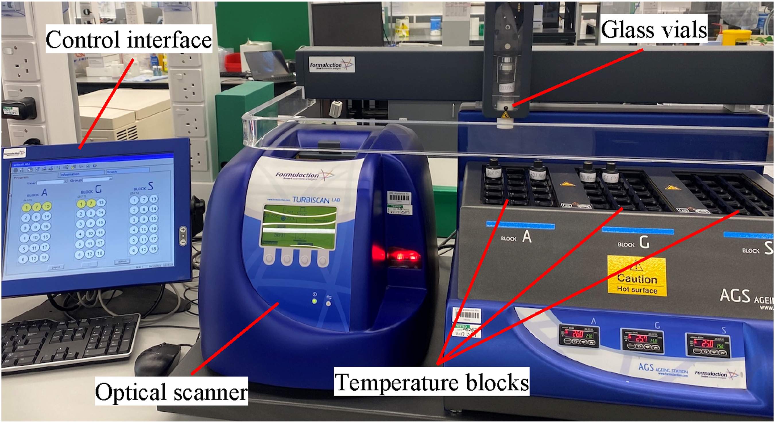
Thermogravimetric analysis (TGA) was carried out using a Netzsch TG 209 F1 Libra to further evaluate the thermal stability of the liquid carrier and the polymer suspensions. Neat liquid carrier and 10, 20, and 30 wt% slurry samples were heated from 25°C to 400°C with a ramp rate of 10°C per minute in nitrogen atmosphere. The change in the mass of the samples was captured and recorded as the temperature increased.
Prepreg rig settings and tests
Apart from the polymer–carrier ratio, other factors contributing to changes in prepreg properties are various settings that are adjustable on the prepreg rig. It is reported that impregnation and fibre spreading depends on several factors and variables regardless of the process and method used.60,77–79 As there are so many parametric variables, it is difficult to assess and optimise the parameters with traditional one-factor-at-a-time method since one cannot identify interactions between the parameters. The goal here is to identify a range in which each setting can be adjusted and consequently optimise each for the best synchronisation. Ultimately, it is preferred to only deal with one variable to customise different prepregs with different fibre volume content. Therefore, the polymer–carrier ratio is chosen as the best option for controlling the fibre volume and it is proposed to keep other identified variables constant.
Winding tests
Here, 20 wt% PAEK slurry, chosen as a moderate value and benchmark, is prepared and added to the resin bath. In the winding tests, two variables are being investigated, that is, fibre tension and winding speed. The fibre spreader is turned off and the spreading rollers are set to rotate. Open guide roller is chosen for the interchangeable end roller. 76 The transverse speed is adjusted in a fashion to allow slight fibre-overlap when the winding process begins. Winding speed is varied from 0.6 to 11.9 m/min and the initial tensioning force is adjusted on the package holder via the pulley and band mechanism, varying from Settings 1 to 5 (0.8 to 4.0 N), as per Table 1. This test is to visually observe the resin bath, impregnated tow, fibre waviness, fibre breakage etc.
Resin pick-up test
The resin pick-up test is designed to investigate if the amount of resin picked up by the fibre tow remains constant throughout the winding. This test is carried out using the optimum rig settings already investigated in the fibre spread tests, and the findings of the winding tests. In the resin pick-up test, the only variable affecting the amount of PAEK deposited on S2-glass fibres is set to be the polymer–carrier ratio. To investigate this, four different ratios are prepared and investigated, that is, 10, 20, 30, and 40 wt% slurry systems. Here, the linear actuator plate is set to the starting point and the fibre spreader is turned on with the frequency and amplitude set to 5.0 Hz and 6 mm, respectively. These values are identified as optimum ones in the fibre spread tests. The spreading rollers are set to rotate with an adjustable speed and 5 mm guide roller is chosen for the interchangeable end roller.
76
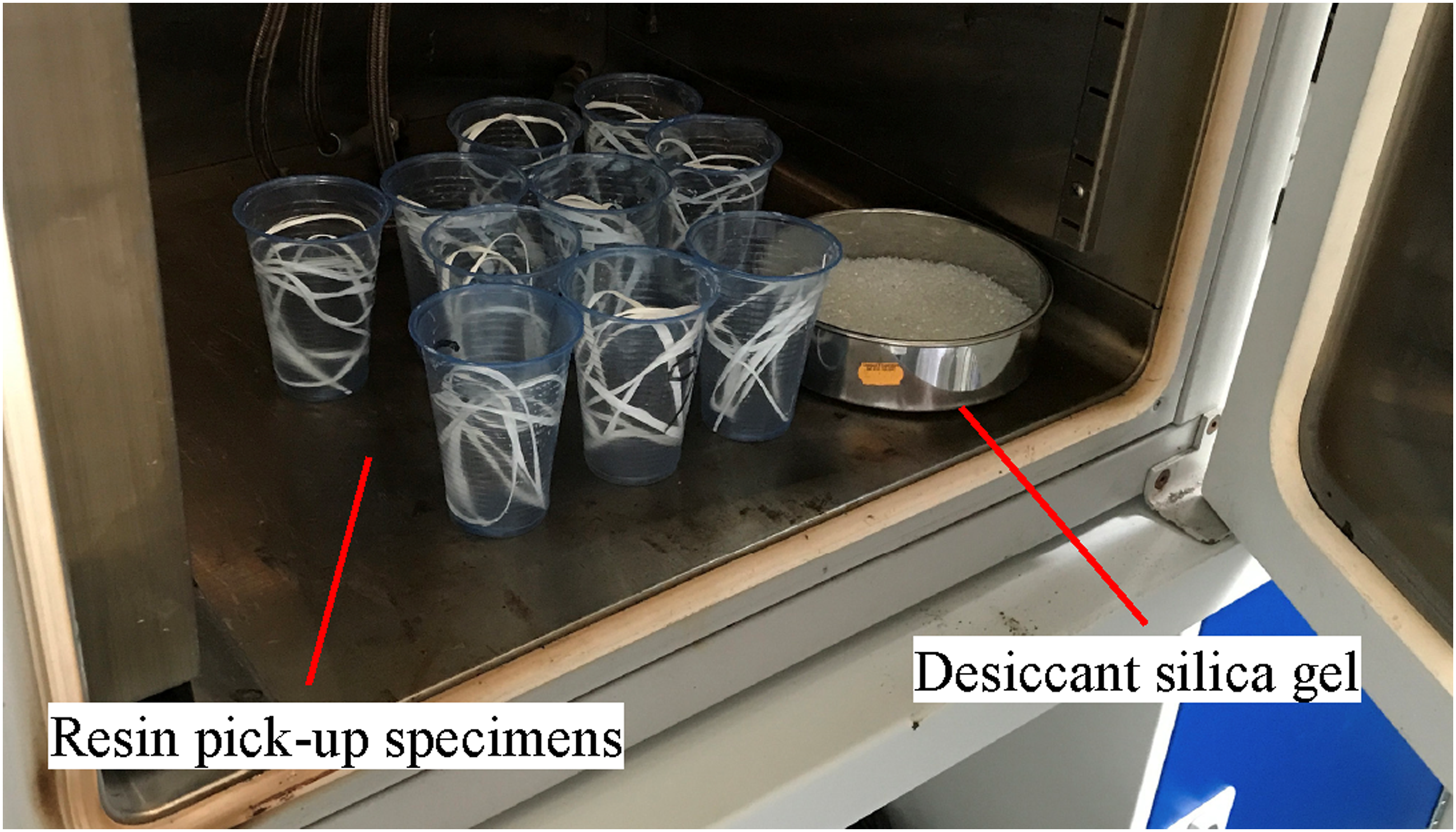
Initial fibre tensioning force is kept constant and is set to Setting 2 (1.3 N) and the winding speed at 4.9 m/min, the prime value identified in the winding tests. The transverse speed is adjusted in a way to accommodate significant gap (20 to 30 mm) between the wound tows on the winding drum. About 10 m of the impregnated fibre tow is wound around the drum. Example of this process is illustrated in Figure 4. The drum continues to rotate while being heated to ensure even distribution of heat. The heater is set to 400°C and the wet composite is heated for 1 h in order to extract water residues from the wet towpreg. The wound fibre tow sample is then cut into 1-m-long specimens for a total of 10 specimens. As seen in Figure 5, cut specimens are then positioned into individual pots and placed inside an oven heated at 150°C for a further 1 h. Desiccant silica gel is also placed inside the oven as a drying agent to help absorbing any remaining moisture in specimens. The sample fibre tows are then weighed immediately after they are removed from the oven to avoid moisture absorption. The weight of all 10 specimens is recorded and compared. The investigation here is to primarily identify whether the resin-pick up by the fibre tow is consistent throughout the winding process or not. Winding impregnated fibre tow on the drum for the resin pick-up test. Drying process of impregnated fibre tow specimens for resin pick-up test.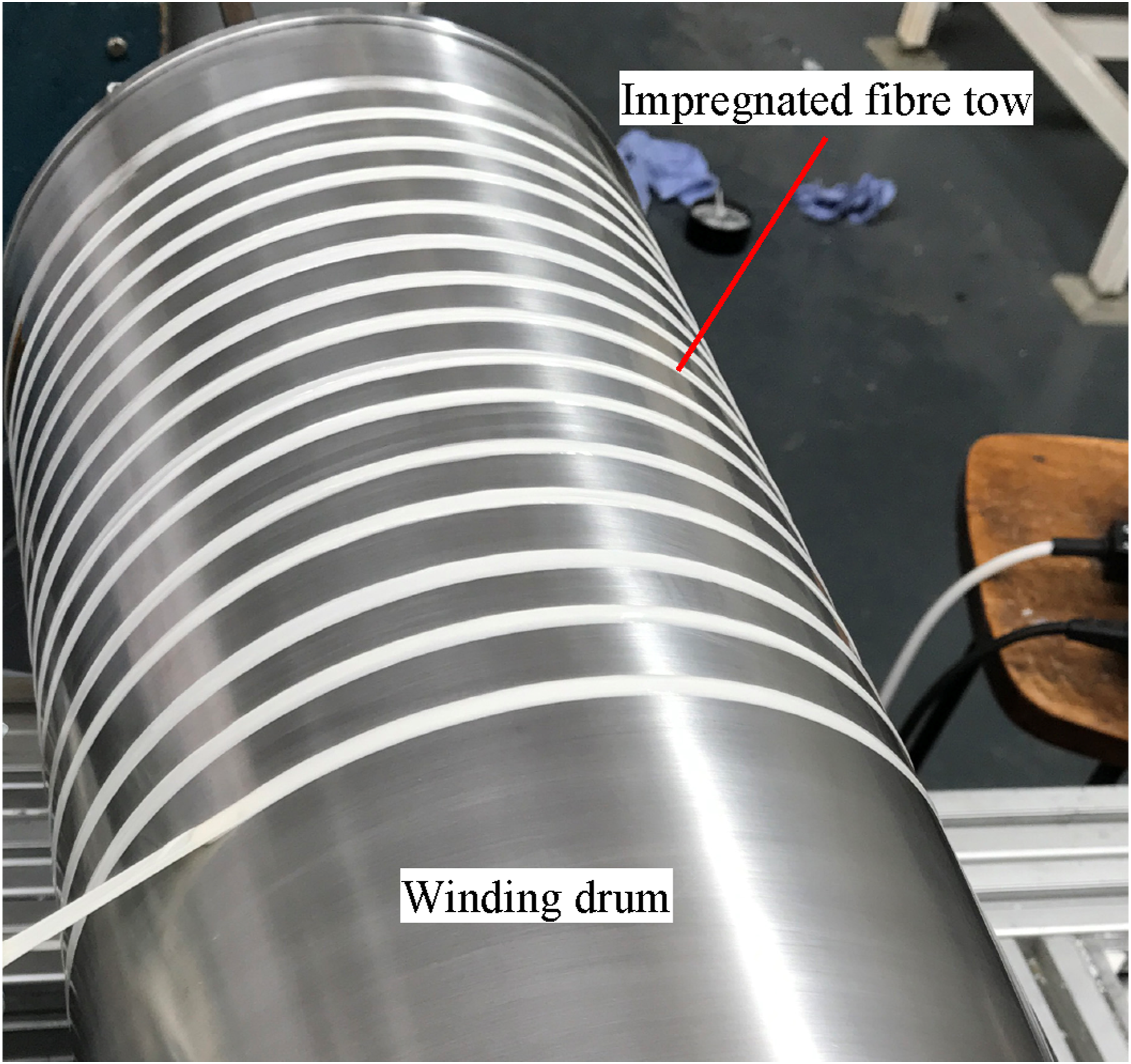
Results and discussion
This section compares results from tests on polymer–carrier experiments, prepreg rig settings, and resin pick-up. The aim is to investigate the consistency of production in terms of the amount of polymer powder collected by the fibre tow.
Winding speed and fibre tension
Winding speed is effectively varied from 20 to 100 %, with an interval of 10 %. This is equivalent to 0.6 to 11.9 m/min as previously listed in Table 2. Fibre tension is initially kept constant and is set to Setting 1 (0.8 N), as shown in Table 1. Here, 30 % (1.6 m/min) and 40 % (2.9 m/min) speeds were tested. It was found that such slow speeds would result in some major problems. Firstly, the time it takes for the full transverse around the winding drum is significant. For the winding speed of 1.6 m/min, it approximately took 50 min for the linear actuator to complete the transverse run for a full winding. This time was reduced markedly when 2.9 m/min setting was used. However, with both settings being relatively slow, other problems emerged. As can be seen in Figure 6, when these slow speeds are used for winding, the slurry starts accumulating at the bottom part of the drum and subsequently drips off the winding drum. This is not ideal as considerable amount of resin slurry would be wasted. Also, the free run of slurry droplets would result in an uneven distribution of slurry and change the amount of resin dispersed on the prepreg and consequently, alter the consistency of the production. Polymer slurry dripping from winding drum for slow winding speeds.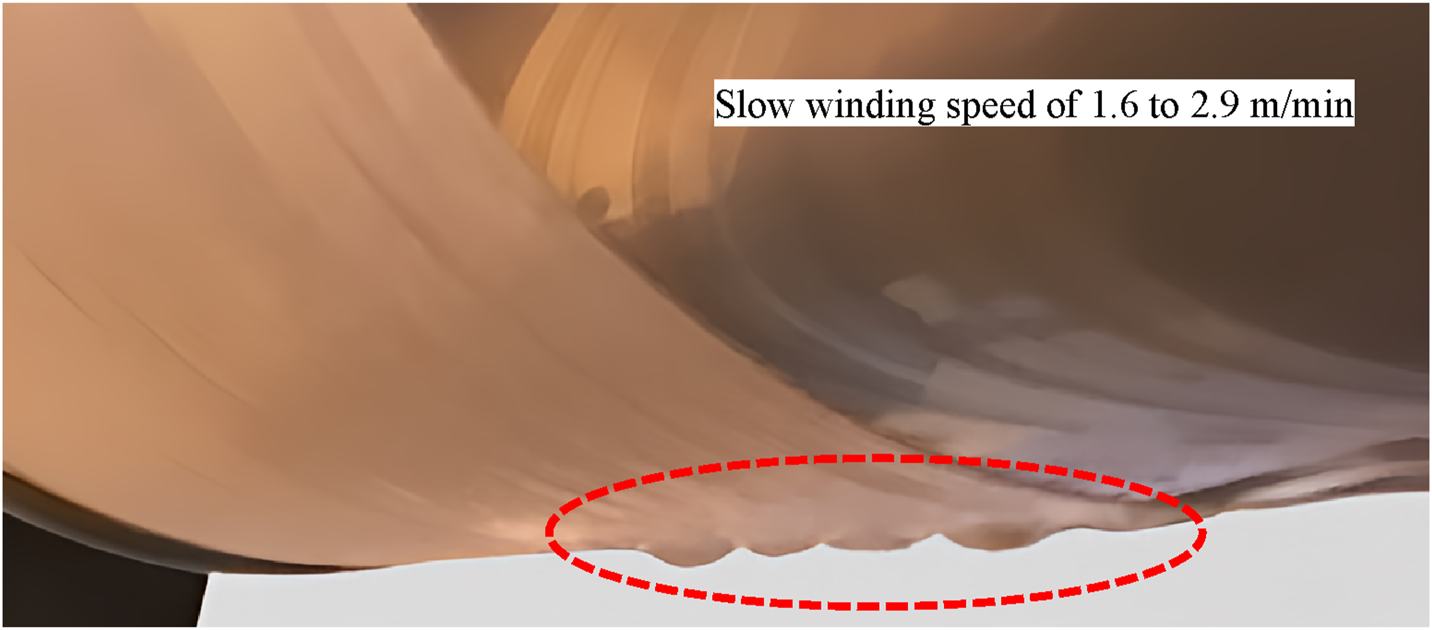
Another problem identified while using slow winding speeds was the heavy drip of the slurry from the spreading rollers as illustrated in Figure 7. Although this phenomenon is beneficial in terms of discarding the excess resin off the rollers, the large amount of PAEK slurry unloaded due to the slow speed of the fibre tow would result in not enough resin being deposited on the fibre filaments. When dried, the wound prepreg had obvious signs of exposed fibres due to lack of sufficient resin. Polymer slurry dripping from spreading rollers for slow winding speeds.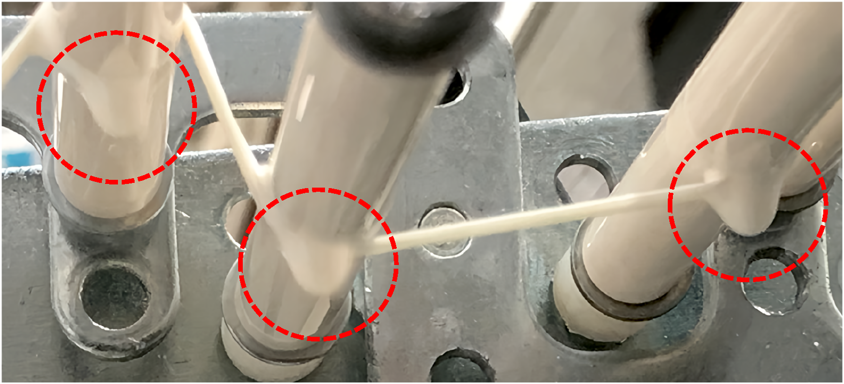
Faster winding speeds were also tested. It was found that for the speed of 70 % (7.4 m/min) or more, the aforementioned dripping issues were addressed, however, numerous other problems surfaced. For such the speed, the amount of resin picked up by the fibre tow is significantly increased and the excessive slurry does not find enough time to drop back to the resin bath. Figure 8 illustrates an example that the speed of 70 % (7.4 m/min) is chosen. From Figure 8(a), it is evident that the slurry starts running free on the drum when it is turning with high speeds. This could result in high tolerances in the prepreg thickness values and an irregular surface finish. Figure 8(b) demonstrates the heavy resin pick-up after the winding is complete with resin moving freely on the outer surface of the prepreg. Once dried, polymer powder was observed agglomerating in certain parts of the prepreg as per Figure 8(c), creating a rough and inconsistent prepreg surface. Such situation is not desirable as the final prepreg material would have high thickness variations and consequently, the laminated composites would have resin rich areas that significantly weakens its mechanical properties. Winding problems at high winding speeds: (a) free slurry run on the drum, (b) heavy resin pick-up and (c) irregular prepreg surface after drying.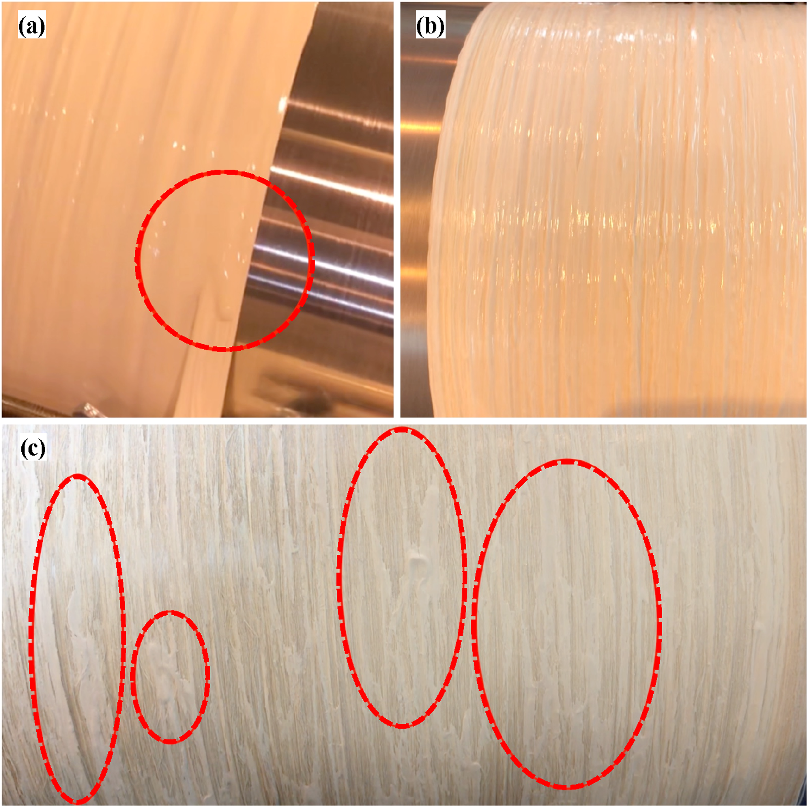
Higher winding speeds of 90 % (10.4 m/min) and 100 % (11.9 m/min) fosters additional drawbacks. As mentioned before, heavy resin pick-up by the fibre is observed during high-speed winding. This is followed up by excessive build-up of polymer powder on the spreading rollers as seen in Figure 9. Resin agglomeration around rollers reduces fibre spread effectiveness and increases breakage. Higher speeds of 80 % or more decrease fibre spread and hinder impregnated fibre tow width increase. Resin accumulation causes stress, leading to breakage and excessive abrasion during tow passage through resin and rollers. S2-glass fibre breakage causes tangling around the rollers and rough surfaces. The abrasive and brittle S2-glass fibre damages the tow passing on another glass fibre surface created by tangling around the rollers, leading to additional breakage. Polymer agglomeration around the rollers due to high winding speeds.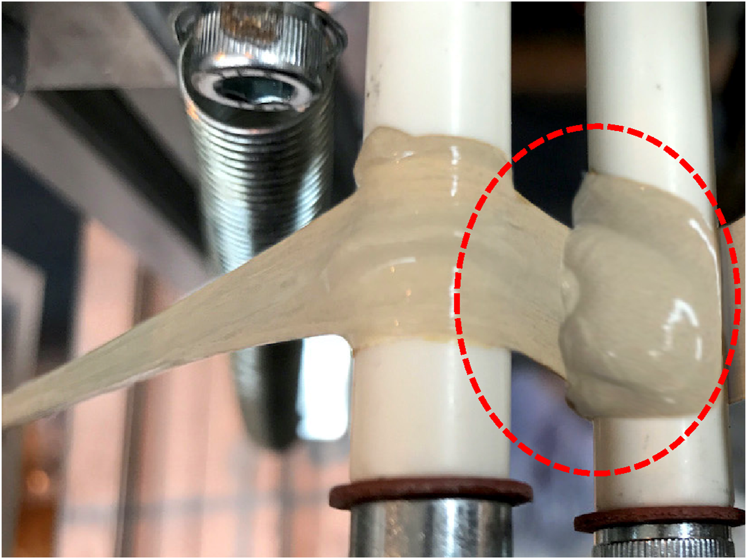
Previous findings indicate that very low or high speeds are not ideal. Therefore, winding speeds of 50 % (4.2 m/min) to 60 % (5.7 m/min) were tested as the optimum mean. It is evident from Figure 10 that many of the problems associated with low- and high-speed windings are addressed when moderate speed setting is utilised. It was concluded that winding speeds between 50 % (4.2 m/min) to 60 % (5.7 m/min) are the most beneficiary. Therefore, it was decided to choose the winding speed of 55 % (4.9 m/min) as the ideal speed for the winding process, for further tests, and for the manufacturing of prepregs. However, all previous tests were conducted when the initial tensioning force is set to Setting 1 (0.8 N). One major problem that was discovered during the observations was the presence of considerable fibre waviness. As illustrated in Figure 10, the impregnated fibre tow displays waviness when wound on the drum. The curves in reinforcing fibres significantly affect mechanical performance of the prepreg and laminated composite, as straight fibres have less crimp and function better. For this reason, other fibre tension settings were tested as well. Fibre waviness observed during medium speeds and low-tension settings.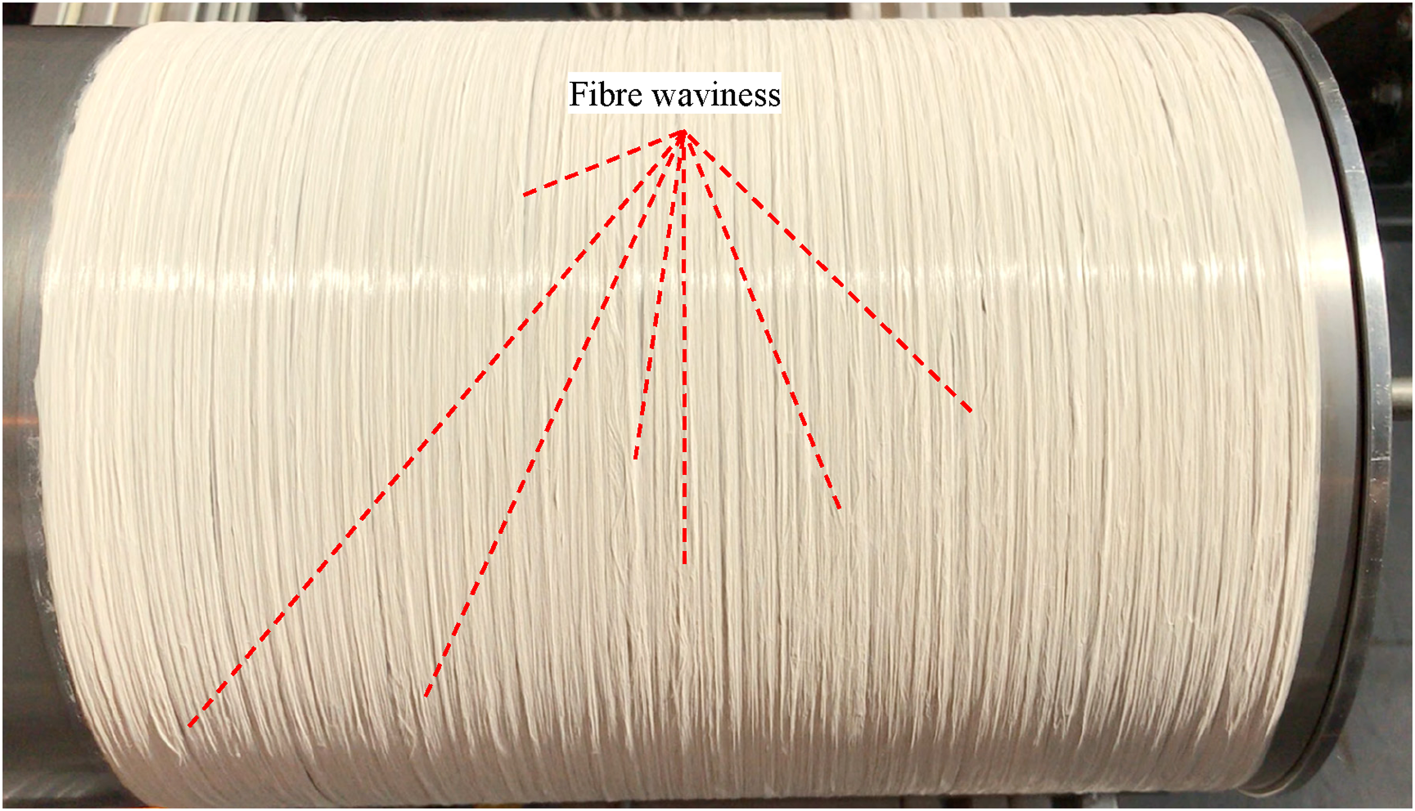
Figure 11 compares the quality of the winding when different tension settings are utilised. As discussed before, the fibre waviness, when the fibre tension setting is set to Setting 1 (0.8 N), can be attributed to the low initial tensioning force on the fibre tow and therefore, the formation of curves on the impregnated S2-glass fibres. By adjusting the initial tensioning force to Setting 2 (1.3 N), the fibre waviness issue is tackled and the prepreg quality improves. Fibre breakage is also kept to a minimum with no obvious signs of resin agglomeration on the rollers or resin rich areas on the prepreg. When higher fibre tension settings, such as that Setting 3 (2.3 N) or more are used, the fibre tow tends to wind up straight as expected. However, signs of fibre breakage were spotted on the material when the wound prepreg is dried. Increase in the initial fibre tension generates high pulling forces on the fibre roving. As the fibre passes through the rollers, this tension builds up and results in breaking of filaments. As filaments start to break (and tangle on the rollers), polymer powder also gathers on the rollers, which initiates further fibre breakage. Broken filaments ultimately affect the mechanical properties of the composite such as the tensile strength and modulus of elasticity. It was therefore concluded that the initial tension setting on the package holder should be adjusted in a fashion to aid directing the fibre tow through different guides on the prepreg rig. Tension force should be just sufficient to hold the reinforcing fibre straight and excessive tension should be avoided. It was decided to choose Setting 2 as the ideal tension for the winding process, for further tests, and for manufacturing prepregs. The effect of fibre tension setting on the quality of fibre winding.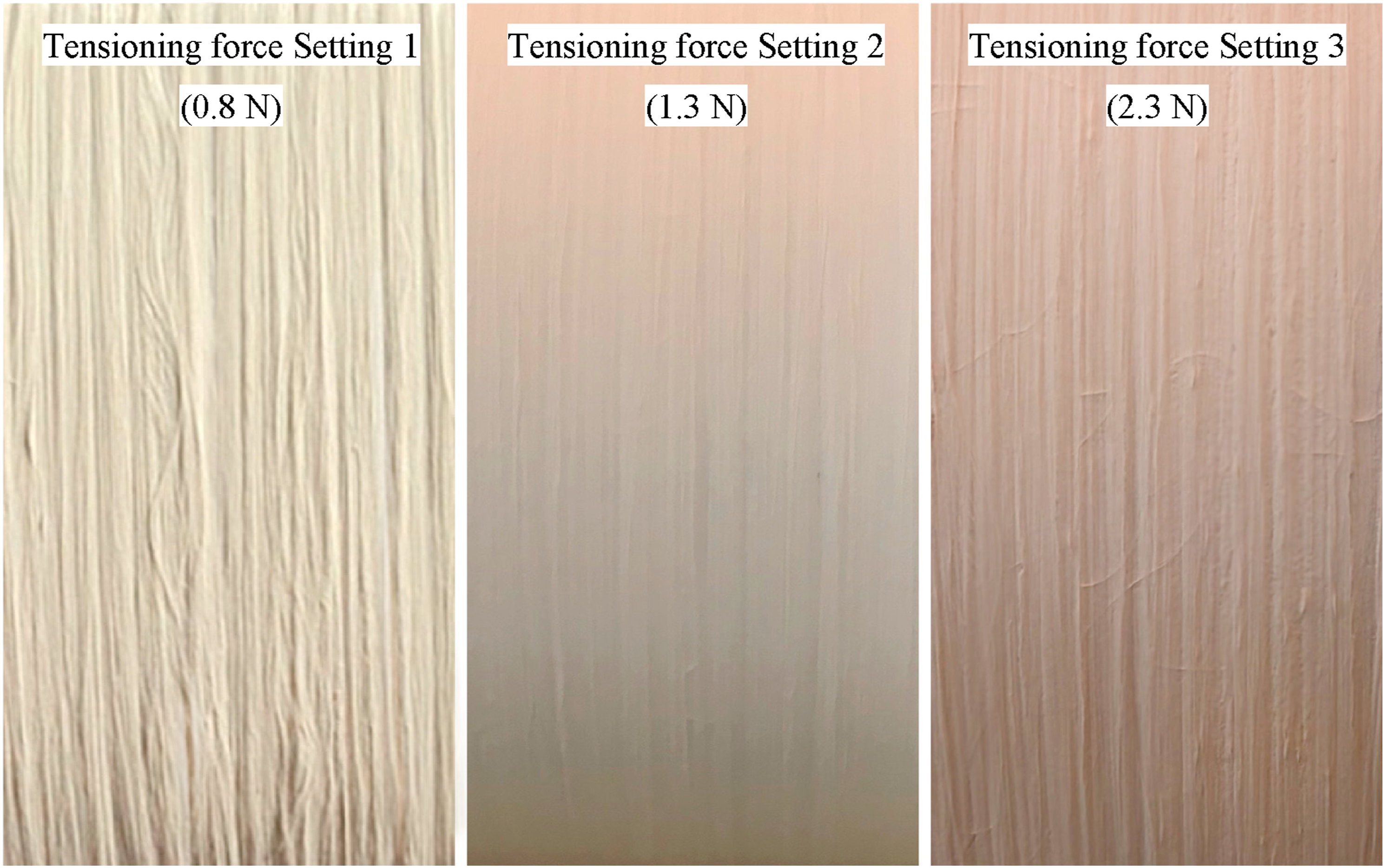
Resin pick-up test results
Resin pick-up test was conducted to verify the consistency of the winding process from when the fibre tow picks up the polymer slurry and is wound on the drum. The goal would be to identify whether the fibre bundle collects a constant amount of resin. Here, only the polymer–carrier ratio is changed, and other variables are kept constant. Figure 12 exhibits the results recorded from the four polymer–carrier ratios that were tested. It is indicative from the figure that 10 and 20 wt% slurry provides a very consistent collection of polymer slurry throughout the impregnation process. For 10 wt% slurry, the impregnated fibre mass tolerance is within ±0.05 g with a standard deviation of 0.03. A similar trend was also observed for 20 wt%, recording a standard deviation of 0.03 as well. This fashion is slightly different in 30 wt% samples, as can be seen in the figure, which has a slight downward trend. The reason of this descending order lies on the fact that for 30 and 40 wt% polymer slurry, resin agglomeration was observed on the spreading rollers, consequently increasing the fibre tension and breaking fibre filaments. Fuzz was created on the rollers, with filaments starting to tangle around the rollers. Ultimately, what emerges next is less and less fibre filament being wound on the drum and the impregnated fibre bundle starts losing mass. In the extreme cases, fibre bundle is cut off due to the high fibre loss and high tension on fibre. Consistency checks of the impregnation process by resin pick-up test.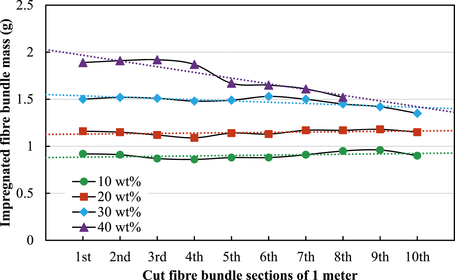
This circumstance is even more obvious in 40 wt% slurry trend line, as evident in Figure 13, heavy agglomeration is occurred when these resin systems are experimented. As shown in Figure 13(a), resin agglomeration is observed throughout the winding process when 30 wt% resin is used. It is clear from the figure that the first two rollers accumulate the most amount of slurry as expected, since polymer powder is squeezed off the fibre bundle as it travels through the impregnation rollers. Figures 13(b)–(d) demonstrate the same trend for 40 wt% resin system, however, in a more aggressive fashion. After only 3 revolutions of the drum, a heavy slurry agglomeration is observed. Fibre entanglement around the rollers and creation of fuzz leads to fabrication of a rough surface on the rollers and causes further resin gathering and filaments splitting. After approximately 13 revolutions (8 m of winding), resin agglomeration and fibre tension become so severe that majority of fibre filaments are broken. Hence, the winding is stopped after around 13 revolutions for the 40 wt% resin setting. Resin agglomeration on spreading rollers: (a) 30 wt% slurry system and (b–d) 40 wt% slurry system.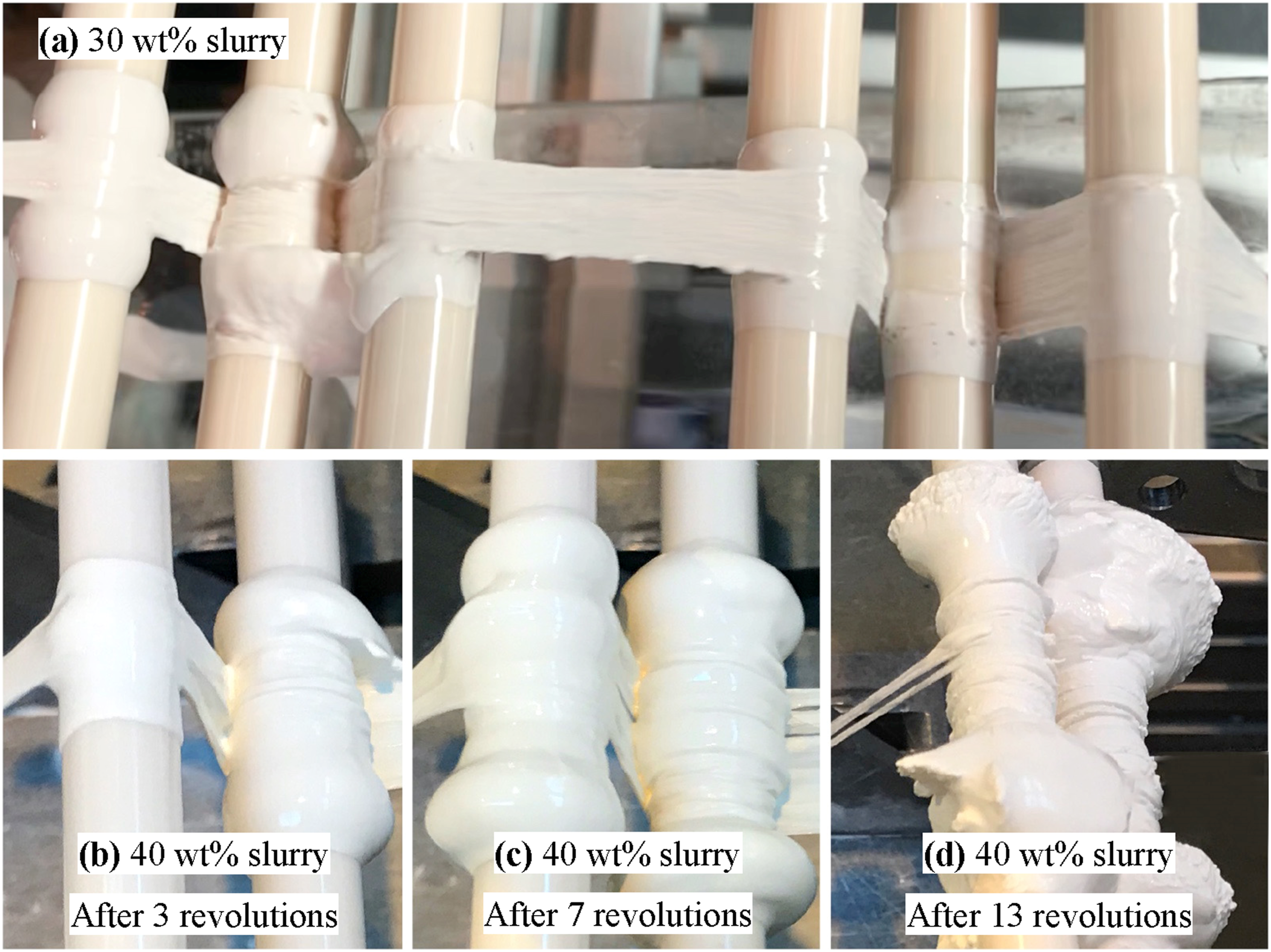
The agglomeration of polymer powder around the rollers during the aqueous powder impregnation can be attributed to several factors. The high concentration of polymer in the slurry can lead to the formation of large polymer particle accumulation that are difficult to disperse uniformly in the solution (as discussed in the next section). As a result, these particles tend to agglomerate and settle around the rollers. Furthermore, it is imperative to consider the saturation point of the fibre material during the impregnation process, as an over-saturated material may hinder its ability to absorb additional polymer powder. As the fibre tow travels through the impregnation rollers, any excess resin is extruded from the fibre material. In the case of high concentration systems (30 and 40 wt%), the slurry encounters difficulty disengaging from the rollers due to its increased viscosity (compared to 10 and 20 wt% slurries). This, in turn, leads to the undesired outcome of powder agglomeration around the rollers. As evident from Figure 12, the reintegration of excess slurry into the resin bath for 10 and 20 wt% systems is deemed acceptable, as it demonstrated no discernible impact on the resin pick-up by the fibre.
Grade 933-AA-750 S2-glass has a linear density of 675 g/1000m (TEX) and therefore, a 1-m-long section of the dry fibre bundle would have a mass of approximately 0.68 g, which was also confirmed by the in-house experiment. By obtaining the mass of the polymer picked up by the fibre, and taking into account the density of the fibre (2.47 g/cm3) and polymer (1.28 g/cm3), fibre volume fraction in the impregnated fibre bundle was calculated for different slurry systems, as shown in Figure 14. In average, 1 m of impregnated S2-glass with 10 wt% slurry would pick up approximately 0.22 g of polymer powder, which yields a 61.1 % fibre volume sample. The decrease in fibre volume fraction seems having a relatively linear trend as the polymer concentration increases in the slurry; however, there is a decline in gradient between 30 and 40 wt% settings. It can be presumed that the higher polymer–carrier ratios (if practically possible to implement) will have a less effect on the amount of polymer powder picked-up by the fibre. Fibre volume fraction of the impregnated fibre for different slurry systems.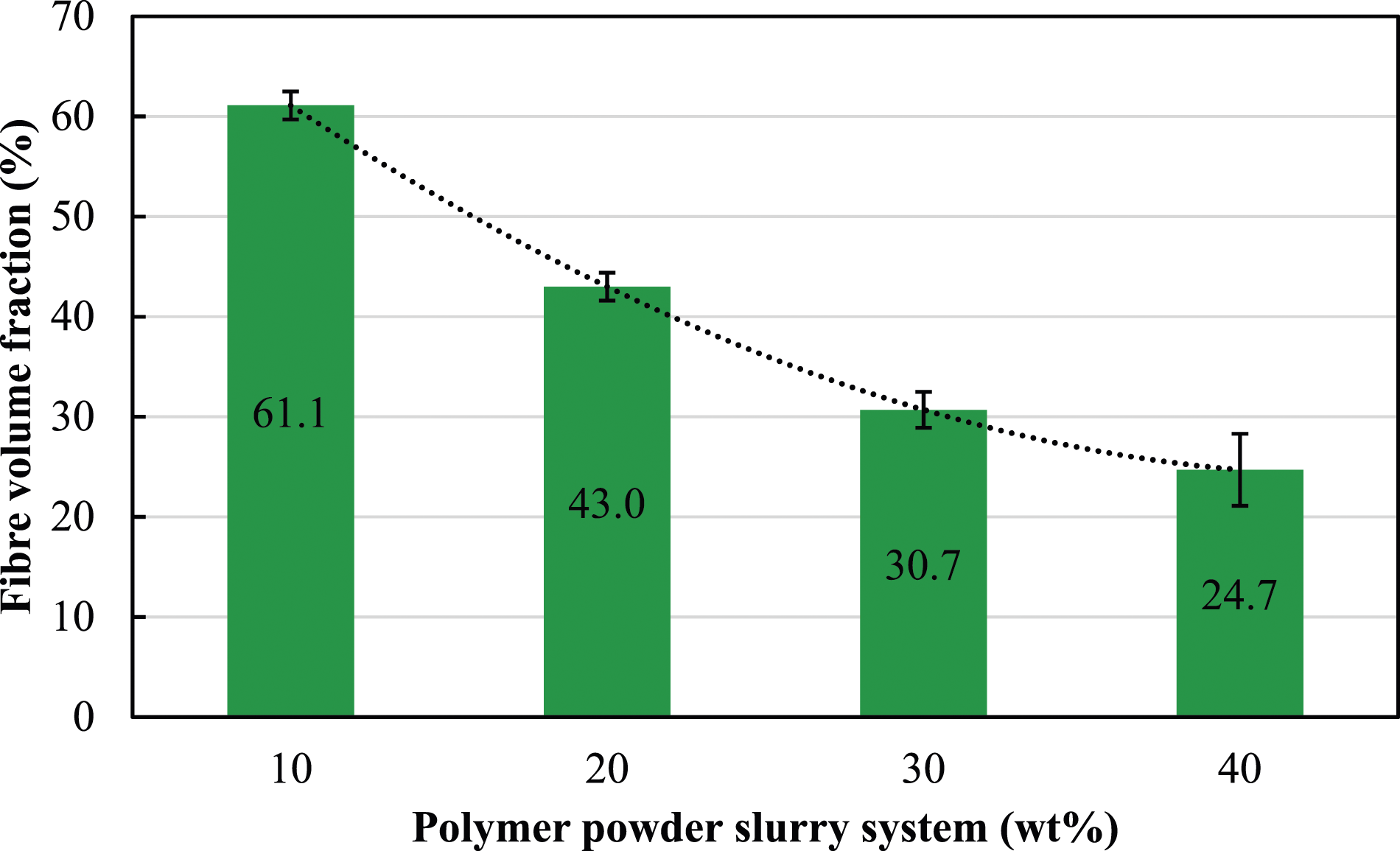
It was concluded that 40 wt% polymer–carrier ratio is too viscous for prepreg manufacture and would cause numerous problems as previously mentioned. This resin setting was therefore withdrawn from any further experimentation. Although the 30 wt% polymer–carrier ratio was also found problematic with regards to resin agglomeration, it was realised that with an effort to slightly remove the accumulated resin manually from the rollers, one can proceed with the winding process for half the length of the drum and thus, manufacturing of the prepreg is just made possible.
Turbidity measurements
Figure 15 illustrates a visual macroscopic fingerprint of 10, 20, and 30 wt% slurry samples over a 120-min period. Here, two synchronous optical sensors receive, respectively, light transmitted (T) through the sample, and light backscattered (BS) by the sample. The captured data provides the transmitted and backscattered light flux in percentage relative to the standard suspension of monodisperse spheres and silicone oil, as a function of the sample height (in mm). Usually, backscattering data is used to analyse opaque and concentrated dispersions, which is the case in this study. Visual stability of samples over the height of filled vials after 2 hours for: (a) 10 wt%, (b) 20 wt%, and (c) 30 wt% polymer slurries.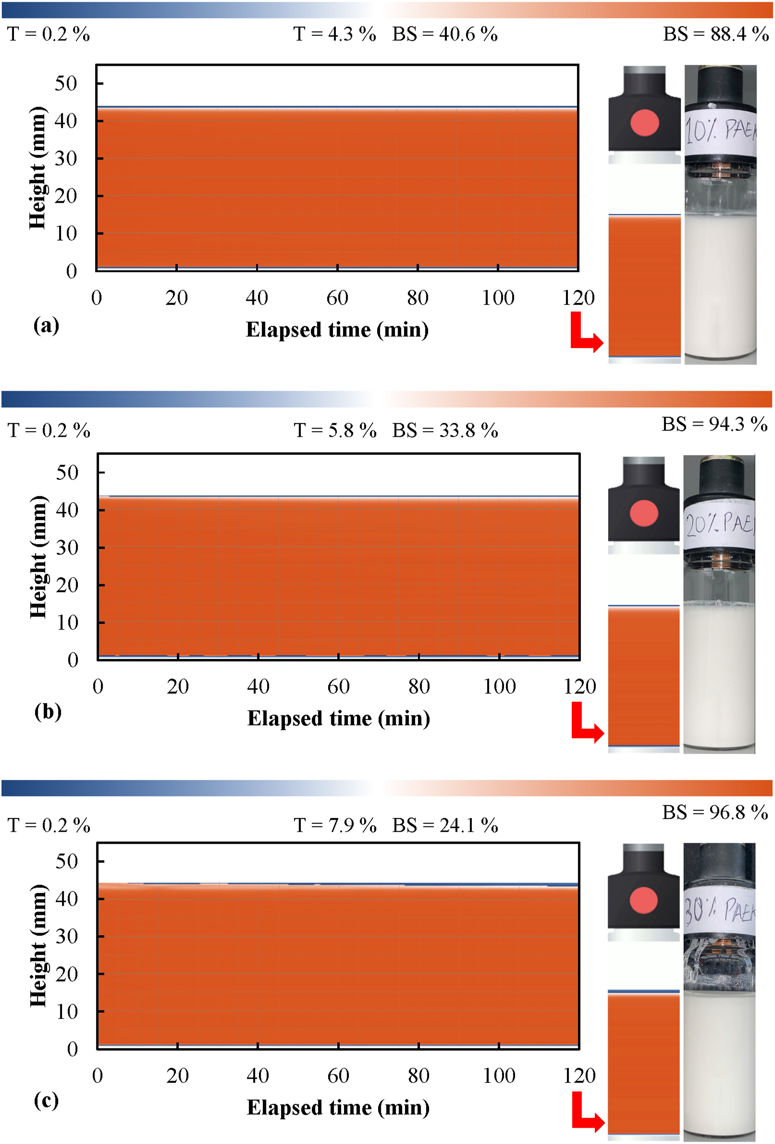
The mean BS value measured during the first scan of the middle part of the vials (14 to 29 mm) for 10, 20, and 30 wt% sample were 88.1, 93.8, and 95.1 %, respectively. This is a direct indication that slurries with higher polymer concentration would have a higher BS value. This is typical as higher particle concentrations will result in more light being backscattered.
Colloidal systems commonly experience two types of instabilities, namely particle migration and size increase. Changes in particle concentration locally and globally will affect the measured T or BS level. Turbidity profiles can also be divided into three parts: bottom, middle, and top, where migration phenomena occur at the top and bottom and particle size changes in the middle. It is observed from Figure 15 that all three samples have a relatively good colloidal stability for a duration of 120 min. The variations in BS of the middle part of the samples for the last cycle (after 120 min), compared to the initial middle scan for all three samples, were observed to be less than 1 %. This therefore demonstrates no significant evidence of change in particle sizes, that is, particle flocculation. Sedimentation is encountered when the density of the dispersed phase is greater than the density of the continuous phase. By studying the variation in the concentration of the polymer phase between the top and the bottom of the sample, sedimentation can be detected. As evident from Figure 15, there are traces of decrease in BS (and increase in T) at the top of the samples due to a decrease in the particle concentration. The mean BS values of the top part of the samples in vial (35 to 43 mm) for the last cycle (after 120 min), compared to the first scan, are decreased by 1.8, 6.0, and 12.9 % for 10, 20, and 30 wt% samples, respectively. These values suggest that 10 wt% suspensions are quite stable for a duration of 120 min. Stability for 20 and 30 wt% samples are slightly lower compared to 10 wt% samples. Also, the phase separation (clarification) in 30 wt% samples are more obvious. This incident is expected as polymer concentration in 20 and 30 wt% samples are higher compared to 10 wt% samples and consequently, results in a faster migration of the particles to the bottom of the vial.
Figure 16 shows delta BS traces of the final scan for 10, 20, and 30 w% samples with respect to the height of the vial. For a better visualisation of the results and to amplify the variations, delta values are implemented. Here, delta consists of subtracting the reference scan (by default the first one) from the other scans and using this reference scan as a blank value. The graph shows the changes in the BS values for the full height of the vials. All three samples show a relatively steady BS throughout the middle part of the vial. As expected, variations are only observed on the top and bottom of the samples. This time, small backscattering increases can be observed at the bottom of the samples due to an increase in the concentration of the polymer phase (sedimentation). However, these variations are insignificant compared to the clarification phase of all three samples. This behaviour suggests that the migration rate of the polymer particles in the top section of the vial is possibly faster than the migration rate in the bottom section. Another speculation could be that some or all ingredients of the carrier find their way to the top part of the vial (creaming) at a faster rate compared to the particle migration rate to the bottom. Delta backscattering values for the final turbidity scan of 10, 20, and 30 wt% slurry samples.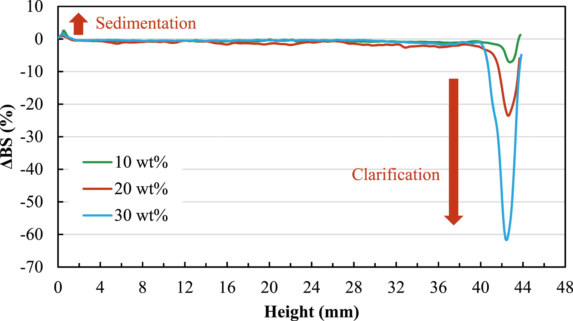
Given the obtained and analysed results so far, it can be suggested that the blend of dispersing and water-thickening agents inside the carrier can promote homogenous suspension of polymer particles in the slurry for prolonged periods without significant sedimentation and help preventing particle flocculation. Figure 17 shows the global destabilisation kinetics for the samples. The stability comparison of different formulations using only the raw T or BS signals can be difficult and requires advanced calculations. It is possible to monitor the destabilisation kinetics in the sample versus ageing time, using the Turbiscan Stability Index (TSI). TSI is a dimensionless value that is the result of summing all occurring destabilisation phenomena in the sample that can be measured by noticeable change of the BS or T signal intensity along the sample height. The higher the TSI value is, the lower the stability, as these signal variations are directly linked to any destabilisation in the sample. For the purpose of illustration, samples can be ranked and compared using the TSI scale, as per Table 3. As seen in the table, also in Figure 17, TSI values are associated with a colour that allows for a direct analysis of the samples. TSI detected during the experiment can be calculated as follows80,81 Global destabilisation kinetics versus the ageing time for different samples. Interpretation of different levels of the TSI scale.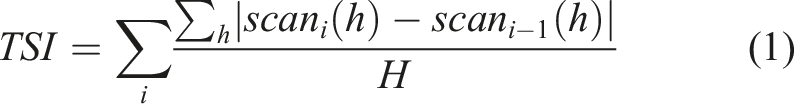
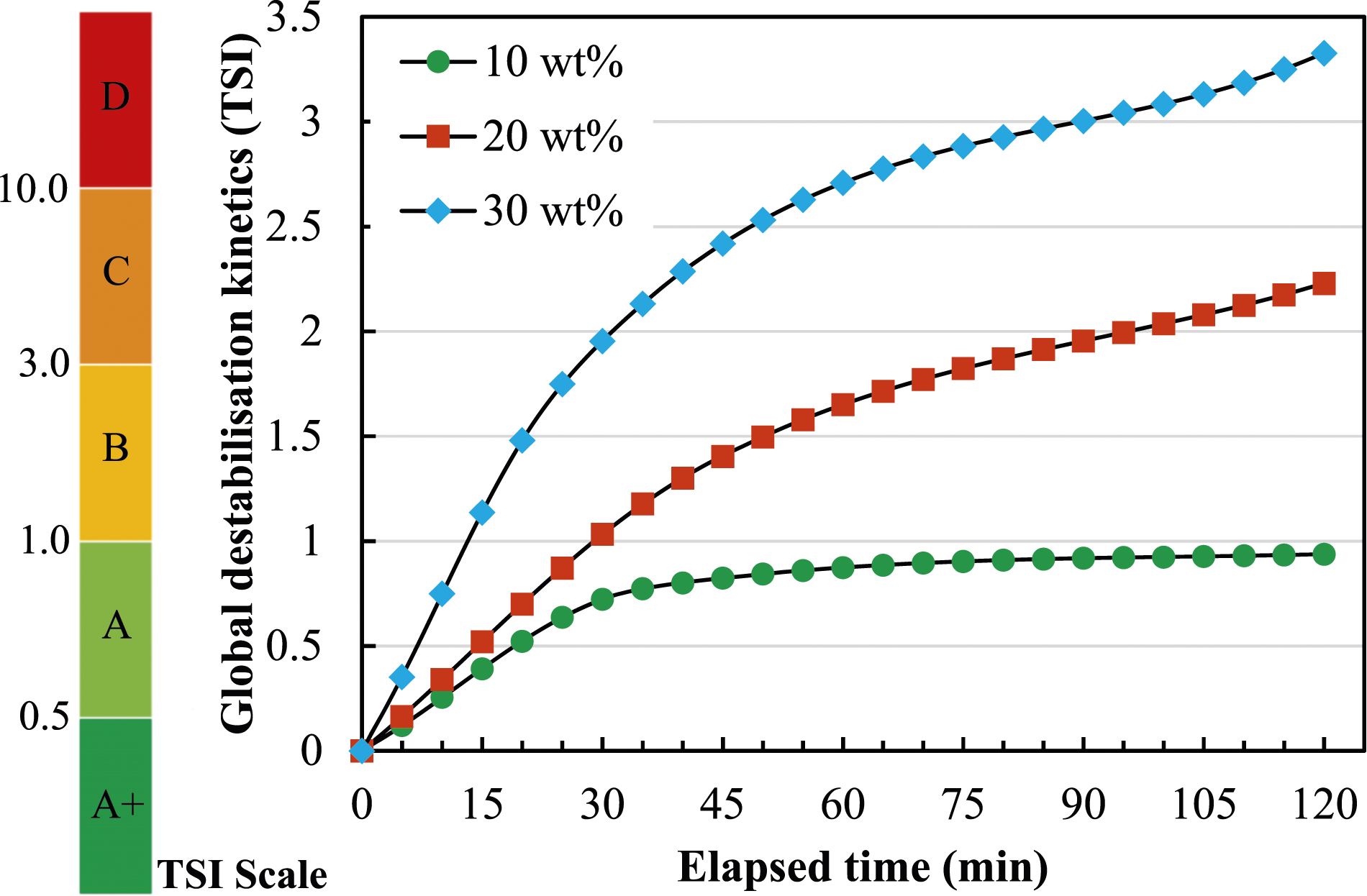
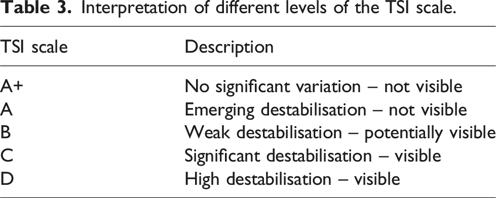
Figure 17 shows that for 120 min of sample ageing, the TSI values for 10 wt% PAEK samples show a steady grow for 30 min, and then slight increases until the TSI value reaches just below 1. Values between 0.5 and 1 indicate a visually good suspension (Band A). Destabilisations are detected but are at the very early stages. In the A-ranking, no visual destabilisations are observed. Here, 20 and 30 wt% samples have a higher initial growth slope compared to 10 wt% samples and they stand at 2.23 and 3.33 after 120 min, respectively. This would place 20 wt% samples in category B and 30 wt% samples in category C. In band B, destabilisations remain non-visual in most cases; however, important destabilisations corresponding to large sedimentation/creaming or particle size variation can be attributed to band C. All said, analysing the TSI data for an ageing time of 30 min show that all the values for 10, 20, and 30 wt% samples remain under 2, with 20 and 10 wt% even being 1 and under. Although the turbidity test was run for 120 min, the captured data for 30 min of elapsed time is a more pragmatic time scale for the impregnation process of the prepreg manufacture. This clearly indicates that for a duration of 30 min, no external stirring would be necessary inside the resin bath for agitating PAEK particles, and the slurry concentration remains constant during the winding for a consistent prepreg production.
Thermogravimetric analysis
TGA analysis was carried out on neat L2O carrier and the 10, 20, and 30 wt% slurry systems. L2O is a water-based and non-hazardous dispersion system that allows polymer powder to be suspended in a slurry. It contains a blend of dispersing and water-thickening agents that promote homogenous suspension of PAEK particles in the slurry for prolonged periods without settling and helps prevent particles from clumping up. As evident from Figure 18, the liquid carrier loses on average 89.06 % of its mass when heated from room temperature to 100°C. This indicates that the carrier is indeed comprised of mostly watery, and possibly other volatile components, which start leaving the carrier as soon as the heating process starts. Generally, the rate of change in the mass loss slows down at around 90°C, with the carrier losing mass gradually as the temperature increases. The residual mass of the carrier was recorded as 5.52 and 3.21 % at elevated temperatures of 200 and 300°C, respectively. The decomposition of other components in the blend continues until virtually all the ingredients are carbonated. On average, the residual mass of the carrier was recorded as 1.85 % at 400°C. Thermogravimetric analysis of the liquid carrier.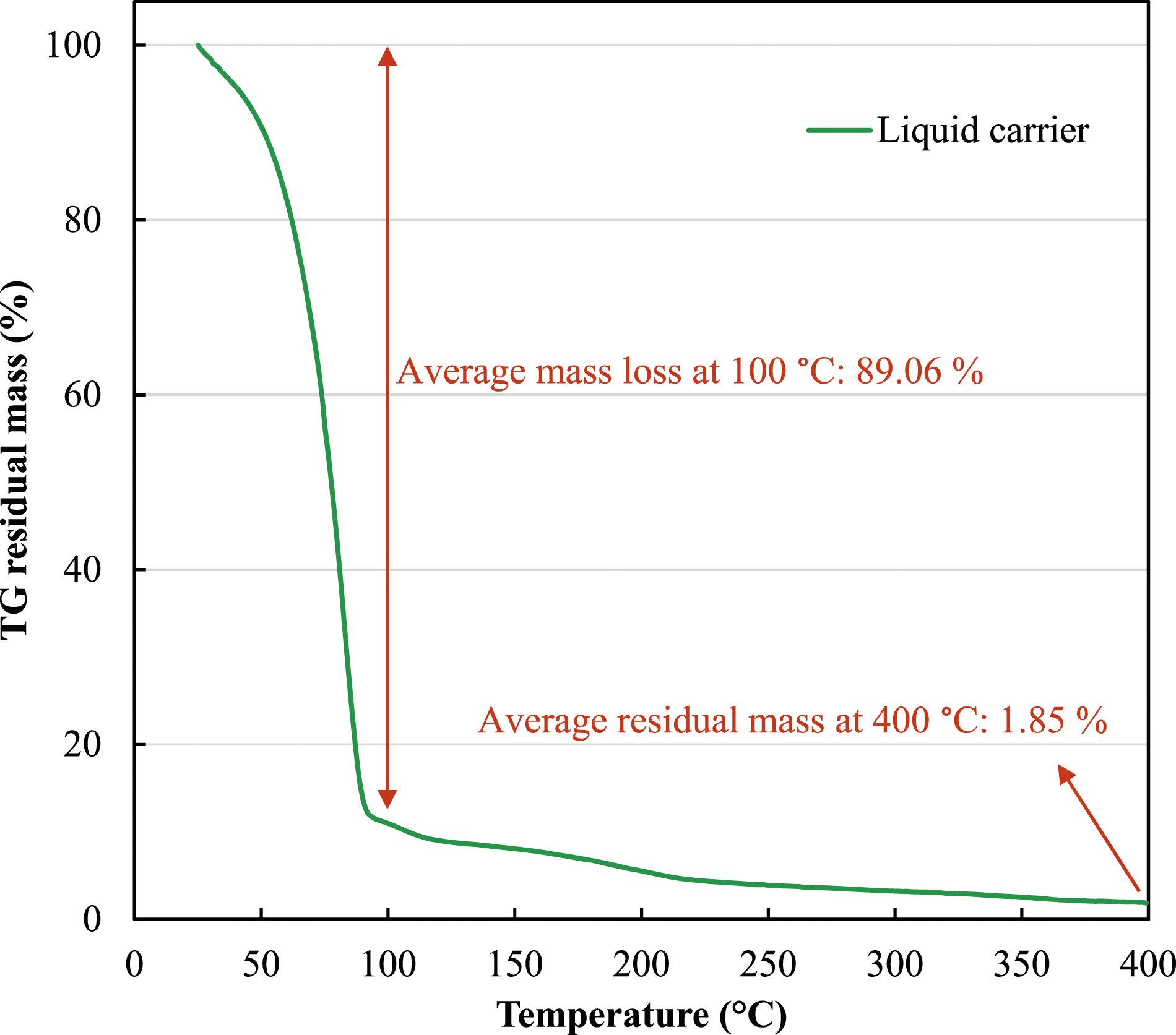
Figure 19 compares the residual mass of the liquid carrier as a stand-alone sample, and in the 10, 20, and 30 wt% slurry systems. For the slurry systems, the residual mass of the carrier left in the polymer was calculated by subtracting the proportional mass of the PAEK employed to prepare the slurry, from the measured mass of the residual PAEK after heating to 400°C. It is worth noting that no loss in PAEK mass was observed at this temperature as its thermal decomposition usually begins at temperatures exceeding 500°C. It is evident from the figure that the liquid carrier leaves very minimal residues at the typical consolidation temperature of the PAEK for manufacturing thermoplastic composites. The higher residual mass of the liquid carrier in 10 wt% system in comparison to 20 and 30 wt% can directly be attributed to the higher mass ratio of the carrier in the slurry system, subsequently yielding a higher residual in the sample. Generally, in all three systems, the basic PAEK is all that remains after heat melting to 400°C and almost all the carrier leaves the polymer. Resinous ingredients in the carrier provide great initial bond between PAEK particles and glass fibre filaments, holding the particles firmly on the fibres even after the water base is dried and evaporated. Heat melting the PAEK subsequently results in permanent bond on reinforcing fibres for manufacturing thermoplastic prepregs. The residual mass of the liquid carrier in 10, 20, and 30 wt% slurry systems.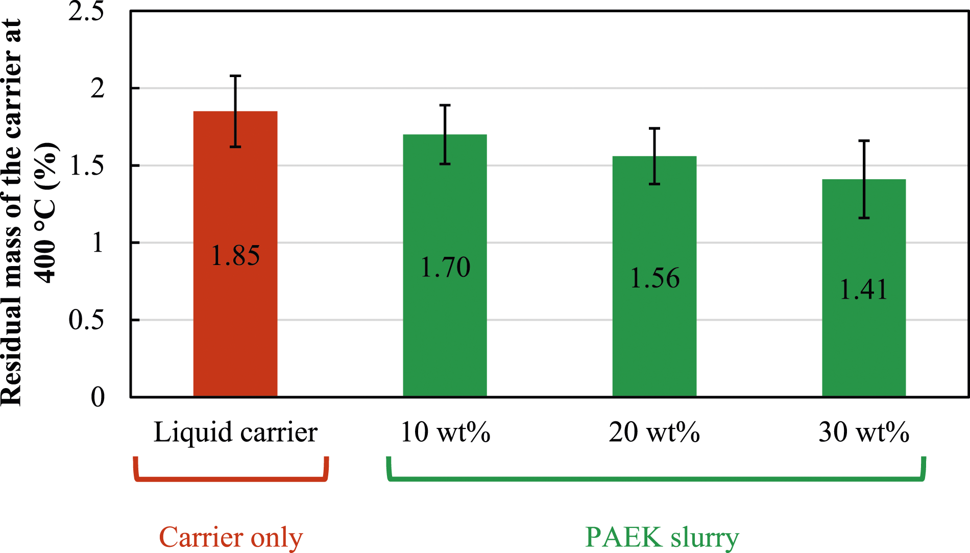
Cross-sectional micrographs
Transverse and longitudinal cross-sections of prepreg plies were observed to understand the polymer impregnation rate. Micrographs of cross-sections reveal the polymer particle infusion rate and fibre/matrix distribution homogeneity. Figure 20 displays micrographs of three cut and stacked specimens from random parts of three prepreg plies with slurry ratios of 10, 20, and 30 wt%, respectively. As can be observed from the figure, air bubbles are present in each of the three categories. The phenomenon of small void formations within the thermoplastic prepreg is primarily attributed to the polymer impregnation method employed, which heavily relies on the spreading rollers. The impregnation process plays a pivotal role in prepreg formation, with spreading rollers being crucial for facilitating resin distribution onto the fibres. However, the exclusive reliance on spreading rollers poses challenges, potentially resulting in areas with inadequate impregnation. Insufficient compaction during this stage becomes particularly critical, as the wet fibre tow lacks supplementary compression when wound around the drum. The absence of supplementary compaction before or after the fibre is wound onto the drum emerges as a critical factor leading to the formation of small void spaces within the prepreg. Lack of further pressure allows for the persistence of air pockets and voids between adjacent fibres. The observed voids in the micrographs are a consequence of incomplete resin impregnation and the insufficient compaction during the winding process. The void content is slightly elevated in 30 wt% prepregs, potentially attributable to increased slurry viscosity, which may impede impregnation in comparison to 10 and 20 wt% slurries. Certain microcracks and fractures observed in the prepreg micrographs can be attributed to possible mishandling of the prepreg plies when cut, or any damages tolerated during the polishing process. The bottom side, having come into contact with the winding drum, results in a smoother surface, ultimately leading to a straighter appearance. Cross-sectional micrographs of prepreg plies with different slurry ratios.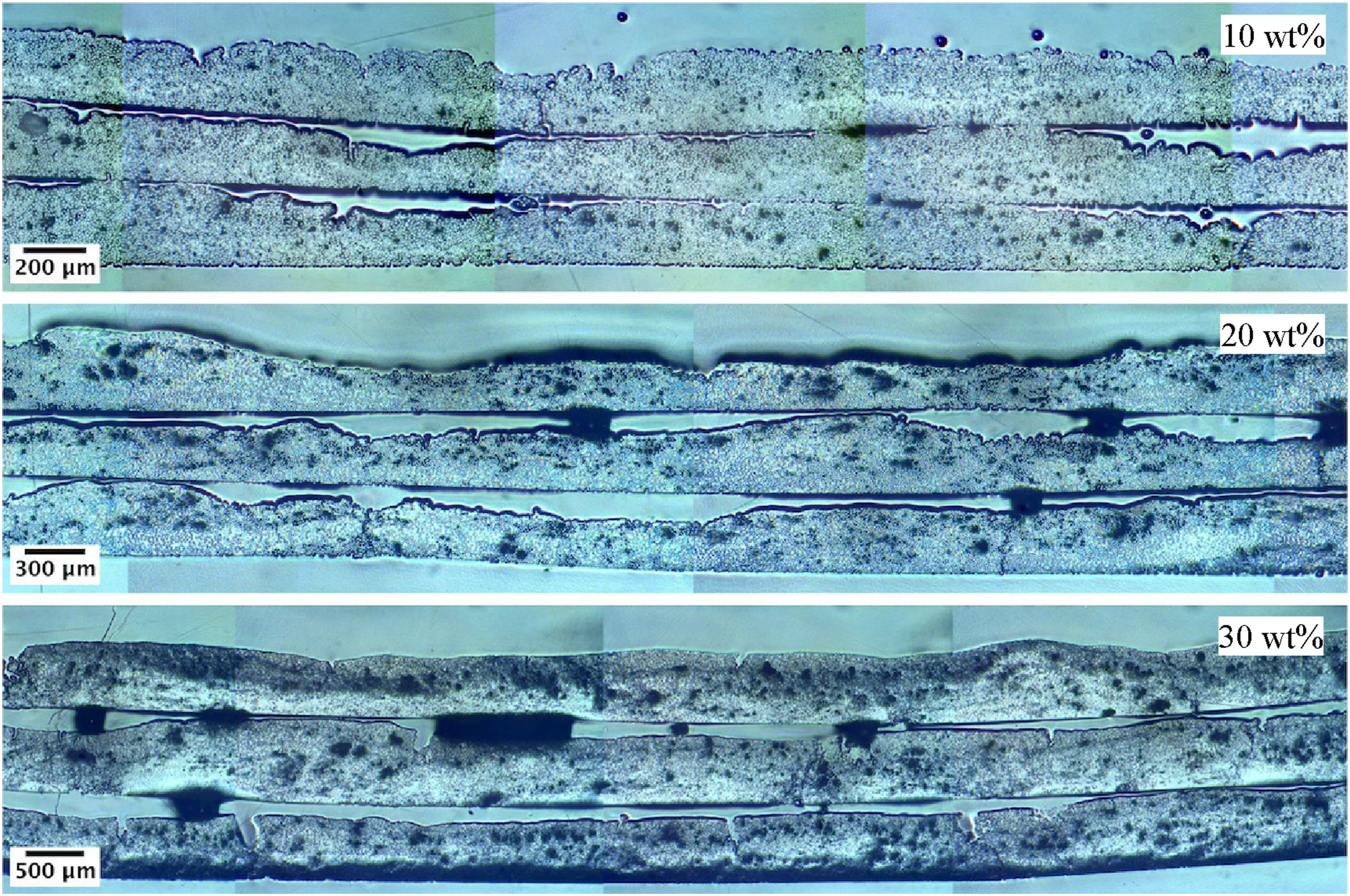
Despite the air bubbles in cross-sections, Figure 21 shows full polymer infusion between fibres. Longitudinal sections were also examined due to the limited nature of transverse views. All categories display strong powder infusion, a crucial factor for effectively impregnating fibres, especially in 10 wt% prepregs with very low polymer content. The figure illustrates the polymer reaching the centre of the glass fibre tow in 10 wt% prepregs, a trend also observed in 20 and 30 wt% prepregs. A closer examination reveals occasional higher polymer concentration on the top surface of the prepreg, possibly due to the movement of the resin slurry on the winding drum despite mitigation efforts. Tension from the winding drum further impacts the distribution, pushing polymer particles outward and leaving more fibres near the drum’s surface. Another observable factor in higher magnification micrographs is the presence of singular and agglomerated particles between the fibre filaments. This is a good indicator that the polymer particles are very well suspended in the liquid carrier without considerable agglomeration. Otherwise, such the high degree of powder impregnation was not practical. Finally, the 30 wt% prepregs show obvious resin rich areas in their cross-sections. The nature of such flaws in 30 wt% ratio prepregs is usually related to the problems associated with the prepreg manufacturing process such as agglomeration of resin on the spreading rollers and fibre waviness. Examining transverse and longitudinal prepreg cross-sections to assess the impregnation.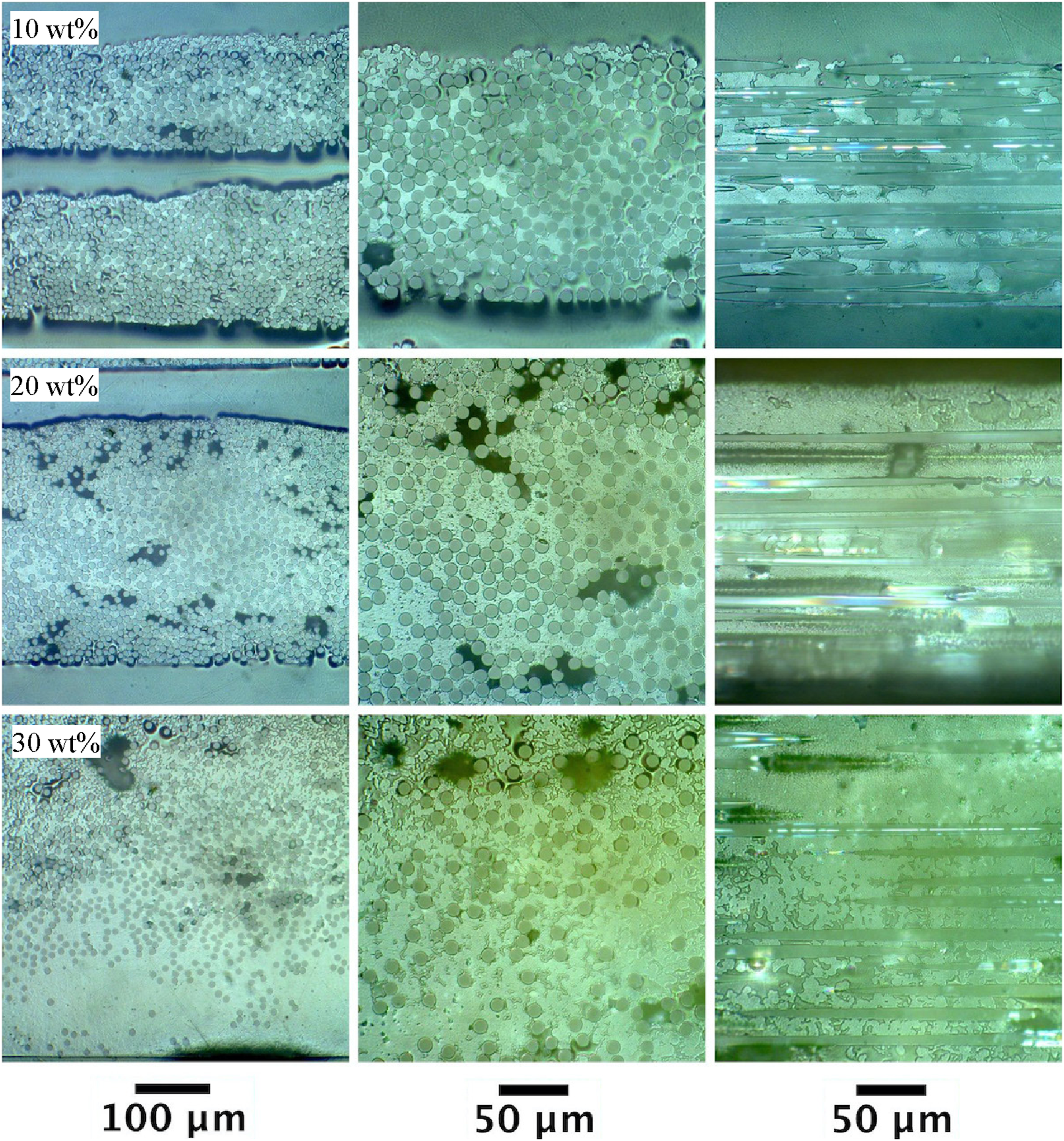
Conclusions
In this study, the concept of aqueous powder impregnation is discussed and practicality of an effective method of thermoplastic resin impregnation and subsequently thermoplastic prepreg production is investigated. A wet powder technology has been realised which can fulfil three main rig development requirements, namely suitability, cost, and scale. Here, a novel prepreg rig has been designed and manufactured for producing UD prepreg, as the most appealing material for producing performance composite materials. The design of the drum winding prepreg rig is based on the concept of filament winding, that is, impregnated fibres being wound on a drum to produce UD prepreg sheets. Different parts involved in the design and manufacture of the drum winding rig are produced and the function of each component is discussed. Common industrial practice of manufacturing UD prepreg would require multiple fibre bobbins, creels, guides, rollers, etc. and thus, requiring a substantial investment. The proposed thermoplastic prepreg manufacturing process based on drum winding is therefore found to be ideal for research and development purposes, due to the factors such as fast processing times and low running costs.
A number of tests have been carried out to understand and evaluate the effectiveness of the liquid carrier for prepreg production, and to study different variables such as the polymer–carrier ratio, tension of the fibre and winding speed. Experiments indicate that the proposed manufacturing method can potentially be used to produce UD thermoplastic prepreg. To facilitate prepreg production, the polymer–carrier ratio is chosen as the best option to control the volume of constituents. It has been found that the carrier is suitable for suspending and dispersing polymer particles. Tests on colloidal stability of slurries with different concentrations have shown that the carrier is capable of suspending 10 to 30 wt% polymer slurries, without serious sedimentations, at least for the duration of fibre winding. Thermal stability tests conducted on both the carrier and various polymer suspensions reveal that nearly all carrier ingredients leave the samples at consolidation temperatures of such composites. Medium winding speeds in the order of approximately 4.9 m/min have been found to give the best balance between processing speed and resin handling problems. Additionally, the tension exerted on the fibre bundle should be chosen in a way to provide only sufficient force for the fibre filaments not to deviate from their predefined path and to stay straight. Finally, it is realised that the prepreg rig is consistent in the amount of resin pick-up by the fibre bundle.
By carefully optimising the parameters for each specific configuration, successful production of S2-glass/PAEK prepregs has been achieved. Subsequently, these prepregs and their manufactured laminates can undergo comprehensive testing to assess the properties inherent in the samples. The comprehensive analysis of their physical and mechanical properties, as well as an in-depth examination of production line consistency, will be the focal points of our forthcoming study. This current work serves as a foundational feasibility study paving the way for the extensive discussions to follow.
Footnotes
Acknowledgments
The authors would like to acknowledge Victrex plc. (UK) for supplying the polymer powder sample.
Declaration of conflicting interests
The author(s) declared no potential conflicts of interest with respect to the research, authorship, and/or publication of this article.
Funding
The author(s) received no financial support for the research, authorship, and/or publication of this article.
Data Availability Statement
The raw/processed data required to reproduce these findings cannot be shared at this time as the data also forms part of an ongoing study. The data can be made available at a later date upon reasonable request by contacting the corresponding author.