
Abstract
Recent advancements in composite truss structures have achieved high structural efficiency by combining truss geometries and composite materials within scalable manufacturing processes. Filament winding-based approaches, such as the Wrapped Tow Reinforced (WrapToR) truss process, allow for simpler machine design compared to braiding or pultrusion but face limitations as production rates and truss beam lengths increase. We herein introduce WrapToR Trusstrusion, a manufacturing concept using coaxial winding heads to wrap multiple pre-wetted tows around continuously fed chord members, forming a complete wound truss structure in one pass. This eliminates the need for reciprocating motion and fixed mandrel lengths of conventional winding machines. We present the WrapToR Trusstrusion concept, the first prototype machine setup, and the numerical analysis and mechanical characterisation of produced specimens, aiming to assess the quality of the produced trusses. This innovative machine concept progresses towards high-throughput, continuous production of mechanically superior WrapToR truss beams while trading off process and geometry versatility for standardisation and production rate.
Keywords
Introduction
In the continuous drive for more efficient and lightweight structures, composite trusses have been shown to provide considerable advantages through the efficient use of material for maximal structural rigidity and strength. 1 Due to their intrinsic anisotropy and high stiffness along the fibre direction, composite materials are ideal for trusses. Nevertheless, although composite lattices have been around for almost half a century, their industrial uptake has been slow and limited to a few applications where the demand for structural performance justifies the high costs usually associated with their design and manufacture – as shown also by the examples cited later, most composite lattice applications are limited to the aeronautical and aerospace sectors.
Thanks to the non-linear scaling laws for flexural rigidity, beam-like truss structures offer substantial weight-saving possibilities, estimated at up to 80% with respect to equivalent steel structures and up to 20% against aluminium ones.2–5 This is achieved by aligning fibres and loads away from the neutral axis, thereby maximising the material’s mechanical potential and leading to increased structural efficiency.
However, structural efficiency may come at the expense of a costly manufacturing process. Usually, FRP truss beams are produced using batch manufacturing approaches, and their manufacturing is generally accomplished in one of two distinct approaches.
1
In the first group, truss beams are made via the direct assembly of the separate members; see Figure 1(a). Alternatively, more automated winding/braiding systems can be employed with continuous fibres being positioned and bonded together to form the truss structure. One prominent example of the second approach to truss manufacturing is Wrapped Tow Reinforced (WrapToR) truss beams,
6
as shown in Figure 1(b). These trusses are made from Fibre Reinforced Polymer (FRP) members that run along the length of the truss beam (referred to as the ‘chord members’), which are overwrapped with a continuous tow of resin impregnated fibres (Figure 1(c)).
7
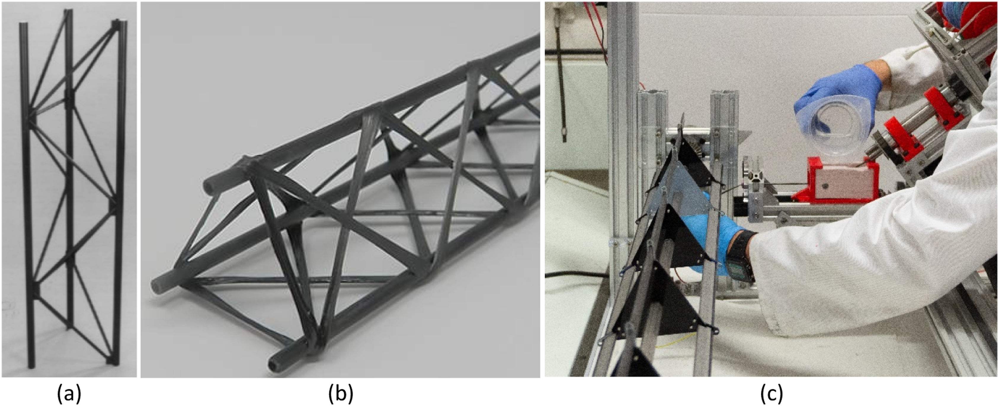
Similar to other filament winding-based approaches, the WrapToR manufacturing method is highly versatile for low-volume production as the geometry, materials, resin content, and processing parameters can be changed easily from run to run.9,10 However, due to its batch production nature, it is unable to achieve a continuous state of production as a means of lowering unit costs. 11 For large productions and highly slender parts, continuous processes such as extrusion for metals and pultrusion or pull-winding for FRP materials, although less flexible in terms of design versatility, provide lower price-per-part thanks to their high automation level and high production rate. 12 Combining the two aspects of the increased production rate with the mechanical performance of FRP truss beam-like structures would promote their adoption to a broader range of applications. To this end, the present paper showcases a novel approach to creating continuous high-throughput production of WrapToR truss beams by continuously winding the web members.
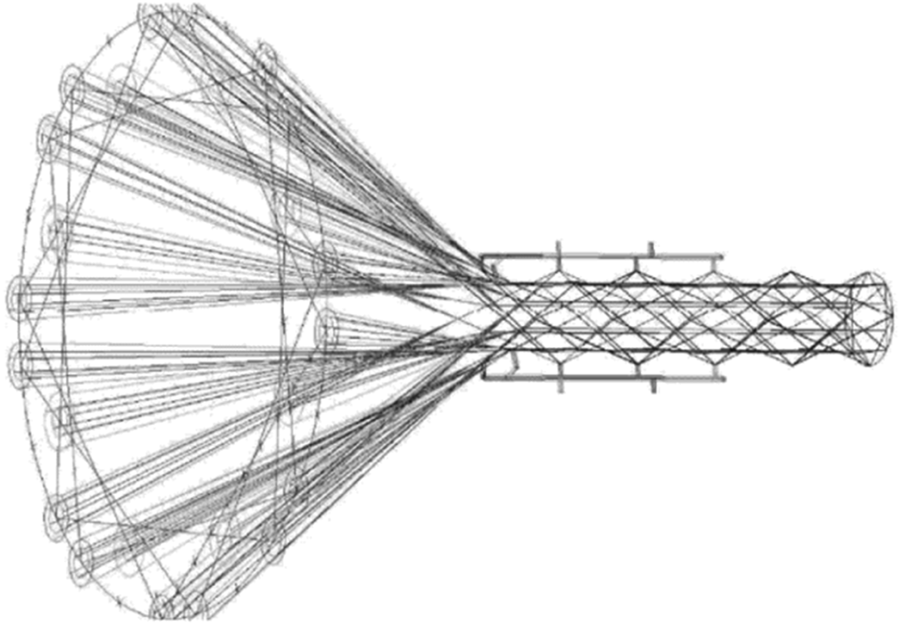
In the literature, there have only been a few related attempts to move away from batch manufacturing and develop high-throughput continuous production techniques for FRP beam-like truss structures. In 2006 Jensen et al. patented a novel braiding machine concept for manufacturing IsoTruss beams,13–15 with research into the idea being published from 200016–21 (Figure 2). The pyramidal outer geometry of the IsoTruss concept inherently makes for a captive mandrel unless some complex form of collapsible mandrel is used.
22
To avoid the manufacturing complexity this would create, the machine concept shown in Figure 2 adopts a mandrel-less design, and in its place uses a series of moving hooks to support the winding nodes – translating the hooks with the truss beam as it is wound.
13
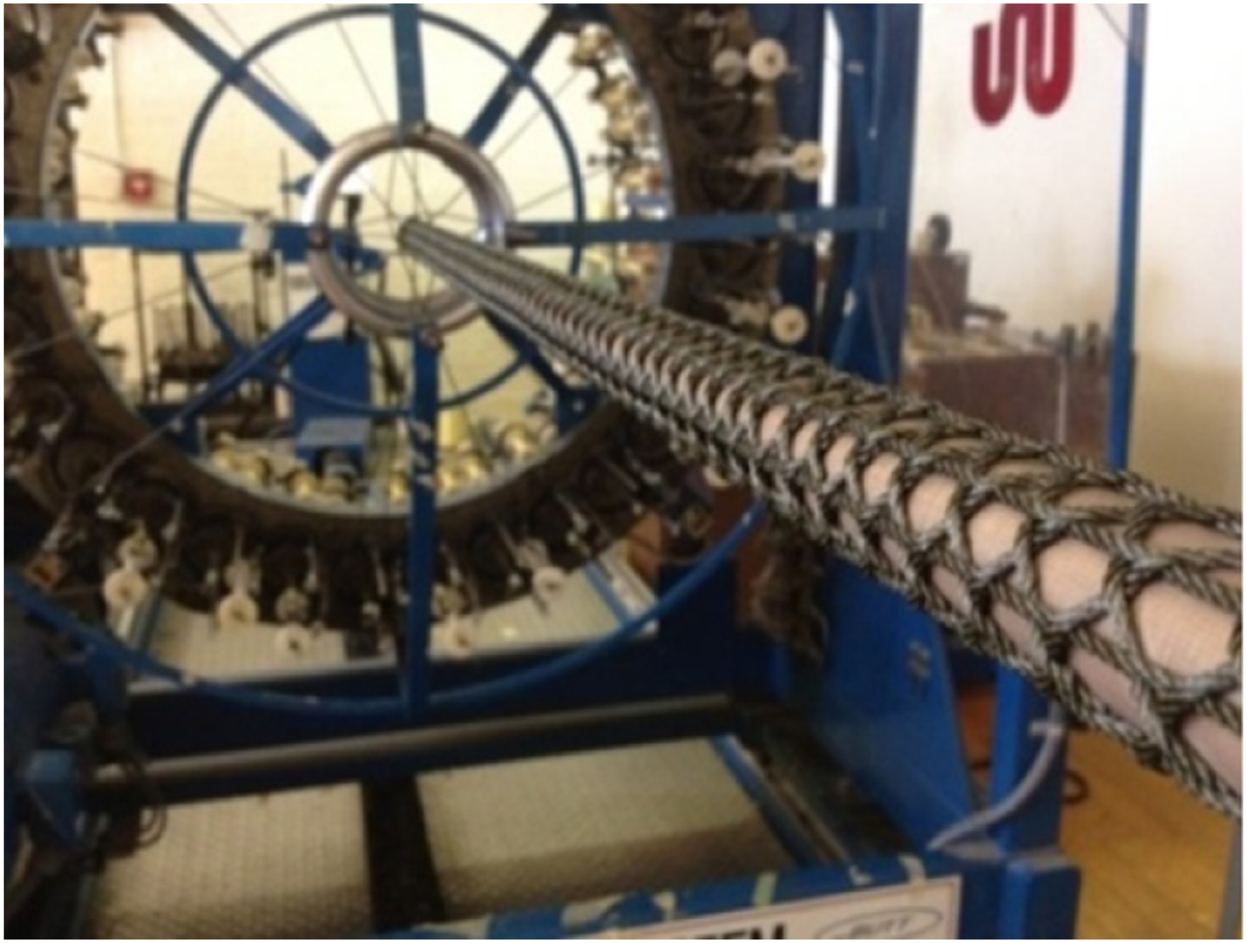
Although a remarkable concept, a functioning prototype of this braiding machinery has not been published. Researchers at Auburn University have used cylindrical mandrels and a braiding machine to produce truss beams with a technique called Near Net Braiding.23,24 This truss concept, referred to as Open-Architecture Composite Structures (O-ACS), has a circular cross-section whose properties can be tailored by changing the braiding patterns (Figure 3).12,25 The patented braiding equipment for high-throughput production of IsoTruss.
9
Carbon-Kevlar reinforced Open-architecture composite structure (O-ACS) produced by maypole braiding.
24
More recently, two companies have presented radically different approaches to manufacturing. In 2014, Tethers Unlimited26–28 presented the Trussellator prototype. As shown in the schematic representation in Figure 4(a), the Trussellator produces ‘first order truss beams’, while a second SpiderFab robot assembles these to form a ‘2nd Order Truss-of-Trusses’. The Trussellator and Spiderfab systems are envisioned to enable in-orbit manufacturing of large hierarchical space frames. In 2016, San Diego Composites presented the Advanced Composite Truss Printing System (ACT-PS) for in-orbit truss printing.
29
Thanks to its ability to print trusses much longer than itself while remaining compact, the ACT-PS was conceived to directly deploy a rolled solar panel array while simultaneously printing out the supporting truss beam. In 2018 the MIT Media lab group published Fiberbot, a compact robot that works in swarms and can crawl the tubular structure it prints
30
(Figure 4(b)). Lastly, in 2022, Li et al.
31
investigated the prototype of a ‘continuously buildable one-dimensional truss’ for the in-space fabrication of mega-structures.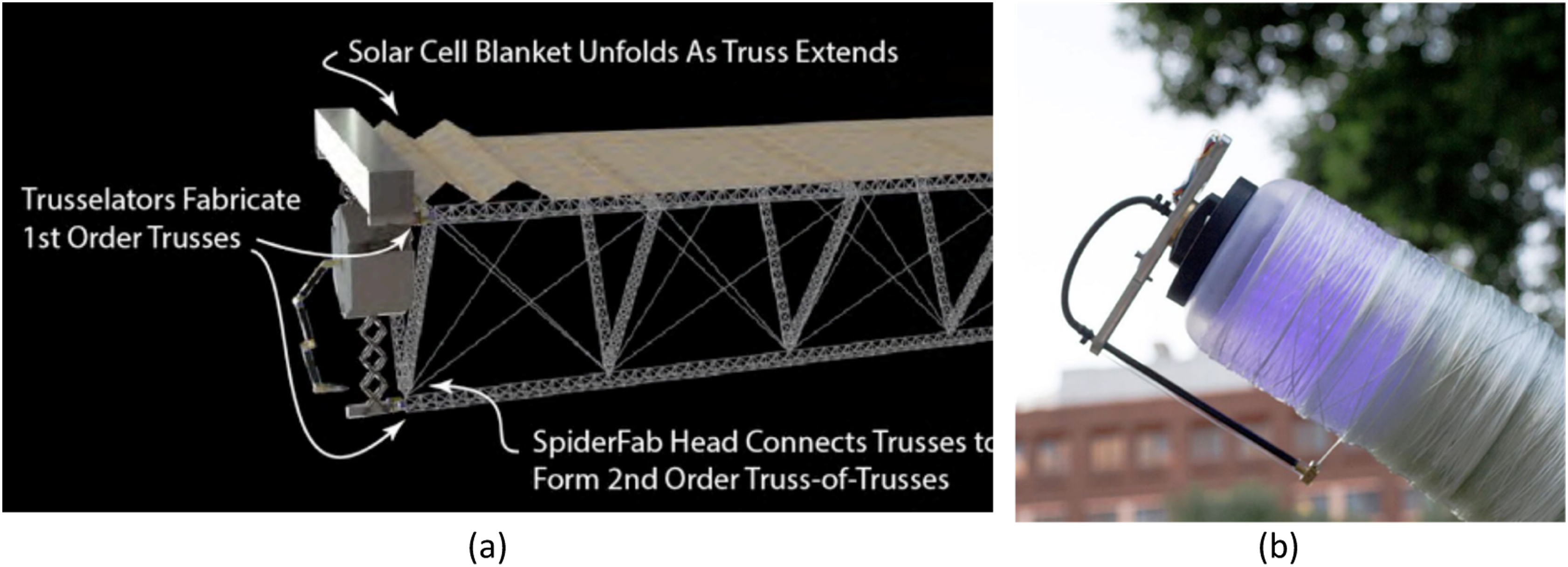
In this context of machineries for continuous truss printing, this work introduces a new concept for the continuous production of WrapToR truss beams: the first manufacturing process that will allow for single pass, winding of WrapToR truss shear webs onto the chord members. Since the entire process resembles the classical extrusion of beams, with raw materials constantly input from one side and the truss beam coming out from the other, we call this process WrapToR Trusstrusion.
This paper first introduces the overall concept before delving into the design and operation of a first working prototype. Trusstruded WrapToR beams are then presented along with a bespoke finite element analysis (FEA) code to predict their performances. Cantilevered tip load experiments validating the analysis and demonstrating the viability of the manufacturing technique are later presented and discussed before conclusions are drawn and future research directions outlined. As the primary objective is to prove the viability of this manufacturing concept and ensure production quality consistency, it’s important to state that a detailed analysis of the failure mechanism concept is currently out of the scope of this paper. This focus allows us to concentrate on the fundamental aspects of the WrapToR Trusstrusion process, setting a foundation for future research to build upon.
The WrapToR tTrusstrusion concept
To date, WrapToR trusses have been manufactured using a modified form of filament winding, with additional degrees of freedom to twist the winding yarn (Figure 1c). Pre-cured longitudinal UD pultrusions are held in place on a rigid internal mandrel while the winding head moves back and forth over the entire truss length to wind the FRP tows of the shear web members.
10
For a three-sided triangular cross-section truss with two directions of shear web winding, a total of six passes are required to complete the structure on conventional winding setups. Current WrapToR filament winding machines also induce a modest twist into the tows to give the shear members a circular cross-section that is more resistant to buckling.
10
Furthermore, winding tension is controlled to provide good consolidation pressure at the co-bonded nodes without needing vacuum bagging. The truss is left to cure on the mandrel, which is then disassembled to facilitate the removal of the part. However, since WrapToR trusses have the shear web lattice wrapped on top of the corners, with no interweaving with the longitudinal chord members, the same basic structure could instead be formed in a series of sequential, in-line processes: chord member feeding, shear web lattice wrapping, consolidation and cutting to length. Therefore, to obtain what is described here as Trusstrusion, the longitudinal members of the WrapToR trusses are inserted from a side and slide through the entire machinery while being wrapped from the outside. As will be further discussed in Section 2, the concept comprises two central modular systems taking care of these two main actions of feeding and wrapping the longitudinal pultrusions. The initial concept described herein uses pre-consolidated pultruded tubes for the chord members, which are sequentially inserted and joined to provide a quasi-continuous operation. In order to create a more truly continuous process, it may be possible in future iterations to pultrude the chord members in situ upstream of the winding module. To form the shear web members of WrapToR beams, part of the machine spins two sets of n different winding heads in contra-rotating directions, where n is equal to the number of sides in the truss cross-section (equivalent to the number of longitudinal members). This approach increases the required machinery complexity relative to the current filament winding approach (which uses a single winding head), but in turn, it avoids the need to rotate the mandrel. Most importantly, this manufacturing approach avoids the reciprocating motion present in traditional filament winding, and the necessity of disassembling the mandrel to remove the part. Without the need to reciprocate back and forth over the mandrel’s length in multiple passages, the Trusstrusion prototype can produce truss beams longer than itself, as shown in Figure 5. In this picture, together with a finished truss (4), it is possible to see the entire Trusstrusion setup composed of the main machine (1), the spool winding machine which impregnates and twists the shear-web member tows (2), and the power supply. The working principles of these two components will now be discussed in detail. The WrapToR Trusstrusion hardware, showing (1) the main prototype machinery, (2) the spooling station, (3) the power supply, and (4) a finished WrapToR Trusstrusion.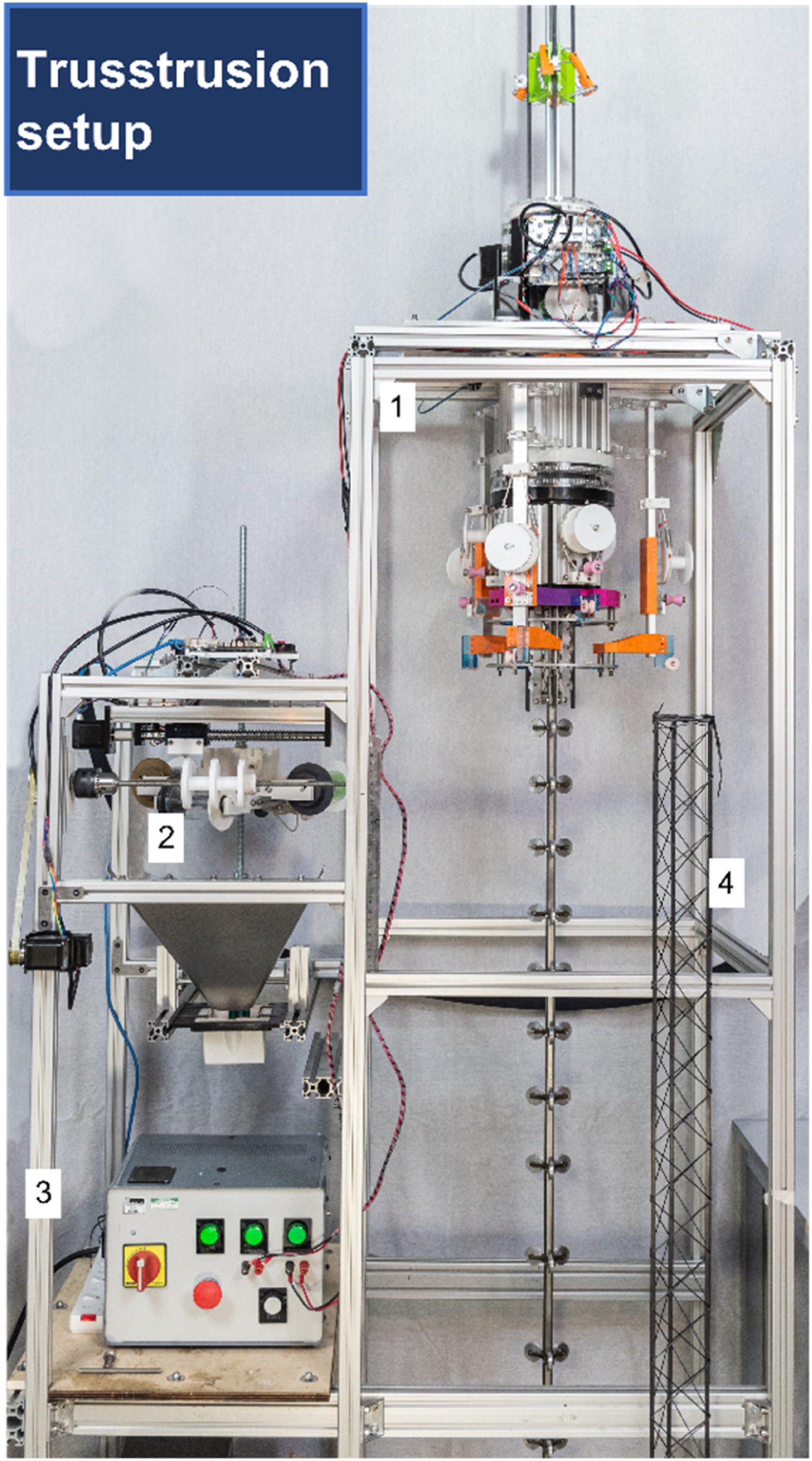
WrapToR Trusstrusion hardware prototype design
In converting the filament winding process into a continuous one, the Trusstrusion prototype uses a number of different modules arranged in series that perform the tasks required to fully wind a WrapToR truss. Figure 6 shows schematically how the machine comprises two main central systems, which are themselves composed of several modules. The first system deals with the feeding and driving of the chord member pultrusions, where an initial module holds the corner rods and a second one drives them. This last module houses geared stepper motors equipped with polymer drive pulleys and a control board, which drive the pultrusions into the second system, which performs the winding operation. Here, two contra-rotating frames wind a series of tows around the longitudinal members to form all the web lattice at once (two in each direction per chord member). Within the winding section, the longitudinal members are supported internally by an inner mandrel that enables them to be firmly held and accurately located while being driven through. After leaving the winding section, the truss continues to be supported by a series of discrete supporting pulleys that maintain the chord members’ spacing with reduced friction. The core components of the Trusstrusion main hardware, shown schematically and with photos of the completed machine, highlighting the feeding and winding systems arranged in series. Trusstrusion takes place from top to bottom, with the chord members being fed from above and finished trusses exiting below.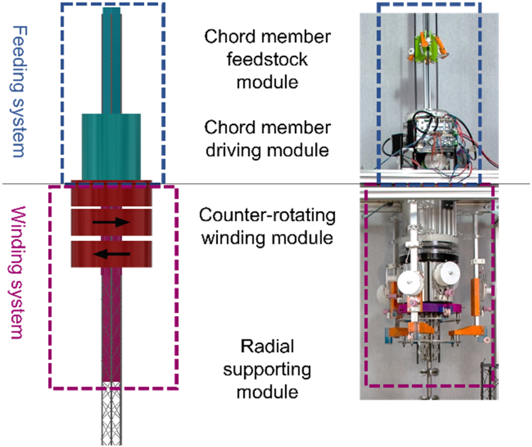
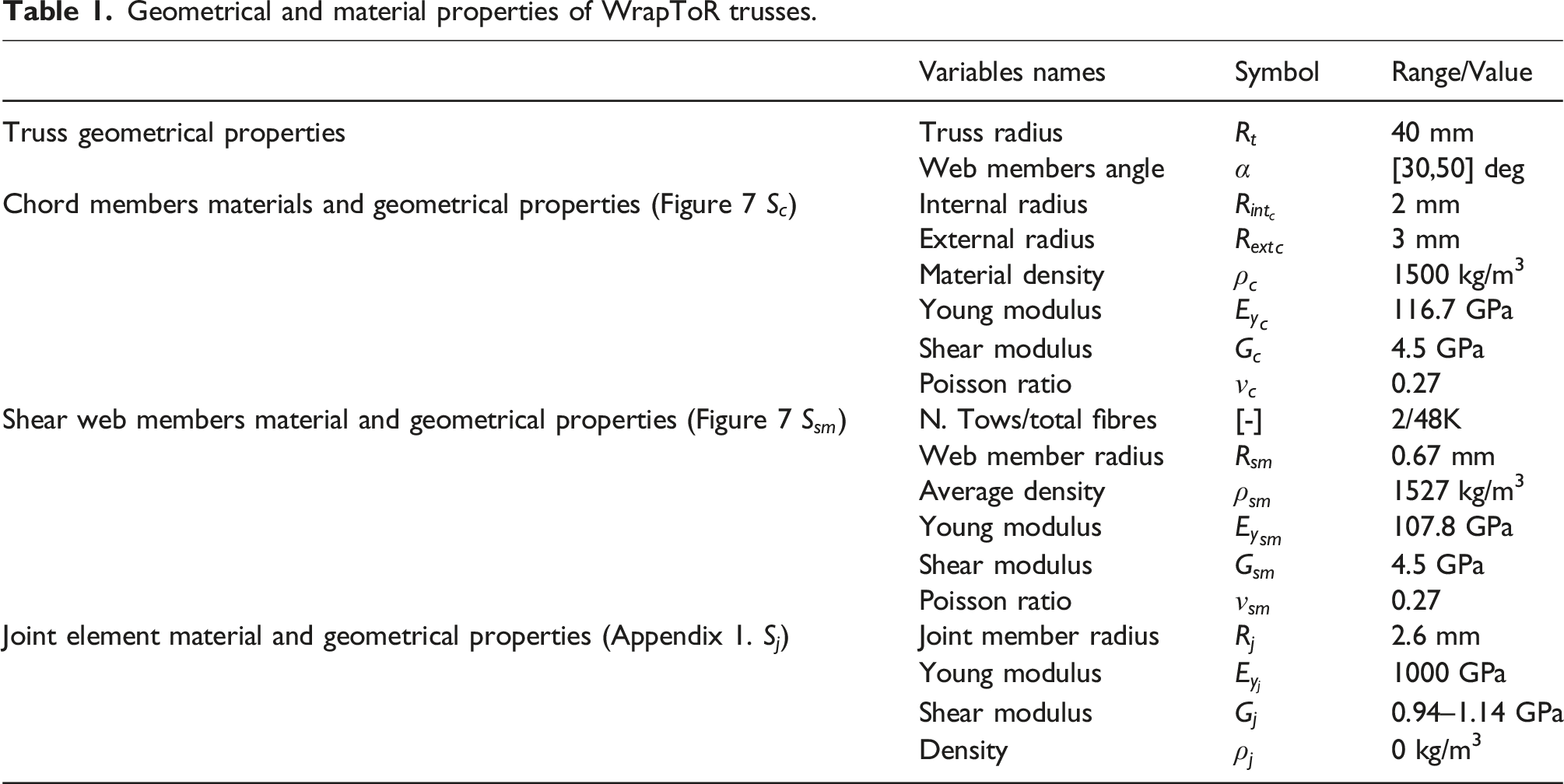
This series of modules can be adapted to wind trusses of a wide range of cross-section shapes and sizes. However, for this initial prototype machine, the focus is on triangularly shaped trusses with one fixed set of dimensions. The truss unit cell produced by this initial prototype has the shape shown in Figure 7, where the longitudinal members are unidirectional tubular pultrusions with an outer diameter of 6 mm. The geometrical and material properties of the trusses produced can be found in Table 1. The different modules of the machine design will now be discussed in more detail. Schematic representation of the Truss Unit Cell (TUC) of the WrapToR trusses produced by the current Trusstrusion setup. Geometrical and material properties of WrapToR trusses.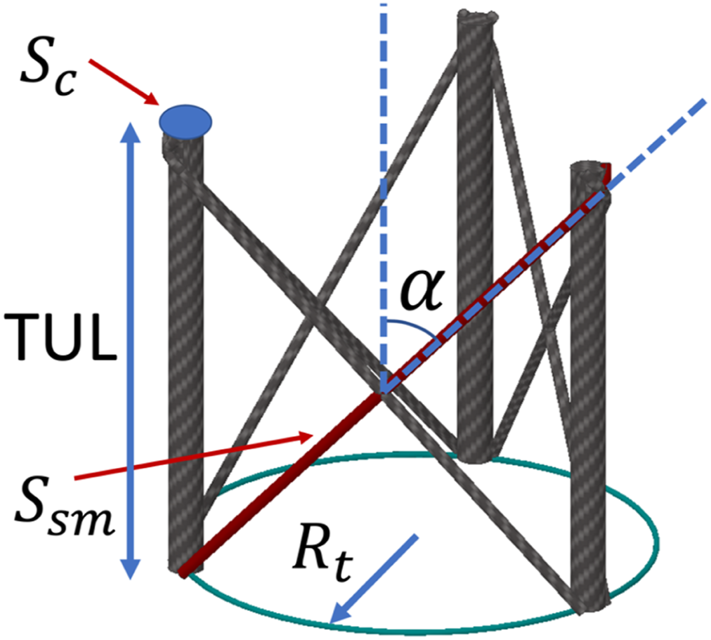
Feeding system
The Trusstrusion feeding system (Figure 8) is designed to drive each longitudinal chord member independently into the winding system. To do so, the driving module adopts three independent stepper motors connected to each tube using a series of gears and specially shaped drive pulleys. Each driving unit is then calibrated independently with the aid of optical switches to detect the presence of the tubes. The control of the motor is carried out with a commercially available 3D printer board. As shown in Figure 8, the current version of the prototype utilises a Duet 2 Wi-Fi board that is controlled with G-coding. Trusstrusion feeding module views showing the Duet 2 WiFi board (1), the paired geared motors for the winding module (2 and 3), the optical switch sensor board for detecting the chord members (4), the chords members being fed (5) and the three independently controlled motors (6, 7 and 8), feeding a single chord member each.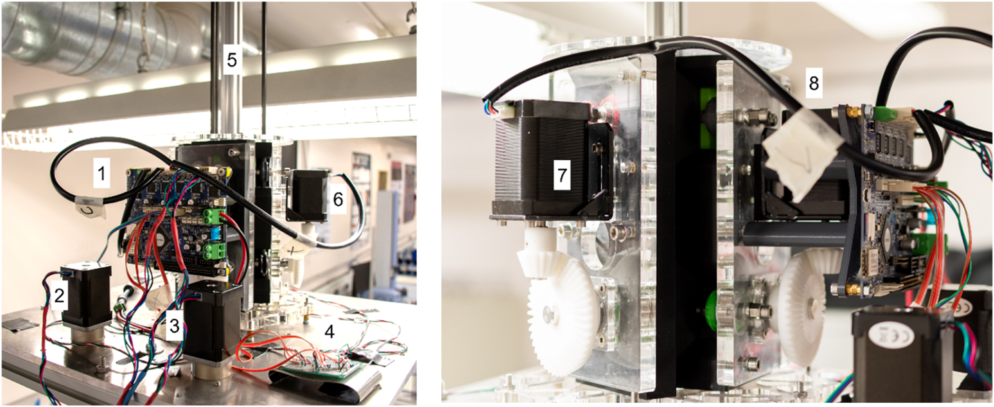
Since the central focus of this new design is to avoid the need for multiple winding passes, the feeding motion of the tubes replaces the classical alternate reciprocation motion of filament winding machine heads. In doing so, the total force required by the tube to slide through the entire machine becomes the sum of the longitudinal projection of the winding tension (approximately 20 to 30N) of all the tows, plus the friction from the support mandrel and ancillary machine parts.
The design of the machine and the use of tubular UD pultrusion for the corners allows for quick insertion of additional pultruded tube sections to maintain continuous reloading of the chord members. In this particular case, the 4 mm inner radius of the chord members allows for bonding in smaller pultruded rods which bridge the joint between successive chord members.
Winding system
The winding system is placed below the feeding system and winds the network of shear web members around the chord members. Since this first Trusstrusion prototype produces trusses with a triangular cross-section, the winding system must process six web tows simultaneously, winding three in both directions to fully populate the shear web of each unit cell. As shown in Figure 9, the winding module comprises two rotating frames holding three spools each, with all the pre-wet and pre-twisted tow needed for the entire truss. To obtain the helicoidal winding patterns in the two winding directions with the members equally spaced and appropriately oriented, the two rotating frames must rotate in opposite directions with the same angular velocity. The Trusstrusion winding module (a) composed of the two rotating drums (1 going rightward and 2 going leftward), the radial supporting mandrel module (3), the PTFE bobbins for the impregnated shear web member tows and the optical sensor to align the drums with the mandrel (5). The winding region is shown during operation in (b), where the six eyelets (6) are held by the two rotating eyelet holder rings which are separated by a distance equal to the Truss Unit Length (TUL).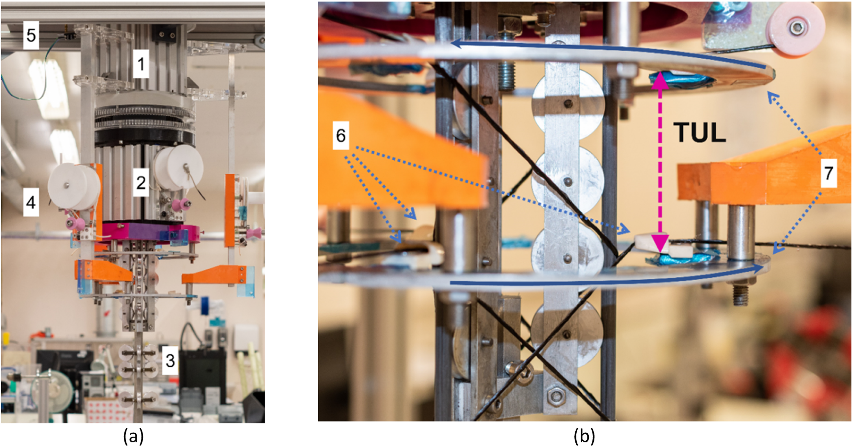
Contra-rotation is achieved thanks to two coaxial drums stacked around an inner body fixed to the frame and connected to the consolidation stage. The upper drum is directly driven via stepper motors; the lower drum is directly mounted over the same inner body, but is not actively driven. Instead, an internal ring gear on the upper drum drives another internal ring gear on the lower drum through a series of spur gears which reverses the direction of rotation while automatically ensuring equivalent rotational magnitudes and velocities between the drums. This also helpfully reduces the number of machine degrees of freedom which must be controlled. As a direct consequence of this design choice, the angular spacing of each web member is regulated by the machine geometry rather than by its control system. In Figure 9, it is possible to visualise how the winding eyelets on each of the support rings are equally spaced at 120° intervals. Furthermore, as shown in Figure 9, the two frames holding the three eyelets are placed at a distance equal to the truss unit length (TUL) to ensure that the nodal junctions of the secondly wound series of web members coincide with those of the first. It is possible to adjust this distance manually in the current design, and future designs could automate this degree of freedom through incorporation of a linear drive. Varying the TUL while keeping the tube distance constant corresponds to a variation of the web member orientation angle,
In Figure 9, the upper portion of the consolidation module can be seen. This is composed of three parts, the first of which is attached to the fixed frame at the top of the machine and then runs through the rotating drums, a second (the one visible in Figure 9) in the winding region and a third which extends past the winding region to support the truss as it cures. Here, it is possible to see how the tubes are supported from inside, from the winding region downward, with a series of pulleys that guide and locate the three tubes to ensure their correct positioning is maintained under the forces created during winding. As it will be further discussed in section 2.3, this last part of the consolidation module can be removed to simplify de-moulding.
Machine installation and operation
This initial Trusstrusion hardware prototype is installed in the Bristol Composites Institute (BCI) laboratories, as shown in Figure 5. The central machine body is mounted in a vertical configuration with the feeding unit and the winding one divided by an aluminium plate which is rigidly connected to the machine frame. The aluminium plate is placed at 2.2 m from the ground and the clearance from the ceiling is 1.7 m. Since the winding module is approximately 0.5 m tall, and the consolidation stage 1.5 m tall, the bottom of the entire winding system is almost at the floor level. Alternatively, a horizontal configuration could also be used. A horizontal orientation would decouple the length of truss produced from the vertical height of the space in which it is installed (allowing longer lengths), the vertical configuration chosen for this first prototype has the advantage of minimising flexural bending of the machine modules under gravity, while also saving floor space. Furthermore, a vertical arrangement could potentially be installed across multiple stories with in-line systems to speed up resin curing and increase processing speeds. That all being said, the Trusstrusion prototype in its current mounting position can manufacture trusses of up to 1.5 m in length. Once the curing cycle has reached the setting point sufficient for de-moulding, the chord members are cut at the ends of the wound shear members (leaving portions of the chord member tubes in the feeding line), allowing the complete removal of the entire last part of the consolidation module. As can be seen in Figure 10, once this module is removed, the presence of the pulleys allows it to slide off the consolidation module smoothly. This module can then be re-installed, and a second run can start. Detail of a truss during consolidation over the mandrel pulleys, with the TUL highlighted.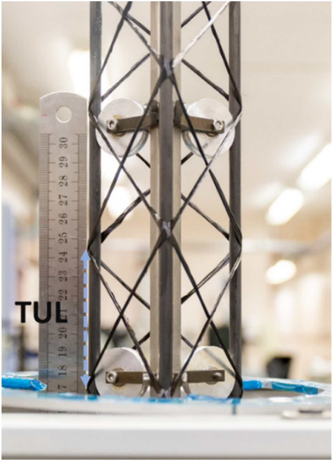
Materials processed
As previously explained, the current Trusstrusion hardware requires pre-wetted and pre-twisted carbon tows. Therefore, there is the need to correctly control both these parameters for the six separate shear web windings. To do so, these operations are performed on a custom design winding machine that is part of the Trusstrusion setup shown in Figure 11. This wetting-spooling station is composed of several parts: a spinning creel (1), a resin bath with a resin recovery funnel (2-3) and a spooling area (4), with a spinning mandrel and a carriage mounted on a linear stage, similar to conventional filament winding machinery. Similar to the WrapToR winding machine presented in Hunt et al.,
10
the dry spools are held on a rotating creel which keeps the various tows separated and in tension until they reach a stainless-steel impregnation pin at the bottom of the bath. The now wetted and twisted tow then passes through a ceramic eyelet placed on the carriage, where it is wound onto the PTFE spools used by the Trusstrusion winding module. The amount of twist is adjustable by proportionally controlling the rotation speed of the winding mandrel relative to the rotation of the creel. To facilitate the loading stage operation, the pre-wetted and pre-twisted tow is initially wound on 3 PTFE spools at once, as shown in Figure 11. Once finished, the operator loads the first three on the machine while the second set gets spooled. Trusstrusion hardware spooling system: (1) spinning creel, (2) resin bath, (3) resin recover funnel, (4) spooling area, (5) Duet control board.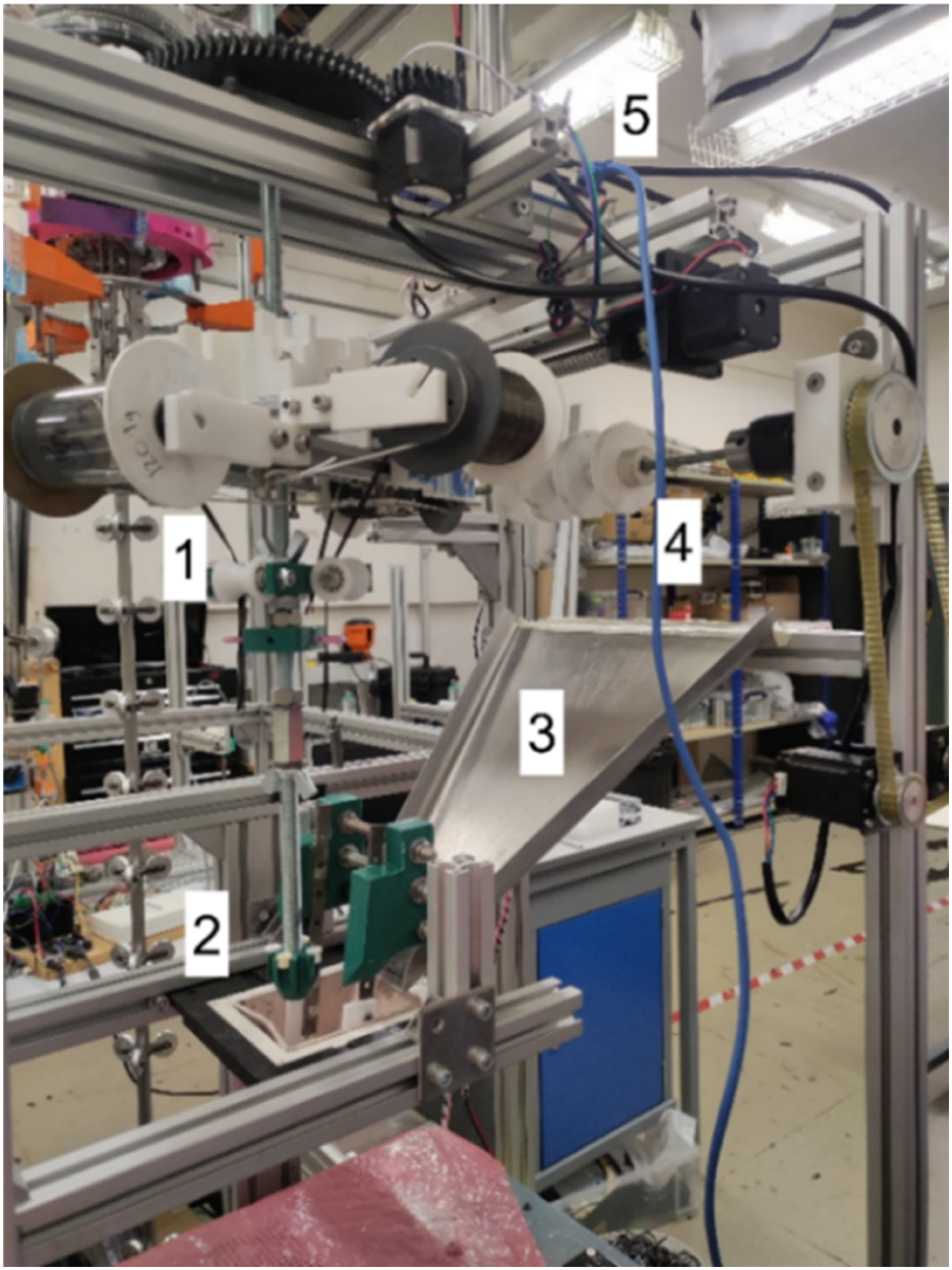
Although it is possible to use any continuous fibres and many resin types, only carbon fibres and epoxy resins have been used for the web members of the truss beam samples presented herein. Since ease-of-use and versatility were considered key factors at this stage of development, off-the-shelf materials such as user-friendly resins with a long pot life, a long curing time (24h), and a medium-low viscosity to facilitate impregnation were used. In particular, the resin is the EL2 with AT30 slow epoxy hardener, while the fibres are intermediate modulus fibres from Tenax (TENAX IMS65), with 24k fibres per tow. Previous studies 10 investigated the mechanical properties of shear members made from two slightly twisted tows of Tenax IMS65, which were found to have an average Young Modulus of 107.8 GPa.
The chord members are commercially available UD tubular pultrusions with an outer diameter of 6 mm and inner diameter of 4 mm, supplied by EasyComposites®. The current setup is equipped with sets of pulleys custom made to work with longitudinal members of 6 mm outer diameter. The tensile properties of these tubes were experimentally measured, as discussed in Section 4.1 and the properties are summarised in Table 1.
Truss modelling
Previous studies have shown that WrapToR truss beams can be accurately modelled numerically through finite element analysis using three-dimensional beam elements with six degrees of freedom per node.
32
Capturing the truss geometry accurately is important. Since WrapToR trusses are made via continuous fibre winding, they have helicoidal web members laid around the longitudinal chord members. Such overlap induces a certain eccentricity of the web members’ ends with respect to the chord members. Therefore, to account for the eccentric junction of continuous fibre composite members, we adopt an additional beam member called ‘joint element’ (Figure 12), which was first introduced by Hunt et al.
10
Therefore, the geometrical discretisation into a finite element model is performed using three sets of cross-sectional properties: one for the tubular chord members, one for the shear web members, and a third for the joint element. To help visualise the materials used in each mesh segment, Figure 12(a) adopts a colour scheme as follows: black for the chord members, blue for the shear members and magenta for the joint elements. Geometrical and mechanical properties of all the truss constituents are reported in Table 1 and the tensile properties of the UD chords are analysed in Section 4.1. As for the shear members, since the material used is the same as,
10
we adopt the same experimental values, which are reported in Table 1, which also gives the average equivalent radius of the shear members ( WrapToR truss beam modelling, (a) Mesh layout used for truss analysis and (b) detail of the side view of the mesh geometrical layout overlaid onto an actual WrapToR truss highlighting the joint element segment (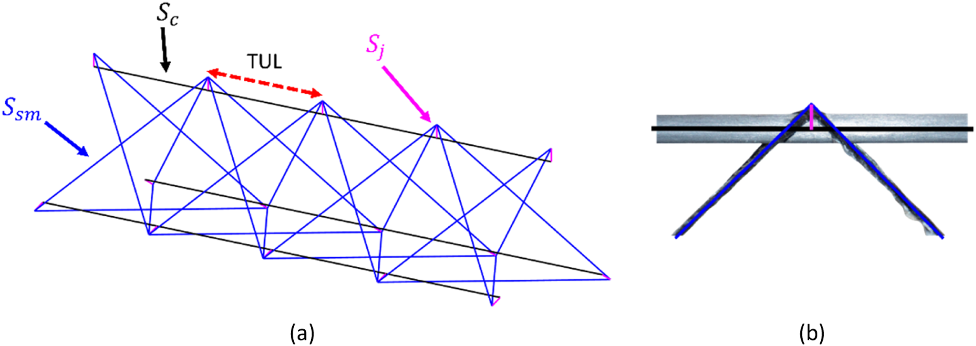
The joint element properties are obtained by considering both the resin used for the shear members and the geometry of the truss junction itself. With reference to Hunt et al.,
33
the joint element is conceived as a massless beam element forced to deform only in shear through the use of a realistic shear modulus (0.94–1.14 GPa) but arbitrarily high Young’s modulus. The cross-section of this joint element is modelled as a round rod whose radius
Having established the geometrical and mechanical properties of the truss, a finite element (FE) model is then built up in a bespoke, parametrically defined mesher, written in MATLAB®, that uses Timoshenko beam elements with a third-order polynomial discretisation.
32
The FE problem is, therefore, of the form described in equation (1).
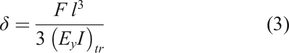
Although the stress field is not central in this study, it is obtained by post-processing the forces acting at the two nodes of each element and then using the compatibility equations of the Timoshenko beam. Since beam elements are used, they can also transmit moments and shear loads. Therefore, each element experiences a non-uniform stress field over its cross-section, which is sampled in several locations along the cross-section.
Experiments
To assess the mechanical performance and consistency of WrapToR truss beams made with the first Trusstrusion hardware, four specimens were tested under transversal flexural loading in a cantilever configuration. These tests were performed on a custom testing rig using a stepper motor driven loading probe, with a load cell mounted in series and a displacement transducer mounted in parallel to allow for simultaneous recording of load and displacement through a LabVIEW® data acquisition system. In addition, the tubular pultrusions used for the chord members were also independently characterised via tensile testing in order to provide accurate material properties for the analysis work. The pultrusion testing will first be discussed, followed by detailed discussion of the flexural testing and associated validation of the analysis approach.
Chord member tubular pultrusion tensile tests
Since no specific ASTM standard testing technique exists for UD tubular carbon pultrusions, coupons were made (Figure 13(b)) and tested with an Instron® testing machine (Instron 1342) equipped with a 250 kN loadcell. Strains were captured with an Imetrum® video gauge system recording at 10 Hz (Figure 13(a)). The pultruded tube tensile specimens have a 130 mm central gauge length with 80 mm long bonded tabs on each end. The end tabs are made from tubular steel, with a 6.2 mm internal diameter and 12 mm external diameter, with the pultrusions inserted to the full depth of the end tab tube (the overall length of the pultrusions was therefore 290 mm). An inner steel rod was also inserted to further prevent crushing of the pultrusions under clamping pressure, and everything was bonded with Araldite® 2014-2 epoxy (Figure 13(b)). The loading rate was set to 2 mm/min, and the stiffness was then computed through a linear regression in the strain range of 0.02%–0.2%. Dividing the measured rigidity by the cross-sectional area of the samples gives a Young Modulus value of 116.7 GPa. A summary of the geometrical and physical properties of the pultruded tubes can be found in Table 1. (a) Stress-Strain filtered video gauge readings of UD tubular specimens used for the chord members of WrapToR trusses (OD 6 mm, id 4 mm). The specimens in (b) were tested with an Instron® testing machine with a 250 kN loadcell and strain measures (up to three per specimen) were collected with an Imetrum® video gauge system.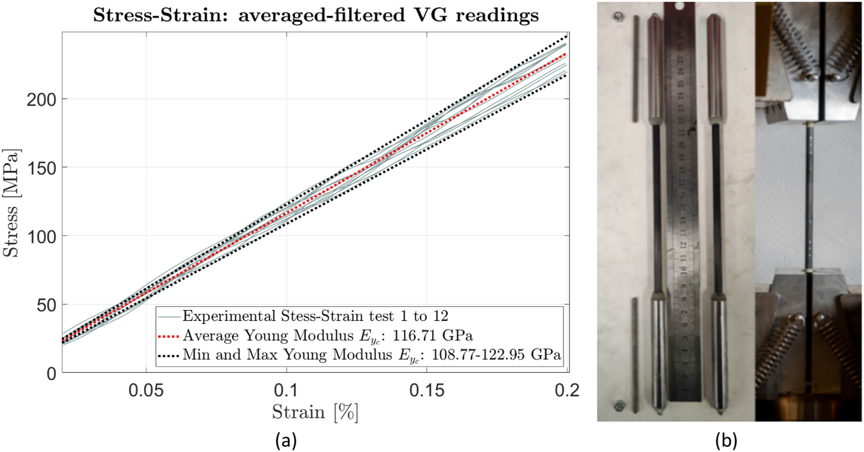
Truss specimen preparation
The truss specimens required some minor alterations to make them suitable for flexural testing. First, the trusses were trimmed to length, with a total of 19 unit cells in three of the trusses and 18 in the fourth. To allow for cantilevering, the three chord members on one end of each truss were fitted with threaded end connectors, which consisted of 50 mm lengths of M12 mild steel threaded rod with a 6.2 mm hole drilled through to fit the pultrusions with an additional gap of 0.1 mm for the epoxy adhesive. An example of a cantilever truss sample clamped onto the testing rig can be seen in the picture in Figure 14. The bolted connection clamping the truss to the testing rig.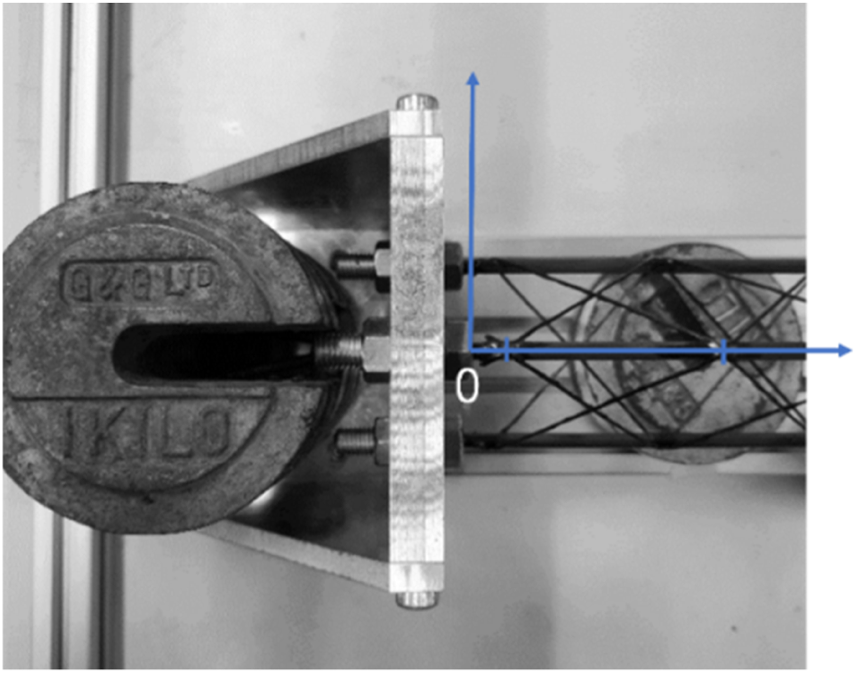
Truss specimens manufacturing variability
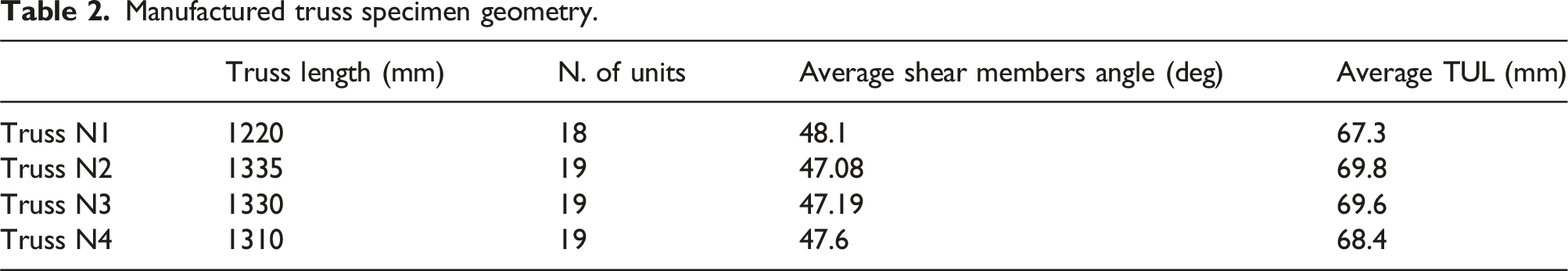
The truss specimens were designed to have a TUL of 70.5 mm, corresponding to a 47° shear member angle. However, during manufacture of the test specimens, a small variation in the TUL was noticed, which was determined to be the result of occasional slippage between the chord members and the drive pulleys which feed them into the winding unit. This has the effect of creating a reduction of the average TUL and thus a variation in the shear web member angle. To better understand this variation, the lengths of every unit cell on every truss were measured as shown in Figure 15. Here, we see all of the unit cell lengths, the averages for each specimen, and the target value of 70.5 mm (in magenta). It can be seen that Truss N2 has the least variation in TUL as well as having an average TUL closest to the desired value; while Truss N1 is the most affected by this variability, showing both the lowest TUL and the highest deviation of its average value. A direct consequence of this TUL variation is the fact that the truss samples all have a slightly different length. Therefore, with reference to the Datum shown in Figure 14, Table 2 displays the total length, average shear web angle, and average TUL for each specimen. Ranging from 47.3° to 48.3°, the shear web angles obtained are greater than the target value of 47°. From a modelling perspective, in this work, the total truss length variability was captured within the analysis by employing dedicated FEA models, with each model matching the average TUL of its corresponding specimen, but not the variation in TUL along its length. Practically speaking, the levels of accuracy and consistency achieved with this first prototype machine are less than desired, but still reasonably good. There are also a number of potential improvements to the drive system which would reduce slipping that will be explored in future work. TUL variability across the various units of the truss samples. Manufactured truss specimen geometry.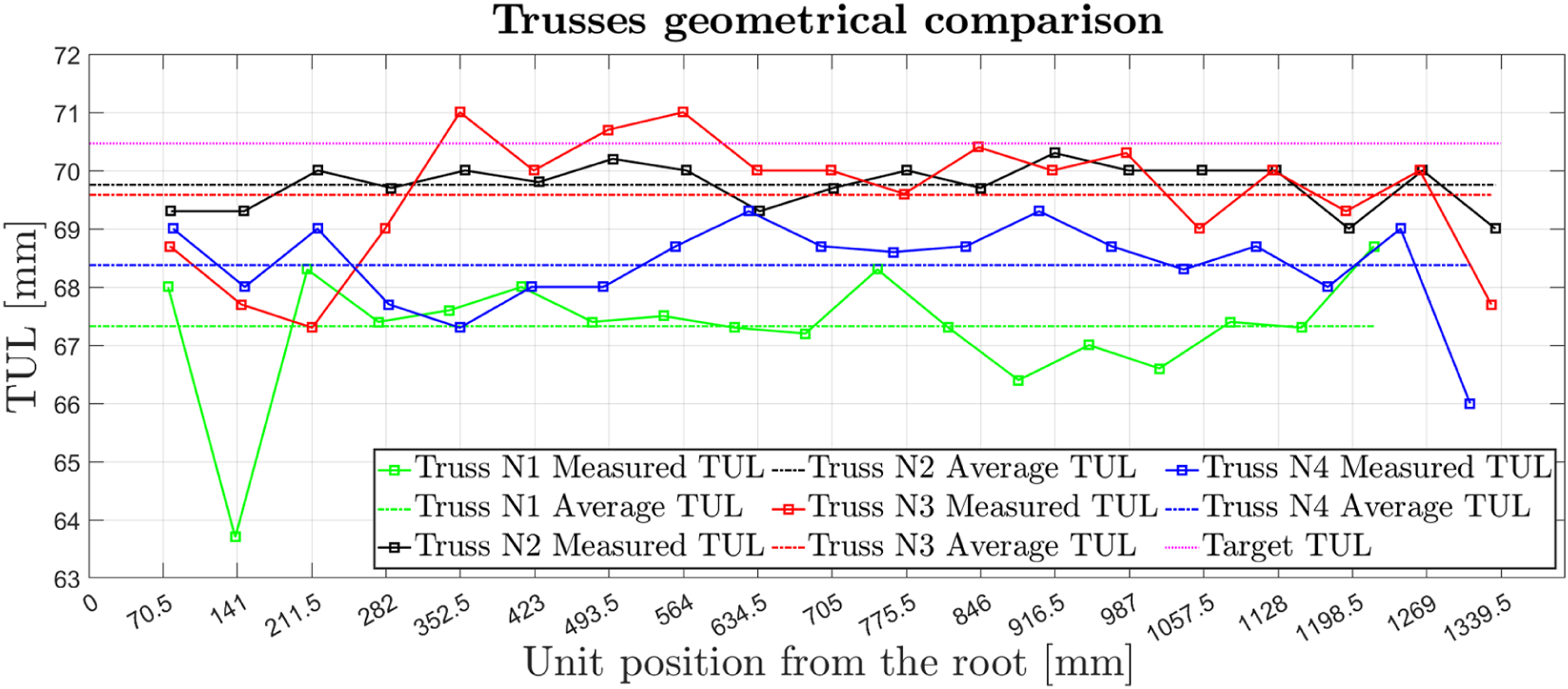
Cantilevered test rig and testing procedures
The length of the trusses made cantilevering them within traditional mechanical testing machines complicated, so a bespoke test rig was instead developed. Shown in Figure 16(a), it consisted of a rigid frame with a reinforced mounting bracket, and a moveable load application and measuring device, which included an electromechanical actuator, displacement sensor, and load cell; with control and data acquisition provided by a custom program running in LabVIEW® 2021. The truss mounting bracket was made of 15 mm thick aluminium plates with corner gussets bolted to a large base extrusion. Steel counterweights were also used to balance the applied bending moments and minimise deformations in the rig itself. The load application device consisted of a linear stage with recirculating ball bearing linear guides driven by a geared stepper motor acting through a lead screw with 0.5 mm pitch. Mounted to the moving stage was a 2 kN load cell (Omega® LCMFD-2 KN paired with the Omega® DP25B-S strain gauge panel meter), which was used to measure the applied loads. Between the moving stage and fixed frame, and in parallel to the load cell, a precision linear potentiometer (Gefran® Linear Transducer: PY-2-F-050-S01 M) was mounted to measure the applied displacements (Figure 16(b)). Experimental testing setup, (a) cantilever rig showing the linear stage, the electronic equipment, and the LabVIEW VI running. As shown the rig is equipped with several linear potentiometers spaced along the truss, though only the data from the one in the load application system at the truss tip was used in this study. (b) closeup of the free end of the testing rig, showing the load application device and its components: (1) the load cell, (2) the linear stage, (3) the linear potentiometer, (4) the geared stepper motor and (5) a dial indicator backup for displacement monitoring.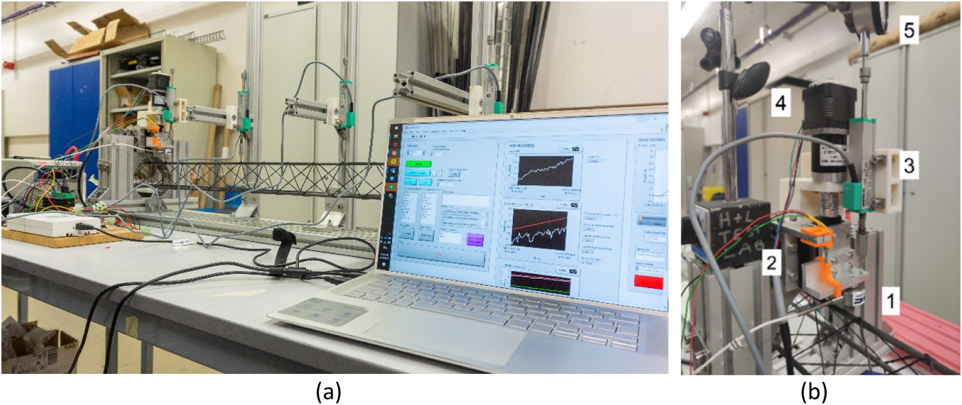
A transverse bending load was applied to the uppermost chord member of the truss directly onto the 15th nodal junction, counting away from the root. The reasons for this position are twofold: firstly, since the scope of this investigation is to obtain a global stiffness measure for the entire truss, applying load directly into a nodal junction provides displacement readings that are less affected by local deformations of the individual truss members. 33 Secondly, the load is applied somewhat inboard from the end of the truss to reduce the impact of free end effects (e.g. cross-section distortion). It is also worth noting that since the trusses have slightly different lengths, the distance of the load application point from the root changes slightly among the samples.
Furthermore, considering that due to production variability the three-fold symmetry of WrapToR trusses might be affected, the specimens were tested in three different orientations. To minimise measurement error, the readings were repeated at least 10 times along each truss orientation. The readings related to each orientation were then postprocessed in MATLAB®. The data was first filtered to remove any high frequency noise using a low pass Butterworth filter, with a cut-off frequency of 0.25 Hz. Linear stiffness values
Results & discussion
Validating the bespoke modelling tools developed here was a key objective of this study, alongside comparing them against experimental data. As such, it was imperative to benchmark our FEA outcomes against those from commercial software. To this end, we performed MATLAB® FEA analyses and compared these with Abaqus® simulations, importing geometries and properties via a ‘.inp’ file generated by the FEA script. Notably, the average discrepancy between our script and Abaqus®, when employing ‘B31’ beam elements – 3D linear beam elements that accommodate transverse deformations – was approximately 0.25%. This finding validates the accuracy of our custom-developed FEA code in comparison with standard tools. However, for brevity, and considering the negligible differences, we only present contour plots of the deformation along the Y-axis of Truss N2 under a 10 N load from both software packages in Figure 17. MATLAB-Abaqus comparison of Truss N2 deformation under a 10 N concentrated load on node number 94, which belongs to the nodal junction of unit number 15, and that in the undeformed configuration is found at 1055 mm from the root.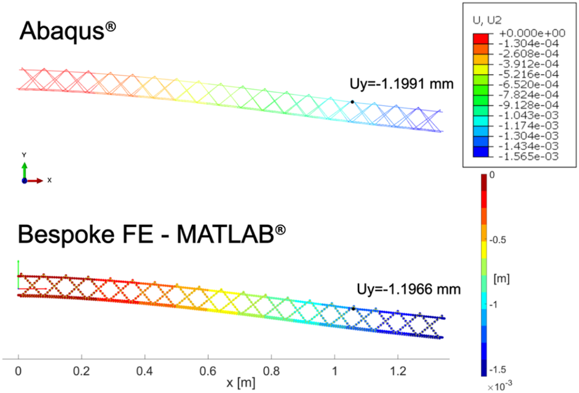
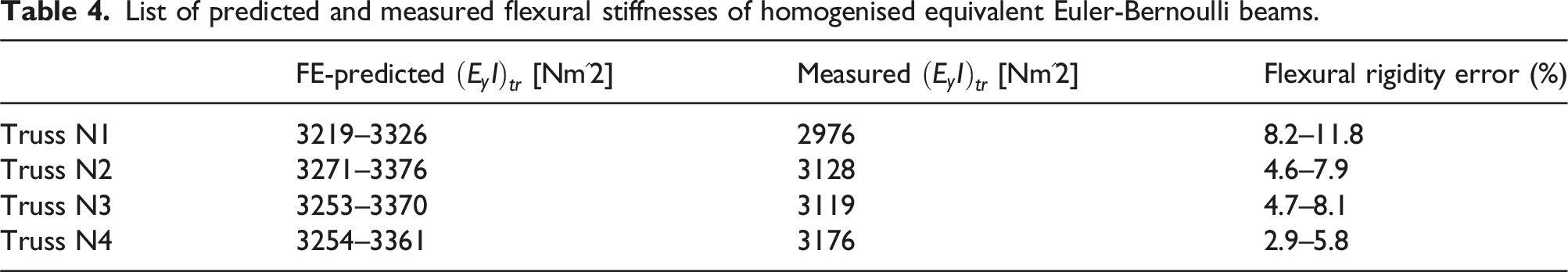
The experimental results for the four truss specimens are shown in Figure 18. The force versus displacement data is plotted for each of the three orientations for each truss, alongside a linear regression for the average of all three orientations. The FE results are also plotted, with ranges in colour reflecting the upper and lower bounds of the shear modulus for the resin in the joint elements (0.94 GPa and 1.14 GPa), which was not directly characterised, as discussed above. Experimental force versus displacement results for the four truss specimens. Dashed lines show results for the different truss orientations, and the solid lines show the linear regressions considering all three orientations. The FE predictions are shown as coloured in triangular segments, representing results with the upper and lower bounds of shear modulus for the joint elements.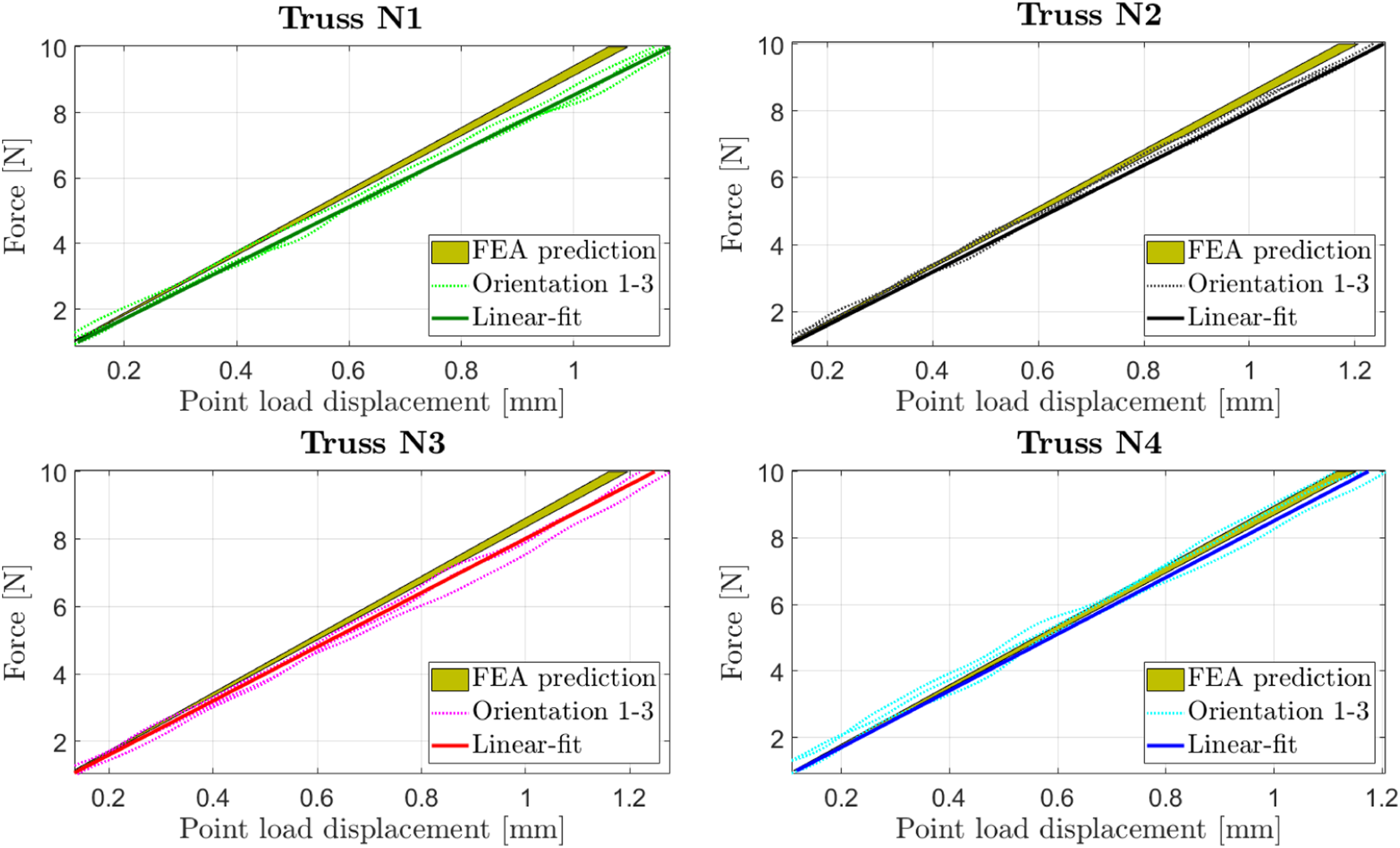
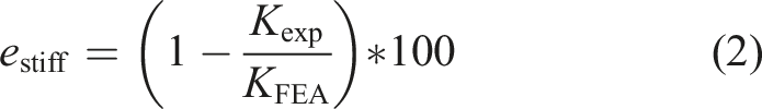
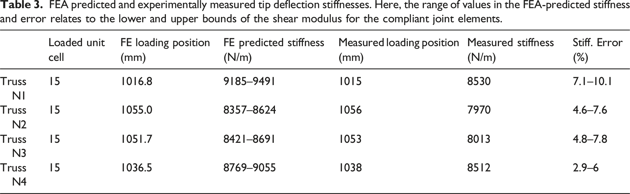
FEA predicted and experimentally measured tip deflection stiffnesses. Here, the range of values in the FEA-predicted stiffness and error relates to the lower and upper bounds of the shear modulus for the compliant joint elements.
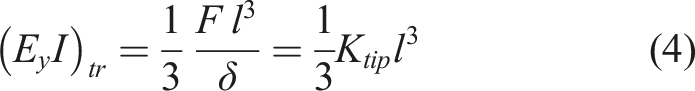
List of predicted and measured flexural stiffnesses of homogenised equivalent Euler-Bernoulli beams.
Conclusions
In conclusion, this paper introduced and demonstrated for the first time a manufacturing process that is capable of continuous production of Wrapped Tow Reinforced (WrapToR) truss beams through a process known as Trusstrusion. This process is envisioned as an alternative, parallel development stream to the existing filament winding approach to making WrapToR trusses that trades reduced dimensional flexibility for continuous production as a means of increasing throughput and reducing unit cost.
The design concept behind the machine was first presented, where the rotating mandrel and reciprocating single winding head of traditional WrapToR manufacturing is replaced with chord members being fed into a pair of contra-rotating winding drums which each support three separate winding heads arranged at 120° intervals. A non-rotating, non-translating mandrel supports the longitudinal members during wrapping, and is equipped with a series of pulleys to allow the truss beam to advance through the machine with minimal friction.
The design and implementation of a first Trusstrusion prototype were then presented, along with details of the manufactured truss specimens. Detailed measurements of the truss bay lengths identified larger than desired variations that are likely due to slipping in the drive pulleys of the feeding unit, which can be addressed in future design iterations. Finite element analysis and cantilevered tip loading experiments were then used to assess the bending stiffness of these truss specimens, showing remarkably high levels of stiffness, good consistency in the measured bending rigidity, and good agreement between FEA and experiment. It is important to highlight that this initial work primarily focuses on establishing the foundational viability and consistency of the Trusstrusion process, and that there is much work to be done on understanding and optimising the detailed aspects of both the manufacturing process and the resulting mechanical performance of these truss beam structures.
Overall, this work has demonstrated that this novel method of composite truss beam manufacturing can indeed be realised in practice, with promising initial results motivating further research. Going forward, the next steps will involve refining each machine module to increase production rate. This will include implementing impregnation on-board for the winding module and installing heating systems over and around the radial support module to reduce consolidation time.
Footnotes
Declaration of conflicting interests
The author(s) declared no potential conflicts of interest with respect to the research, authorship, and/or publication of this article.
Funding
The author(s) disclosed receipt of the following financial support for the research, authorship, and/or publication of this article: This work was supported by the Engineering and Physical Sciences Research Council through the EPSRC Centre for Doctoral Training in Advanced Composites for Innovation and Science [grant number EP/L016028/1].
Appendix 1 – Truss unit geometrical discretisation
Research conducted by Hunt et al. 10 and Gurley et al. 24 demonstrates that in composite lattice beams constructed with continuous fibre, the nodal junctions exhibit offsets between the neutral axes of adjacent members. Specifically, in WrapToR truss beams, the shear web members, which are wrapped around the chord members from the outside, overlap the tubular chords. This overlap causes the nodes to bulge outward relative to the axis of the beam. To accurately model the mechanical behaviour resulting from the offsets between shear web and chord members, Hunt et al. 10 introduced a conceptual joint element to bridge the two. Specifically, these joint elements, representing the adhesive interface between the chords and shear webs, are modelled as inextensible cylindrical rods capable only of shearing deformations. The dimensions of these joint elements, including their length and radius, are determined through two geometrically based methods.
The equivalent round area of the joint element is found by considering the schematic shown in Figure 19 and equations (5) to (8), which essentially ‘unwrap’ the portion of each shear web member which is bonded to the longitudinal member at each node, while accounting for the overlapped portion of the shear web. Schematic representation of the joint element member cross-sectional area comprising the bonding patches of the two shear web members.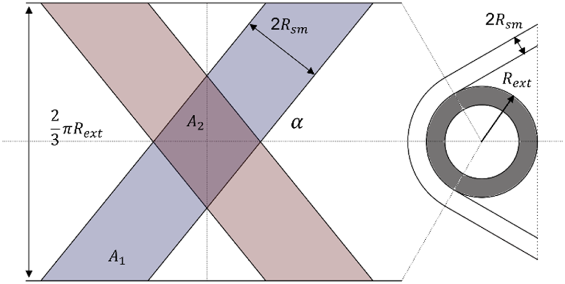
The length of the joint elements is determined from the geometrical layout of the finite element mesh. In particular, as shown in Figure 20, the repeating unit of a WrapToR truss mesh is defined between two sets of joint elements, with a longitudinal spacing equivalent to the Truss Unit Length (equation (9)). Figure 20 c shows a schematic of a WrapToR truss that has been ‘unfolded’ to better show the geometry definition of the shear web and its interaction with the chord members. From this we can see how the TUL is the sum of an Unsupported Unit Length (UUL) with the Joint Unit Length (JUL), as shown by equation (9). Schematic representation of the geometrical idealisation adopted to reduce the truss geometry (a, (b) to a series of 1D beams for the FEA mesh. Flattening the outer surface of a truss as shown by the sketch on the left (c), it is possible to obtain the longitudinal positioning of the joint element beams, which corresponds to the TUL. The schematic representation on the right (d) shows the radial position of the ending node of the joint element lines, which is fixed at the projected crossing point of the axes of the web members.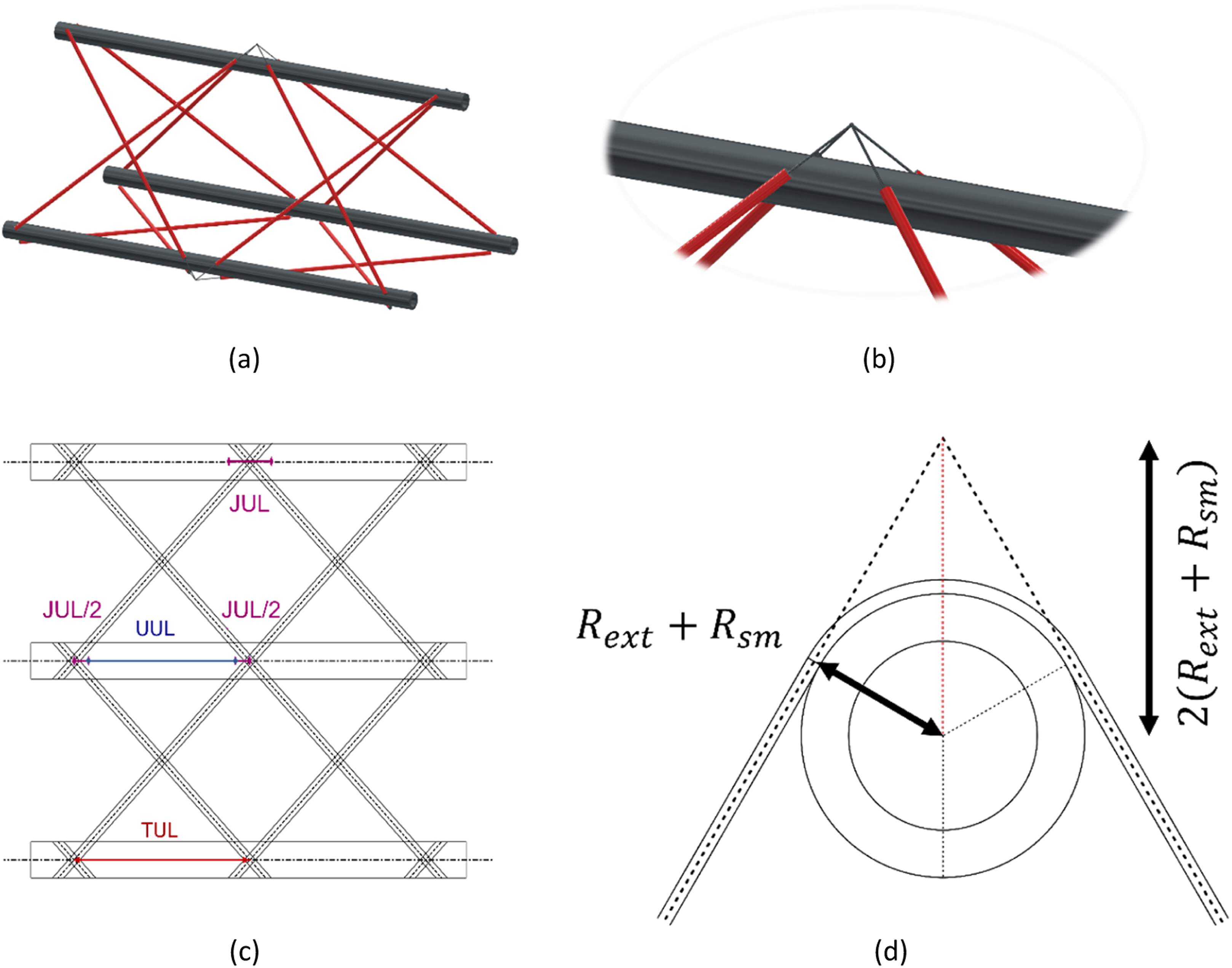
The length of the joint element is found by considering the crossing point of the projected shear web axes as shown by Figure 20 (d). The end point of the joint element can be found at a distance equal to