
Abstract
To investigate and evaluate the effect of void features on the mechanical performance of composite materials, it is important to be able to manufacture samples with a range of controlled void content. A criterion of less than 2% of porosity is typically acceptable for industry. However, it is important to investigate the effect of void content above and below this range, as voids are typically unevenly distributed in composite parts, and so there are likely to be local void concentrations higher than 2% in some sections of the structures. In this paper, a novel manufacturing process that allows panels with a range of void contents to be manufactured in a controlled manner is introduced. This allowed an investigation of the effect of manufacturing parameters, such as time, pressure and temperature and material systems on the void content and morphology of the voids in specimens produced.
Introduction
Voids are a common manufacturing defect in composite materials and can have a detrimental effect on the mechanical performance. Researchers have previously investigated the influence of voids on different mechanical properties, such as interlaminar shear strength1–8 compressive properties9–12 tensile properties13–17 and flexural properties18–22 Mehdikhani et al. 23 provided a very comprehensive review on voids in composite materials, including a discussion of their formation and their effect on mechanical performance. It is important to be able to manufacture samples with voids in a controlled manner so they can be used in further understanding the effects of void features (e.g. shape, size, and quantity) on the failure of composite structures. To achieve this, a study on the use of different process parameters to produce different void features is performed in this paper.
The mechanisms that determine the formation of voids are complex, and depend on many material properties, processing parameters, and geometrical constraints. 24 This makes it challenging to predict the level of porosity in a particular region of a composite part, and even more challenging to predict the distribution, size, shape, and morphology of the voids within that region.
Even so, it is known that voids primarily form in two ways: • Volatiles (such as moisture and solvents) dissolved within the resin during the processing and storage of the resin being released during the cure process; and • Air being trapped during the manufacturing processes when producing the composite.
In the case of volatiles, if the resin pressure drops such that it is below the vapour pressure of the dissolved volatiles within the resin, then the volatiles will be released from the resin and form voids within the composite. 25 The void will then continue to grow until its internal pressure is at equilibrium with the hydrostatic pressure of the resin. It is therefore logical that the quantity of volatiles dissolved within the resin will have an effect on the level of porosity. In fact, Boey and Lye 26 showed that uncured resins stored and exposed to humid conditions for extended periods absorbed moisture from the air, and as a result produced composites with a higher void content.
Boey and Lye 26 also showed that the void content of the final part could be reduced by the application of a high pressure during the cure process, although it was not possible to produce a completely void-free sample. Grunenfelder and Nutt 27 also showed that a high resin pressure helped to suppress the dissolved moisture from forming into voids for both autoclave and vacuum bag manufacturing processes.
Although it has been shown that it is important to apply a high pressure in order to counteract the effect of dissolved moisture, it is also important to apply the pressure early in the cure cycle due to the lower viscosity of the resin in the early stages of the cure cycle. 28
The applied pressure is also important in the reduction of voids caused by entrapped air, as shown by Olivier et al. 29 for two different carbon/epoxy prepreg material systems. Their study also showed that the void shape is affected by the applied pressure, particularly when the maximum pressure is applied when the viscosity is at its lowest. The result is that the voids become more elongated, presumably as they try to evacuate from the material system.
Liu et al. 30 also showed that the timing of the maximum applied pressure is important and that it should be matched to the minimum viscosity of the resin, although this can be countered by increasing the dwell time of the applied pressure if necessary, albeit at the cost of increasing the processing time.
The synergy between the applied pressure and the viscosity of the resin clearly indicates that the temperature of the composite during the cure process is also an important parameter. Hernandez et al. 3 showed that delaying the gelation of the resin (i.e. having a longer processing period) resulted in a lower void content, and that this processing period allowed the voids to evacuate from the system. The low viscosity and long processing period also allowed the remaining voids to elongate along the fibre direction, presumably as a result of trying to escape.
This change in the void shape during the cure process is clearly not instantaneous, as Agius et al. 31 showed by quenching IM7/8552 carbon/epoxy composite samples at different stages of the cure cycle. During the second temperature ramp of this material system, the voids increased in size although the average void content stayed the same. It seems that the increased resin flow during this portion of the cure cycle caused the smaller voids to merge.
In a later study, Hernandez 32 was able to produce samples of very low porosity (<0.2%) by optimising the temperature cycle to maximise the processing period. In addition, it was found that voids tended to cluster in resin rich areas due to being supported by the fibre rich regions that surrounded them. As a result, the pressures on these resin rich areas were reduced and the voids were correspondingly larger.
It is therefore abundantly clear that the cure cycle is very important to the resulting void content. And in fact, in some cases the manufacturers recommended cure cycle is less than ideal when trying to reduce the formation of voids. 33
Whilst the processing parameters are important in controlling the void content of composites, the role of the materials used to make the composite should not be overlooked. For instance, Thorfinnson et al. 34 found that reducing the impregnation of prepreg fibres reduced the porosity, because the dry areas within the prepreg allowed the volatiles and trapped air to escape more easily. Although, if the resin viscosity profile is not carefully tailored then poor impregnation can lead to significant porosity, as the resin is not able to take advantage of the pathways created by the material system. 35
Clearly a balance needs to be struck between an initially viscous resin that allows dry areas to persist and the successful evacuation of air, and a low viscosity resin that allows full impregnation and the avoidance of dry areas in the final part but is more prone to excessive bleeding and void formation.
When there is air trapped within a laminate, the air will try to escape along the path of least resistance, which is generally the fibre direction. However, the distribution of these paths to the edge of the composite are not uniform due to the varying compaction levels through the thickness of the sample. Grunfelder 36 showed that the void content in the middle of the sample is increased as a result of the increased compaction, as the compaction causes a decrease in the permeability in these middle plies.
The provision of air evacuation channels is important in unidirectional laminates, however the challenges are even greater when using woven fabrics as they contain much more space for air to be entrapped. 37 Although the relative contributions to the void content resulting from the material architecture itself and the defects that arise from the stacking sequence are hard to differentiate. 38
Applying this knowledge of void formation, it is possible to create composite samples with specified void contents which can subsequently be used to investigate the effect of voids on the mechanical properties of composites. To effectively investigate the effects, it is important to have as much control over the void content as possible, as well as the distribution, size, and shape of the individual voids. For this purpose, a novel manufacturing process is introduced here, which allows panels with a range of void contents to be manufactured in a controlled manner, and the effect of different processing parameters and material systems to be investigated.
Materials and specimen preparation
Two carbon/epoxy toughened prepreg systems, developed by Hexcel, were investigated: • HexPly® IM7/8552, with a nominal cured ply thickness (CPT) of 0.125 mm; and • HexPly® IMA/M21 with a CPT of 0.184 mm.
In the IM7/8552 carbon fibre/epoxy system a thermoplastic toughening phase is dispersed within the plies throughout the bulk of the resin, whilst in the IMA/M21 carbon fibre/epoxy system an extra layer of thermoplastic particles is dispersed as a distinct ‘interlayer’ between the plies.
There are two types of voids that can be observed in the laminates: • intra-ply voids, which are located within plies; and • inter-ply voids, which appear between plies.
Both types of voids can be inadvertently introduced into composites in the manufacturing process. Furthermore, the particular lay-up is also expected to affect the development of inter-ply voids due to the different interfaces between the plies. The simplest form of multi-directional lay-up was chosen, a cross ply lay-up, as it is expected this will encourage the development of inter-ply voids due to the maximum difference in orientation of adjacent plies.
Each panel of IM7/8552 consisted of 19 unidirectional plies in a symmetric cross-plied layup; whilst for IMA/M21 the total number of unidirectional plies was 11 to achieve a similar overall thickness. The lay-ups were [(0,90)4,0,90,0, (90,0)4] and [(0,90)2,0,90,0, (90,0)2] for IM7/8552 and IMA/M21, respectively, resulting in a single 90° ply at the mid-plane. The plies were cut to a size of 120 mm by 120 mm. The lay-up was undertaken in a clean room following standard lay-up procedures, except that the debulking step (undertaken for 10 minutes at room temperature) was undertaken at the end of the lay-up. This deviates slightly from the standard procedure of debulking every four plies although, due to the panel being thin and flat, the effects were shown to be negligible.
After debulk, the panels were compacted at temperature and cured following a range of different regimes to control the void content, as described in the next section. After manufacturing the panels, samples were cut using a water lubricated diamond cutting wheel to a size of 22 mm long by 10 mm wide. The sample size was chosen for future Short Beam Shear testing. The number of samples cut from each panel varied between 8 and 16. μCT-scanning was able to provide a high-resolution assessment of each sample’s voidage due to their small size. Each scan consisted of analysing four stacked specimens simultaneously as the quality of the scans depends partly on the aspect ratio of the scanned cross section; individual specimens were then ‘separated’ digitally during post-processing.
The scanning was undertaken using a NikonTM XTH320 CT scanner at a source voltage of 55 kV and source current of 140 μA, using four images per projection averaged to reduce the scattering noise; this achieved a scan resolution (voxel size) of 12.6–13 μm. The void content, number of voids, void sizes and morphology were visualized and calculated using the post-processing software VG Studio™ MAX version 2.2 with the porosity analysis plug-in. For post-processing, the 50% threshold was used, as discussed in. 39
Manufacturing process for samples with voids
The manufacturing process is based on that developed by Nixon-Pearson et al. 40 in which the authors investigated the compaction behaviour of laminates. During this work, it was observed that voids were introduced into the laminates prior to compaction, and no changes in the void content occurred for specimens consolidated at room temperature, but that the void content decreased with increasing compaction temperature.
Manufacturing panels with controlled porosity in the current work involved a two-step manufacturing process: (1) Compaction of the samples at a given temperature and pressure (2) Final curing in a hot air oven to ensure the laminates were fully cured.
Compaction of the panels at the chosen temperature and pressure levels was achieved via custom made heater plates that were mounted in an Instron™ testing machine. The heater plates were run through a Carrol&Meynell transformer with a maximum power of 1.5 kVA and controlled by a single-channel Watlow EZ-ZONE PID controller.
The heater plates were heated up to a given temperature, and then the samples were placed between the plates until the samples reached the given temperature. Samples of both material systems were heated up at the same ramp rate. Afterwards, the load was applied at a speed of 5 N/s up to the given value. When the pressure reached the selected value, samples were held under that pressure for a given time and then immediately removed from the heater plates and placed in an oven, preheated to 180°C, for 5 hours to complete the cure for IM7/8552 and 3 hours for IMA/M21. The set-up of the experiment is shown in Figure 1. Experimental set-up for manufacturing panels with controlled void content.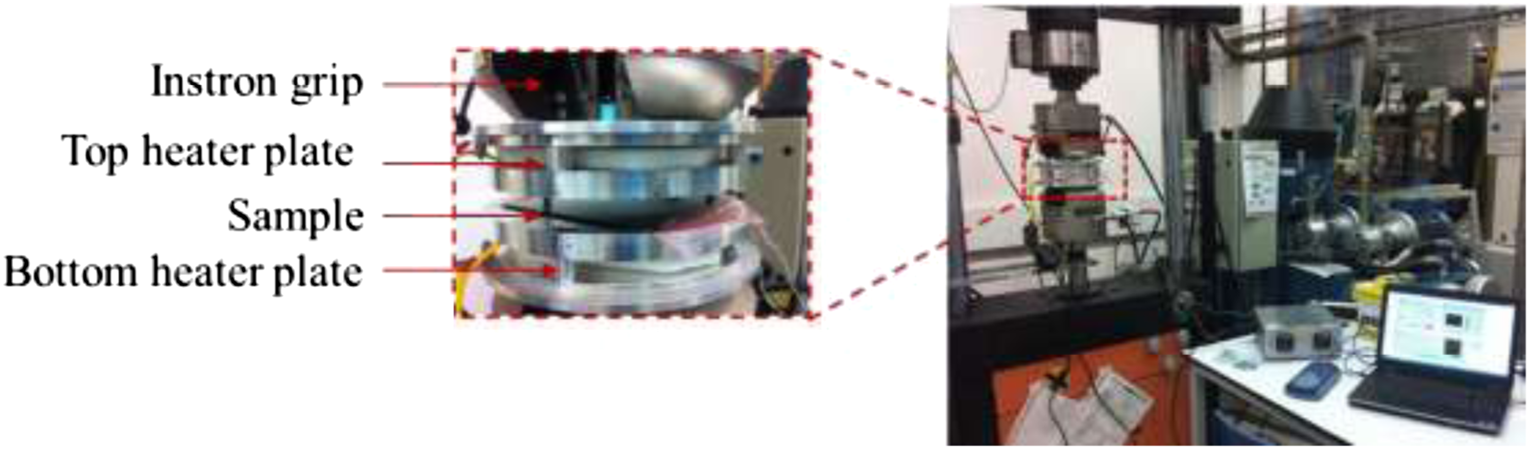
Based on knowledge of void formation found in the literature, several process parameters were varied to investigate their influence on the void content: (i) temperature of the heater plate; (ii) consolidation pressure; and (iii) time of pressure hold. The selected parameters were chosen due to being achievable during the debulk stages of manufacture, or other consolidation processes. Combinations of these variables were tested in order to provide samples having a range of void contents, with it demonstrated herein that an understanding of the effects of these variables allows cured samples with tailored void contents to be manufactured. Furthermore, a comparison of the influence of the same parameters on different material systems has been made.
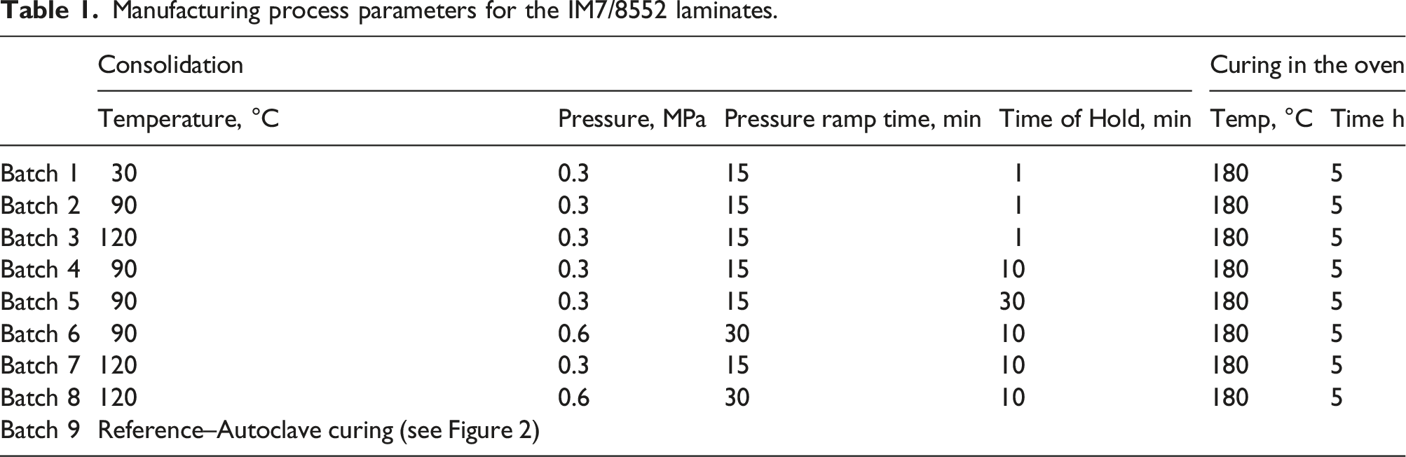
Manufacturing of IM7/8552 panels
Manufacturing process parameters for the IM7/8552 laminates.
Manufacturing of IMA/M21 panels
The manufacturing process used to introduce voids in the IM7/8552 panels was also initially used to introduce voids in the IMA/M21 panels, however the resultant panels possessed an extremely high void content (30–35%). As a result of the toughening particles, the surface of the IMA/M21 prepreg is rougher and less tacky than the IM7/8552, and therefore appears to have increased the amount of air entrapped during the layup process. Furthermore, during the oven cure, the void pressure increases as the temperature rises, which leads to further void formation and expansion. This effect is not counteracted as there is no pressure applied during oven curing to reduce the void content by collapsing the voids. To mitigate this problem, a vacuum pressure was applied during the oven cure, which reduces the average void content within the samples to a level comparable to the upper end of the IM7/8552 panels’ void content (i.e. 8–11%).
Manufacturing process of the IMA/M21 laminates.
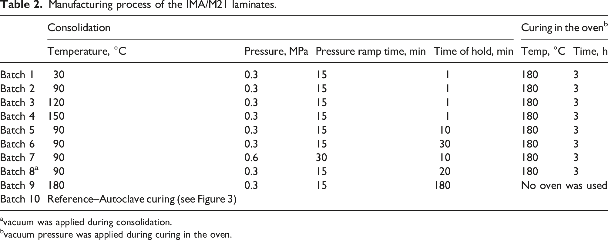
avacuum was applied during consolidation.
bvacuum pressure was applied during curing in the oven.
Average void content in different batches
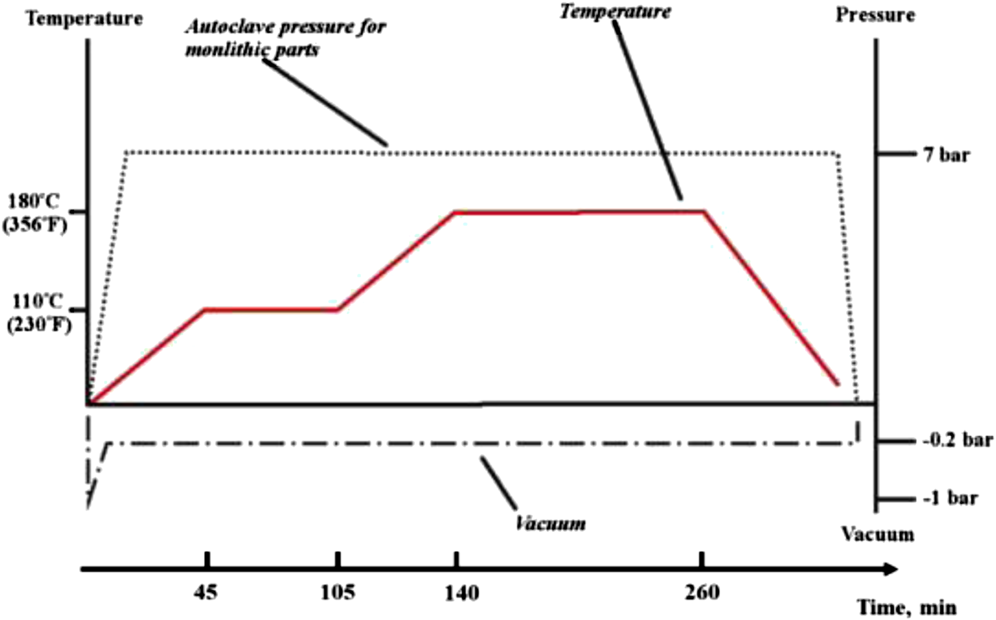
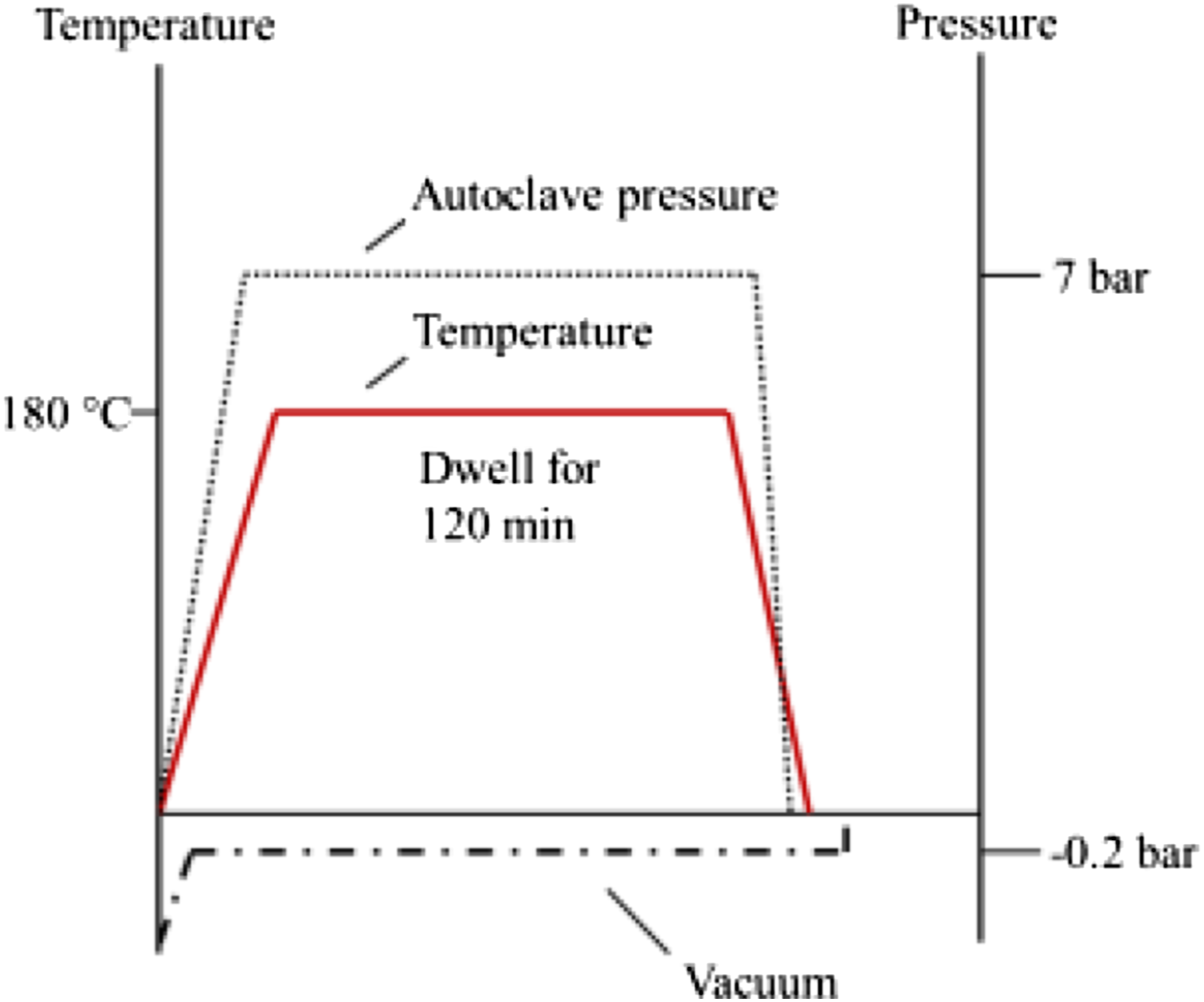
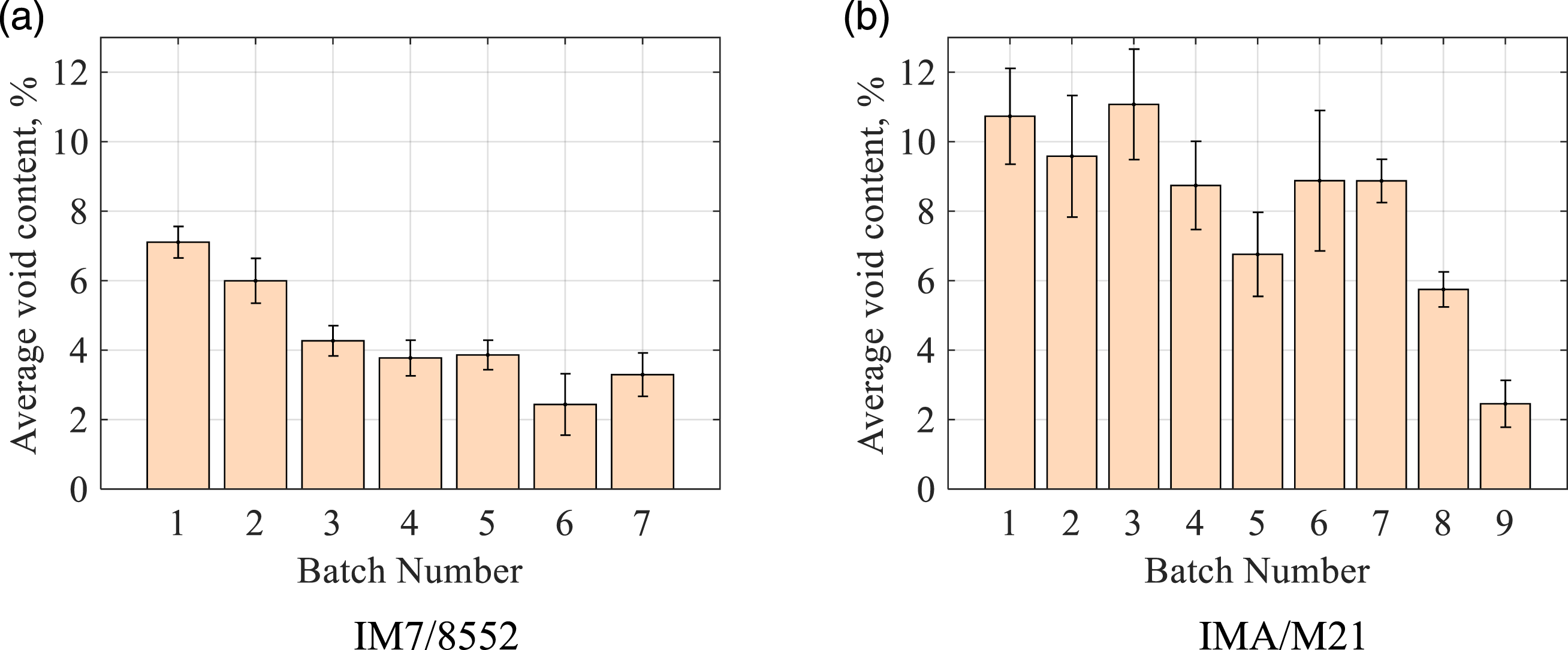
By changing the process parameters, it was possible to vary the average void content, identified by CT scanning, as shown in Figure 4(a) for IM7/8552 and Figure 4(b) for IMA/M21 (note that the entire specimen volume was used to calculate the average void content). Using the same manufacturing process for both material systems resulted in a big difference between IM7/8552 and IMA/M21 in terms of the level of porosity, with IMA/M21 samples having a higher void volume content. Furthermore, the variability in void content within each batch is also greater for IMA/M21. This is likely due to the presence of the interlayer of toughening particles in IMA/M21, which requires a higher applied pressure in order to suppress the trapped air that will otherwise grow into a void when the temperature is increased. Thus, batches 8 and 9 of IMA/M21 have a further refined manufacturing process compared to that used for IM7/8552, in order to reduce the average void content in the panels. Applying additional vacuum pressure during compaction (batch 8) did not significantly affect the reduction of porosity (∼6%), however curing of the panels in the heater plates (batch 9) at a pressure of 0.3 MPa (as opposed to curing the panels in an oven at a vacuum pressure of 0.1 MPa) allowed panels to be produced with an average void content of ∼2.5% (Batch 9). Note, that the measured average void content for the reference batches is 0%. The influence of these process variables on porosity is described in the following sections. Autoclave cure cycle for IM7/8552 panels, as recommended by the manufacturer.
41
Autoclave cure cycle for M21 resin recommended by manufacturer.
42
Effect of process parameters on void content
Effect of the heater plate temperature
It can be expected that the temperature of compaction will affect the average void content of samples due to the decreasing viscosity of the resin at higher temperatures, and therefore increased resin flow. The effect can be most easily investigated by looking at batches 1, 2 and 3 for IM7/8552 and batch 1–4 for IMA/M21, in which all other variables are constant (see Tables 1 and 2). These panels were exposed to the chosen temperature for approximately 16 minutes, consisting of increasing the pressure to the desired pressure of 0.3 MPa (15 minutes) and holding the pressure (1 minute).
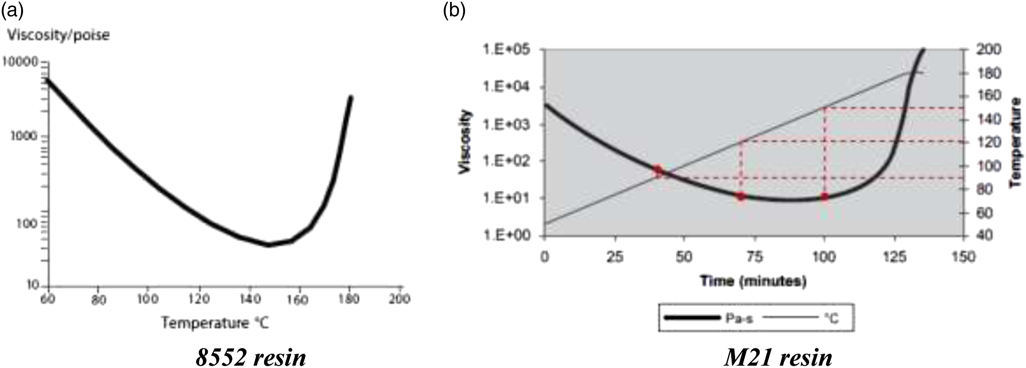
Figure 5(a) shows that the ‘cold’ consolidation of IM7/8552 at 30°C leads to extensive voidage in the panels (around 7%). Increasing the temperature of the heater plates to 120°C decreases the average void content down to around 4%. This is due to the viscosity of the 8552 resin decreasing at higher temperatures, thereby causing it to flow more easily (see the viscosity plot of Figure 6(a), taken from the Hexcel datasheet).
41
It can be suggested that this flow helps any trapped air to escape, hence helping the voidage in the samples to reduce. However, there is still a high level of porosity in all samples, even those samples that have been consolidated at 120°C. This can be explained by the low compaction pressure and time of consolidation at the chosen temperature. Effect of the compaction temperature on the average void content: (a) for IM7/8552 samples; (c) for IMA/M21 samples and on the number of voids (b) for IM7/8552 and (d) IMA/M21 Please note that the y-axis values are different for the respective figures.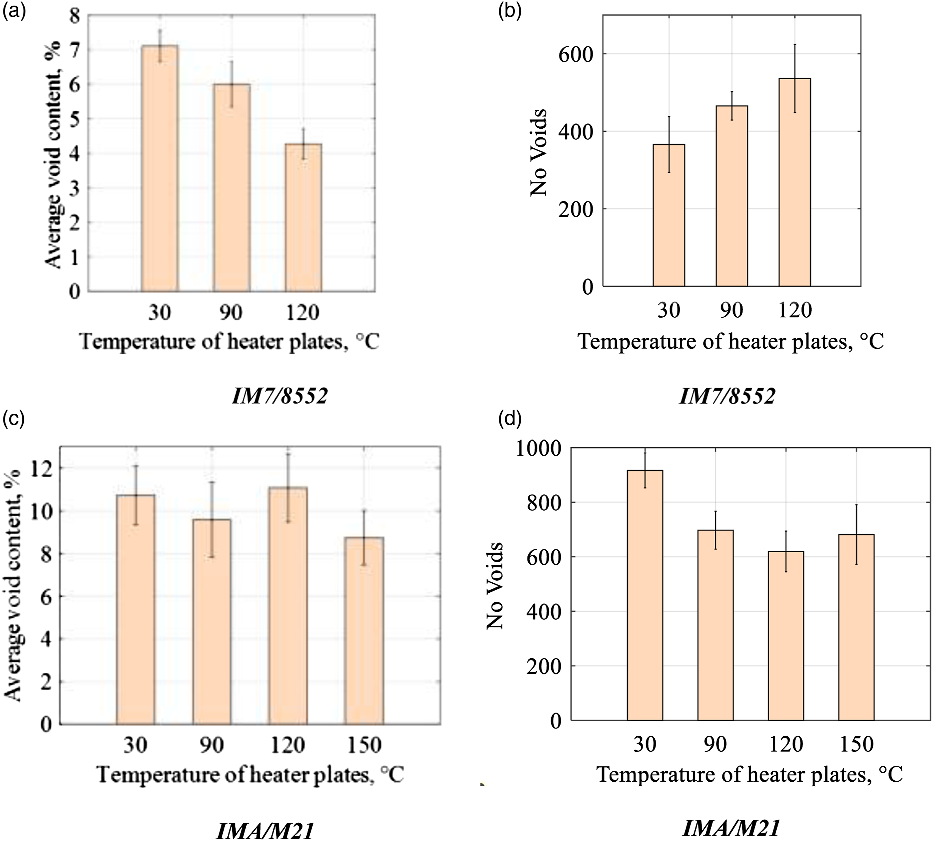
Analysis of the CT-scans using the porosity analysis plug-in of VG Studio™ MAX identified a large number of voids of various sizes in each of the samples. This showed that the number of voids in the IM7/8552 samples generally increased as the temperature of the heater plates increased (Figure 5(b)). The results indicate that cold compaction temperatures tend to introduce larger voids by volume, but smaller quantities of voids in comparison to high compaction temperatures (the average void volume for samples decreasing by 55%, and the average number of voids increasing by 47%, when the compaction temperature is increased from 30°C–120°C). It is presumed that this is due to increased resin flow at higher temperatures, due to the lowered viscosity, allowing trapped air to escape and larger voids to separate into several smaller voids.
The 8552 and M21 resins have different viscosity profiles (see Figures 6(a) and (b)). A rapid decrease of the viscosity with increasing temperature can be observed for the 8552 resin, however the viscosity of IMA/M21 ‘plateaus’ for temperatures between 100°C and 160°C. To take this into account, a further testing temperature of 150°C is investigated for IMA/M21. In this work, viscosity profiles for the 8552 and M21 resin were taken from the manufacturer datasheet, as it has been shown in 43 that the effect of ramp rate on the viscosity of 8552 is negligible up to 150°C, with the same expected for M21.
Figure 5(c) shows the distribution of the void content as the compaction temperature is increased for the IMA/M21 material system. As evident from the error bars, no statistically significant variation in void content is identifiable, showing that this material system (i.e. IMA/M21) is not as sensitive to the temperature of compaction as IM7/8552 over the temperature ranges investigated. Similarly, the number of voids in each sample appears generally insensitive to temperature variation at consolidation temperatures between 90°C and 150°C, although the number of voids is significantly larger at the cold compaction temperature of 30°C (Figure 5(d)), presumably due to a higher viscosity of the resin and the tortuous path created by the toughening particles.
The different behaviour of the two material systems can be understood by noting the viscosity profiles of the respective resins (i.e. 8552 and M21). As previously discussed, Figure 6(a) shows a significant decrease in the viscosity for the 8552 resin as the temperature increases to 120°C, with that decrease being mirrored by the decrease in void content shown in Figure 5(a). In contrast, Figure 6(b) shows a relative ‘plateau’ in the viscosity for temperatures between 100°C and 160°C that could explain the lack of any statistically significant variation in void content. Further testing at 150°C for the IMA/M21 material system gives further confidence to this.
Effect of the consolidation time on average void content
The second parameter of the compaction process that has been investigated is the hold time. As shown previously, the temperature of the heater plates has a significant effect on the average void content for IM7/8552. However, the hold time for those batches was only 1 minute, which is thought to be insufficient to allow air to escape. By increasing the pressure hold time, it was expected that the average void content in the panels would decrease.
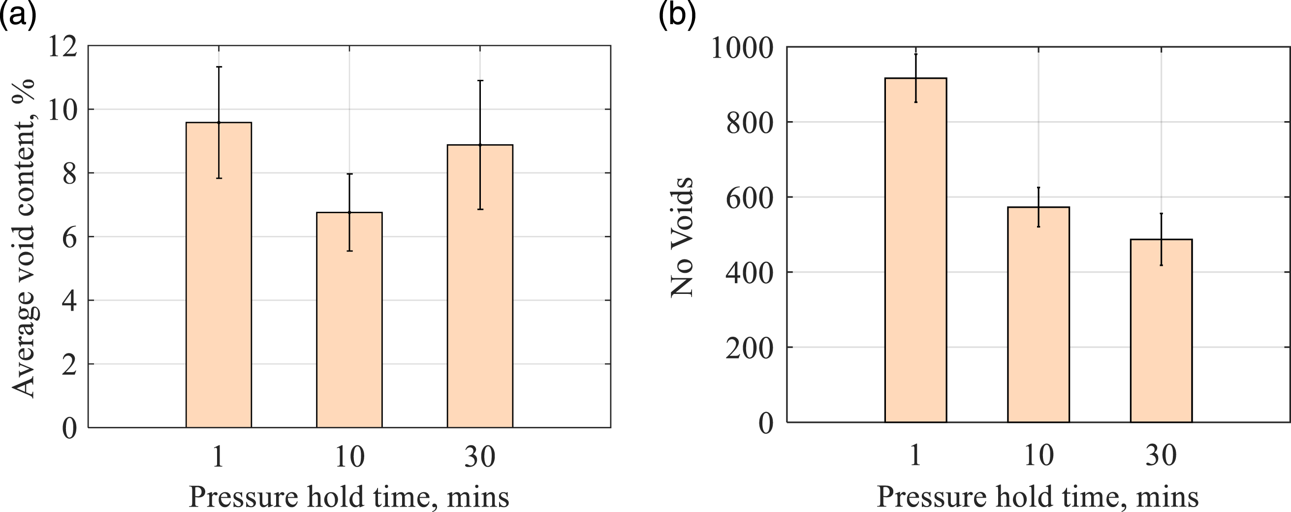
Three panels (batches 2, 4, and 5 with reference to Table 1 and batches 2, 5 and 6 with reference to Table 2) were manufactured using the same compaction temperature (90°C) and pressure (0.3 MPa); however, they were compacted at this pressure for different periods 1 minute, 10 minutes and 30 minutes. The results are shown in Figures 7 and 8 for IM7/8552 and IMA/M21, respectively. Effect of pressure hold time on the average void content and the number of voids respectively at: (a), (b) 90°C and 0.3 MPa and (c), (d) 120°C at 0.3 MPa for IM7/8552. Effect of consolidation time on average void content (a) and the number of voids (b) for IMA/M21.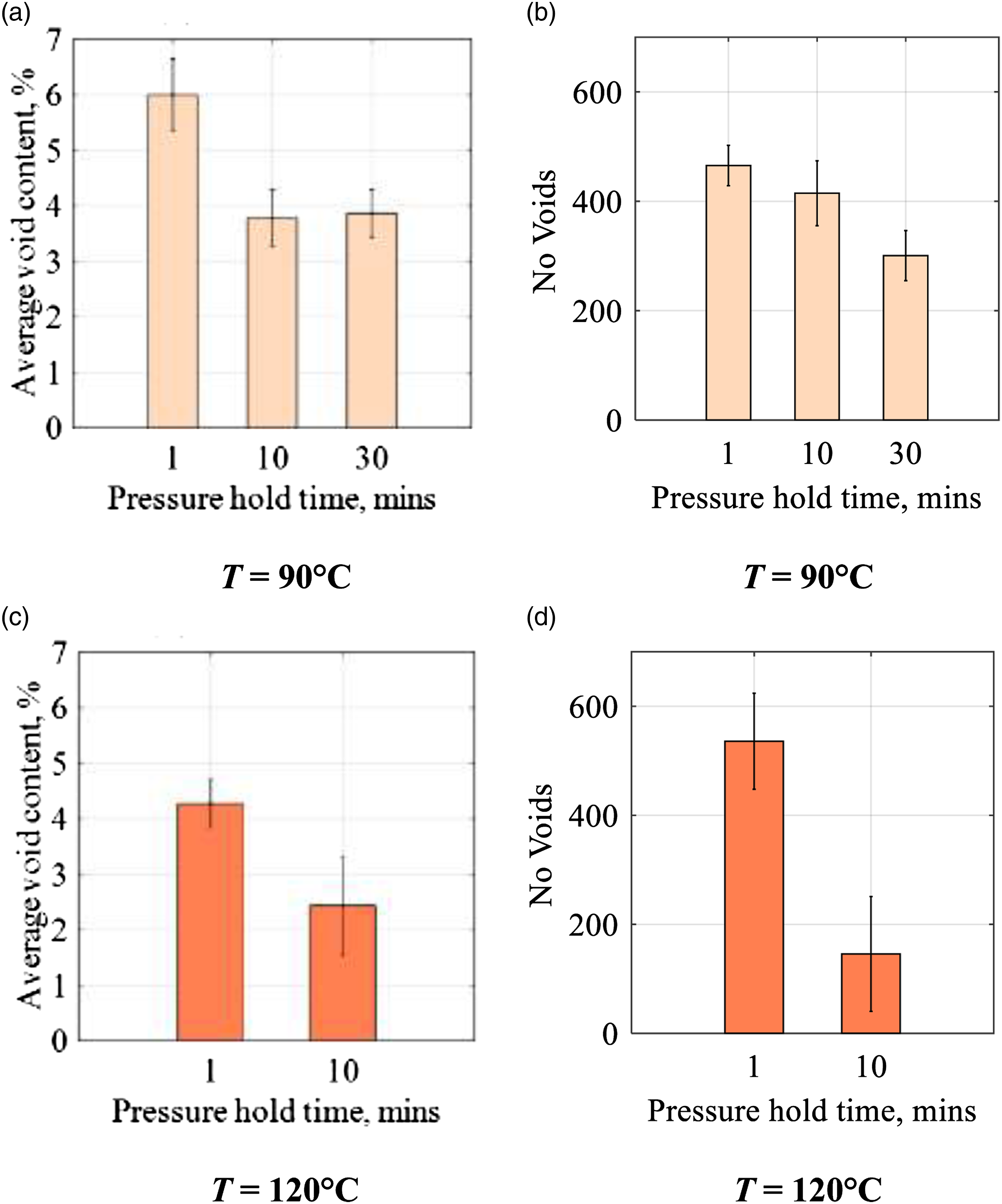
For the IM7/8552 samples, it is observed that increasing the time of compaction up to 10 minutes reduced the average void content by about 40% (Figure 7(a)). However, further consolidation for 30 minutes did not further affect porosity in the panels, which stayed constant at 3.8%. It can be surmised that for these process parameters (i.e. T = 90°C and p = 0.3 MPa) resin flow occurs, which allows trapped air to be squeezed out of the composite panels. At this point a steady state is reached at which the void content is at equilibrium for the given temperature and pressure profile on the panel. The same behaviour was observed for the panel compacted at 120°C (Figure 7(c)), which also achieved a void content reduction of 40% by increasing the time of compaction from 1 minute to 10 minutes. Interestingly, even though a significant reduction in average void content is shown at both 90°C and 120°C when increasing hold time from 1 minute to 10 minutes, at 90°C there is a fairly modest reduction in the number of voids (11%), whilst there is a pronounced reduction in the number of voids at 120°C (73%). This suggests the different resin flow characteristics at 120°C have allowed sufficient flow for the smaller voids to merge into larger ones, with this reflected by the average volume of individual voids increasing by 134% for samples heated to 120°C, whereas at 90°C the average volume of individual voids is found to decrease by 44% when the consolidation time is increased from 1 minute to 10 minutes.
For the IMA/M21 samples, increasing the time that the pressure was held from 1 minute to 10 minutes was found to reduce the void content by 30% (Figure 8(a)), however, perhaps surprisingly, further increase of the consolidation time to 30 minutes resulted in an increase in the void content compared to a consolidation time of 10 minutes.
A clearer trend in the number of voids can be seen for the IMA/M21 material system, with the number of voids decreasing with an increase in the pressure hold time (Figure 8(b)), such that despite samples compacted for 30 minutes having only a slightly reduced average void content to those compacted for 1 minute, the voids in the samples compacted for 30 minutes are on average 21% larger by volume than the voids of the samples compacted for 1 minute.
Effect of the compaction pressure on average void content
The pressure of the compaction process is another significant process parameter that is likely to affect the porosity in composite panels. In this work, in order to introduce voids into the laminates and ‘lock’ them within the panels, a lower pressure than the 0.7 MPa recommended by the manufacturer for autoclave curing was applied, and only during the first step of compaction (not, for instance, during subsequent curing).
To compare the effect of pressure levels on the average void content, two pressure values-0.3 MPa and 0.6 MPa-were investigated.
As expected for IM7/8552 samples heated to 90°C, the average void content decreases with an increase in pressure, such that a reduction of 12% in the void content is achieved (Figure 9(a)). There is a more significant reduction in the average number of voids of 46%, with the resultant average volume of individual voids increasing by 123% as the compaction pressure is increased from 0.3 MPa to 0.6 MPa. Effect of the pressure on the average void content and the number of voids during compaction at: (a), (b) 90°C and (c), (d) 120°C respectively for IM7/8552 (Time of pressure hold is 10 minutes).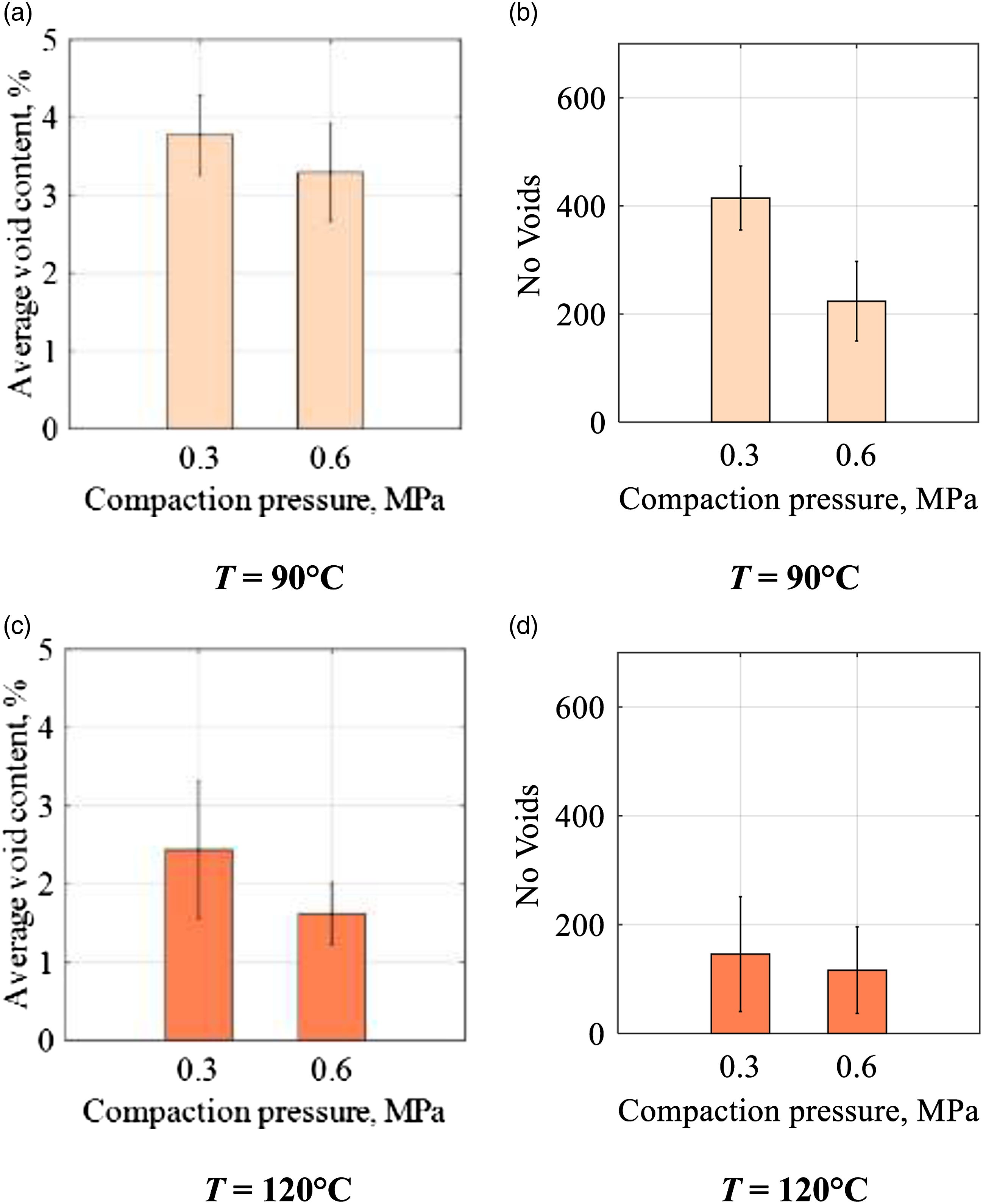
The decrease in void content is more pronounced at the higher temperature of 120°C compared to at 90°C, with Figure 9(c) showing a reduction in porosity of 30%. This is likely due to the higher resin flow caused by the lower viscosity at elevated temperatures. Interestingly, the number of voids for the samples compressed at 120°C remains relatively constant at compaction pressures of 0.3 MPa and 0.6 MPa (Figure 9(d)), with a consequent reduction of 22% in the average volume of individual voids. This disparity between the volume of the voids at each temperature could be explained by a decreased viscosity at 120°C that allows portions of the trapped air forming the voids to more easily escape when the increased compaction pressure of 0.6 MPa is applied.
The effect of the pressure on the IMA/M21 material system is shown to be different to IM7/8552, in that an increase of the compaction pressure led to an increase in porosity within the panels. This is likely due to the increased time required to reach the higher compaction pressure of 0.6 MPa (approximately 30 minutes) in comparison to the compaction pressure of 0.3 MPa (approximately 15 minutes), and therefore the increased time provided to the panel at the hold temperature (i.e. 90°C). In addition, the viscosity of the resin will be lower and as a consequence of this lower viscosity the voids are able to grow larger if sufficient pressure is not applied to collapse them.
25
Furthermore, the higher pressure might also close off gas escape channels and trap the voids within the laminates. Consequently, this has led to a 94% increase in the average volume of individual voids in the samples, with the corresponding reduction in the number of voids (See Figure 10(b)) suggesting that the increased pressure is resulting in voids merging. Effect of compaction pressure on the average void content (a) and the number of voids (b) for IMA/M21 laminates.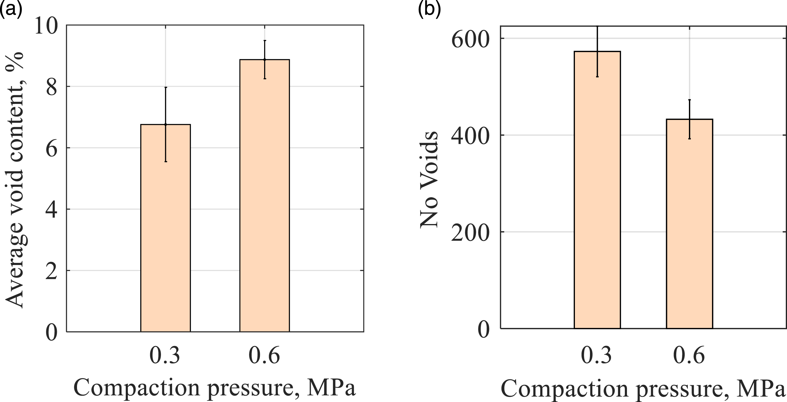
Effect of material system on the void morphology
Different composite material systems, different stacking sequences, and different processing parameters are all likely to affect the distribution, location, shape and size of voids developed during manufacturing. Furthermore, two types of voids can be found in composites: intra-ply voids, that are located within the plies of the laminates, and inter-ply voids, that are located at the interface in-between the plies.
For both material systems IM7/8552 and IMA/M21–, intra-ply voids are needle-like in shape and elongated in the direction of the fibre direction of the plies they are located within (i.e. in the 0°, 90°directions) and have a non-uniform distribution through the thickness of the laminate.
However, inter-ply voids show different characteristics for each material system. For IM7/8552 cross-ply they have the same shape as intra-ply voids, i.e. elongated in the direction of the fibres of one of its adjacent plies, whereas inter-ply voids in IMA/M21 are completely different to those seen in the IM7/8552 laminates, as they tended to be more circular, disc-shaped, and are likely influenced by the pattern of the thermoplastic particles that are located at the interface (see Figure 11). Void morphology for two representative specimens. (a) an IM7/8552 sample with a total void content of 6.37%, and (b) an IMA/M21 sample with a total void content of 9.09%.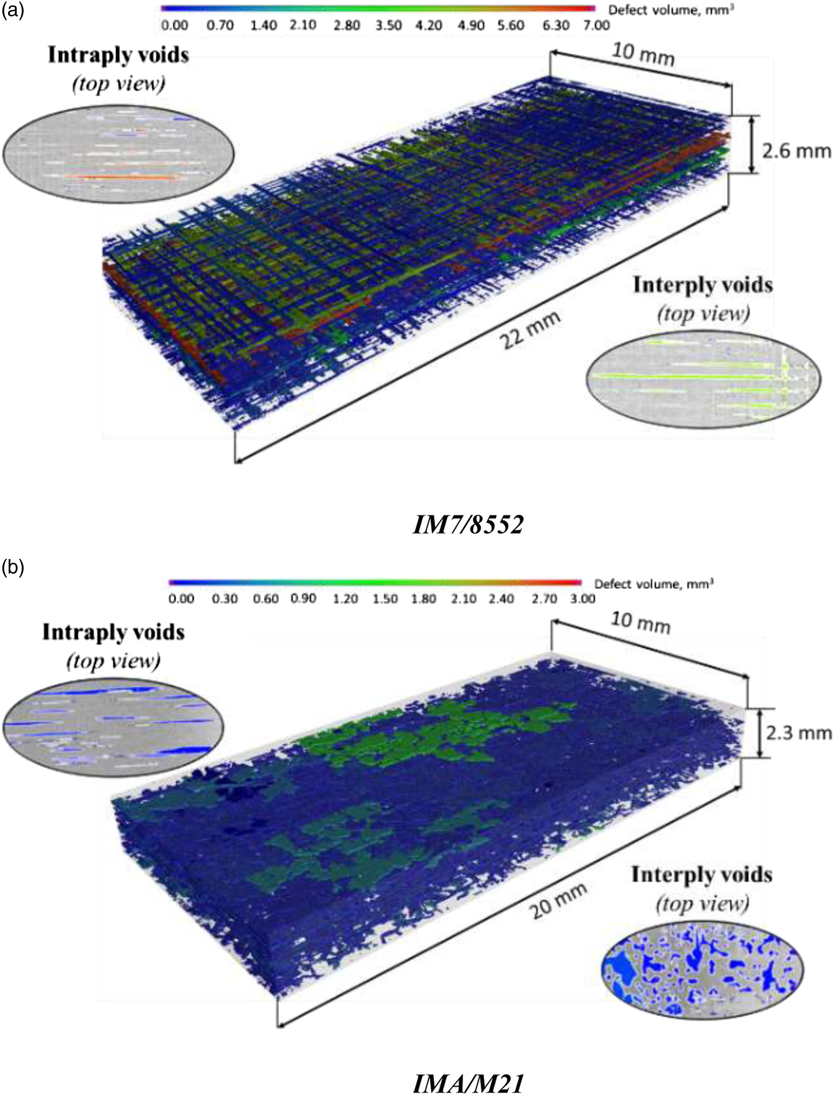
Conclusions
In this paper, it was shown that it is possible to produce samples with different void contents using variations in process parameters, and that the void morphology is influenced by the material system. It is also noted that the different material systems respond differently to similar variations in process parameters. This could be used to create a range of samples to investigate the effect of voids on the mechanical properties of composite materials.
A modified manufacturing technique has been introduced that is able to manufacture composite samples containing controlled levels of voids. Although it is not possible to produce samples with completely uniform void distribution using this method, it is possible to obtain samples with different void contents, different quantities of voids and different void sizes by varying different manufacturing parameters. Three different manufacturing parameters were varied in this research: the temperature of the heater plates, the applied pressure, and the hold time of pressure.
All three parameters have been shown to have a significant effect on the average void content for IM7/8552 cross-ply samples. For instance, it has been shown that with an increase of the temperature of the heater plates from 30°C to 120°C, the average void content decreased from ∼7% to ∼4%. This is presumably due to the increased resin flow of the samples, which could potentially help entrapped air to flow through the resin and escape. Although the increase of temperature decreased the void content in the samples, it did not eliminate voids completely from the laminates. This may be due to an insufficient ‘hold time’ of the applied pressure or insufficient pressure applied to the specimen. It has been shown that increasing the compaction hold time further decreases the average void content. However, it was shown that for hold times above 10 minutes, there were no appreciable benefits. Increasing the compaction pressure also decreased the average void content. However, a combination of all three parameters reduced the average void content most significantly.
The presence of toughening particles in IMA/M21 prepreg samples has been shown to greatly affect both the development of voids and the morphology of voids within the samples, such that the void content is greater and the variability of void content within each panel is increased in comparison with IM7/8552 laminates. It was necessary to apply a vacuum pressure during oven curing in order to counter the increased porosity; otherwise, the average void content was far too high (30–35%), although the void content was still found to be quite high (∼7–12%) when a vacuum pressure was applied. The effect of varying the manufacturing parameters was much less in comparison to that observed in IM7/8552 processing, although some reduction in the void content was observed when increasing the hold time from 1 minute to 10 minutes. However, negative effects (i.e. increasing void content) were observed at longer hold times and higher compaction pressures, and this is thought to be due to viscosity effects in the samples. For instance, the longer hold time of 30 min provides more time for the voids to grow in the absence of sufficient pressure to counteract this. Even when increasing the compaction pressure (from 0.3 MPa to 0.6 MPa) the void content was shown to increase, and this is again suspected to be due to changes in the viscosity, specifically it is thought to be due to the slow application of the load (5 N/s) and the increased time for the sample to reach the compaction pressure of 0.6 MPa compared to a sample at 0.3 MPa. To decrease the void content to ∼2%, a compaction pressure of 0.3 MPa was applied throughout the consolidation and cure process, such that the laminate was cured in the heater plates at 0.3 MPa rather than in an oven at vacuum pressure (i.e. 0.1 MPa).
In terms of the morphology, μCT-scanning of the samples has shown that, whilst intra-ply voids (voids that are located within the plies) are elongated in the direction of the fibres and are mostly unaffected by the material system and laminate lay-up, the inter-ply voids (located at the interface between plies) depend strongly on the particular material system and laminate lay-up. IMA/M21 cross ply inter-ply voids appear to be circular (disc-shaped), whilst IM7/8552 cross-ply inter-ply voids are needle-like shaped and follow the fibre direction of one of the adjacent plies.
Footnotes
Acknowledgements
The authors would like to acknowledge support from Rolls-Royce plc for this research through the Composites University Technology Centre (UTC) at the University of Bristol and from the Engineering and Physical Sciences Research Council (EPSRC) through the Centre for Doctoral Training in Advanced Composites at the University of Bristol (Grant no. EP/L016028/1). Also, thanks to Prof. Robert A. Smith for his valuable insight and discussions on the non-destructive evaluation (NDE) aspects of this work.
Declaration of conflicting interests
The author(s) declared no potential conflicts of interest with respect to the research, authorship, and/or publication of this article.
Funding
The author(s) disclosed receipt of the following financial support for the research, authorship, and/or publication of this article: This work was supported by the 10.13039/501100000266; Engineering and Physical Sciences Research Council; EP/L016028/1.