
Abstract
Spray coating and vacuum-assisted resin infusion processes were implemented in this work to develop multifunctional biocomposite laminates. The biocomposites were fabricated using a bio-based epoxy resin reinforced with natural sisal fibers coated with graphene nanoplatelets (GNPs). A systematic characterization of material properties was performed to evaluate the mechanical, thermomechanical, electrical, and piezoresistive behavior of biocomposites with different GNPs contents (0, 1, 4, 6, and 8 wt.%). The mechanical tests revealed that adding GNPs to biocomposites has a slight positive effect on their flexural properties compared to the neat biocomposites (without GNPs). The electrical and thermomechanical tests showed that the electrical conductivity and glass transition temperature of biocomposites containing GNPs were enhanced significantly, achieving average values of 5.19 x 10⁻⁴ S/m and 63.29°C (26%), respectively. Regarding electromechanical tests, the biocomposites with 8 wt.% GNPs exhibited an excellent piezoresistive behavior under monotonic loading conditions, achieving a gage factor (strain sensitivity) of 3.56. Bending tests with cyclic loading were also performed, and cyclic reproducibility of the piezoresistive response of the biocomposites after 10 cycles was demonstrated, evidencing that the incorporation of GNPs onto sisal fibers by spray-coating produces an effective formation of conductive networks into biocomposites suitable for sensing applications.
Keywords
Introduction
The trend in composite materials is going on in the circular economy, where the overall carbon footprints get to be reduced significantly. Even though the demand on synthetic fiber-reinforced composites (SFRCs) is high-rises in many industrial applications, questions about what to do with their non-degradable waste and the consequent ecological impact are still a primary concern for the scientific community. There are many research studies about SFRC recycling, but it is not cost-effective yet. 1 However, several research opportunities worldwide focus on manufacturing and evaluating natural fiber-reinforced composites (NFRC). The results from these investigations allow visualizing industrial escape routes for the problem of the non-degradable nature of SFRC.2,3
Unfortunately, the mechanical properties of natural fibers are lower than synthetic fibers, with no possibilities to be used for structural applications. Nevertheless, the manufacture of NFRC has attracted significant attention from the scientific and engineering community because of the environmental opportunities of natural fibers. 4 The sisal fiber is one of the most popular natural fibers used for manufacturing NFRC materials due to its availability, relevant mechanical properties (around 350 MPa in tensile strength and 3.8 GPa of 'Young’s modulus), and the viability of manufacturing biolaminates by using bio-based epoxy resins. 5
It is relevant to underline that the biolamiantes term refers to composite laminates where all constituents come from natural resources (natural fibers and bio-based epoxy resins6–8). For instance, Torres-Arellano et al. 6 investigated the mechanical properties of sisal biolaminates and found that their flexural properties exhibit higher strain values. In another work, Torres et al. 7 reported the effect of zinc oxide on fracture behavior of sisal biolaminates finding that peak load in mode I increase as zinc oxide amount raises. Franco-Urquiza et al. 8 reported that using carbonized plant fiber fabrics to fabricate hybrid composites could be an effective route for manufacturing lightweight biocomposites. Nevertheless, mechanical results of sisal fiber-reinforced biobased epoxy resin did not benefit from using these carbonized fibers. Thus, it is essential to develop new strategic routes that allow analyzing the material properties of NFRCs to meet the expectations of industrial applications, and this is the gap this research pretends to cover.
One way to expand the field of application of fiber-reinforced composites (FRCs) is the addition of nanostructures to obtain multifunctional composites. Recently, different carbon nanostructures have been added to the polymer composites to increase their final mechanical and physical properties. Graphene is one of the most interesting carbon nanostructure used as reinforcement element in polymers. Graphene is a special type of carbon-based nanostructure that can be classified into two-dimensional (2D) nanofillers. Graphene nanoplatelets (GNPs) are graphene nanosheets with a crystalline honeycomb structure formed by covalent carbon-carbon bonds. A single graphene layer displays a Young’ ‘s modulus of 1 TPa, the electrical conductivity of 6 × 10⁵ S∙m−1, the thermal conductivity of 5000 W∙m−1 K−1, and a density of 1.9–2.3 g/cm3.9–11 These remarkable and outstanding properties make graphene and graphene-related materials interesting reinforcing nanofillers to provide multifunctional properties to biolaminates without affecting their mechanical performance or increasing weight.
Recent research studies have reported that incorporating graphene-related nanomaterials into the NFRCs improves the biocomposites' mechanical and multifunctional properties. For example, Sarker et al. 12 reported the development of nanoengineered graphene-based natural jute fiber preforms to improve the mechanical properties and performance of jute/epoxy composites. Kamaraj et al. 13 investigated the effect of graphene on the physical and mechanical properties of flax fiber/epoxy composites. In general, graphene’s presence in flax/epoxy composites increases their tensile and flexural strengths and decreases their flammability and water absorption rate. Sadangi et al. 14 showed that adding graphene oxide and functionalized graphene in jute fiber-reinforced composites enhances their bulk properties compared to composites without these nanofillers. Oun et al. 15 studied the effects of elevated temperature on the mechanical properties of flax fiber/epoxy composites containing graphene. Their results showed that adding 0.5 wt.% of graphene improves the composites' flexural strength, modulus and interlaminar shear strength at room temperature. Mohan and Bhattacharyya 16 fabricated natural flax yarns coated with GNPs and characterized their electrical and mechanical properties. The results showed that the coating method improved electrical conductivity due to the incorporation of GNPs to the fiber surface. Regarding the development of multifunctional biocomposites using graphene, limited work has been reported until now, Pereira et al. 17 studied how GNPs may influence the multifunctional properties of natural flax fiber/biopolymer composites and found that the addition of GNPs in biocomposites enhances their electrical conductivity and provides new functionalities to the composites. Other authors, such as Karim et al. 18 have also investigated the multifunctional capabilities of natural fiber-based composites using graphene oxide as nanofillers.
Despite many works that have been performed to investigate the mechanical properties of graphene-based NFRCs, no work has been reported on how GNP content affects the mechanical, thermomechanical, electrical, and piezoresistive properties of natural fiber-reinforced bio-based epoxy resin composites fabricated by spray coating and vacuum-assisted resin infusion processes. This work aims to fabricate multifunctional biolaminates using different GNPs contents and evaluate their effects on the flexural strength, glass transition temperature, electrical conductivity, and piezoresistive behavior of these biocomposites.
Materials and methods
Materials
Graphene nanoplatelets (GNPs) produced by an exfoliation process were used as received and purchased from XG Sciences® (USA). According to the datasheet, GNPs have a particle diameter less than 2 microns and a few nanometers thickness. The natural fiber used in this study was sisal yarns (with thread counts of 35) purchased from Cordeleria, Santa Ines, Yucatan, Mexico. The process used to obtain the sisal fibers was the mechanical extraction, and the configuration of the sisal fibers used for biolaminates manufacturing was a plain weave. 6 The elastic modulus, tensile strength, and density of sisal fibers are 13 GPa, 13 MPa, and 1.12 g/cm3, respectively. The matrix was a bio-based epoxy resin, namely, epoxidized vegetable oil (EVO) Surf Clear with an SD EVO fast hardener from Sicomin Epoxy Systems® (France). This bio-based resin is extracted from vegetable oils with a carbon content of 40%, offering several advantages such as low viscosity, biodegradability, and high functionality. 6
Furthermore, due to its low viscosity, the EVO resin is suitable for manufacturing processes like vacuum-assisted resin infusion (VARI). The solvent that incorporated GNPs onto natural sisal fibers was ethanol from J.T. Baker® (USA). Copper wires were used for electrodes and silver paint (acquired from Ted Pella Inc, USA) as an electrical contact for sample instrumentation.
Characterization techniques
Raman spectroscopy was used to evaluate the structural characteristics of the as-received GNPs. The Raman test was conducted using a Dilor Labram II Micro-Raman spectrometer equipped with a 632.8 nm incident laser light at ambient temperature (∼22°C).
The crystallinity of GNPs was analyzed by X-ray diffraction (DRX) patterns using a Rigaku D/max X-ray diffractometer with a Cu kα radiation range of 5–90°.
The surface morphology of sisal fiber samples with and without GNPs contents was evaluated by scanning electron microscopy (SEM) using a JEOL JSM-6610LV microscope. The sisal fiber surface was coated with gold by the sputtering technique for this analysis. SEM micrographs were taken at 250x and 1000x magnifications for each sample.
Fabrication of biocomposites with GNPs
The sisal fiber biolaminate was manufactured using the VARI process. For the biolaminates fabrication with different GNP contents, a simple method consisting of the combination of the spray coating technique and VARI process was employed, following the sequential steps shown in Figure 1. Four different GNPs contents (1, 4, 6, and 8 wt.%) were considered in this study. First, GNPs were incorporated into sisal fiber sheets by spray coating technique according to previous studies.19,20 The calculated amount of GNPs was first weighed in an analytical balance and placed in a glass vessel. Then, 40 mL ethanol was added to the vessel, and the mixture was sonicated for 30 min (at sequences of 30 s on/off) using an ultrasonic tip. Subsequently, the mixture was sonicated in an ultrasonic bath at room temperature for 30 min. Afterward, the GNP/ethanol solution was spray-coated onto sisal fabrics using an airbrush operated at 45 psi air pressure. After completing the spray coating, sisal fabrics coated with GNPs were dried at room temperature (20–25°C) for 24 h. Two sisal fabrics were placed in stacking sequence [0/90] onto a metal base for the VARI process. The surf EVO resin was mixed with the hardener in a weight proportion of 100:32, and the mixture was manually stirred at low speed. Then, the prepared resin was infused into the bag mold under vacuum to impregnate the sisal fabric layers. The sisal fiber-GNP biolaminate was cured at room temperature for ∼24 h. Once the resin was cured, the specimens for mechanical, thermomechanical, electrical, and piezoresistive tests were cut according to ASTM standards. Spray coating and vacuum assisted resin infusion processes used for preparing the biocomposites with graphene nanoplatelets.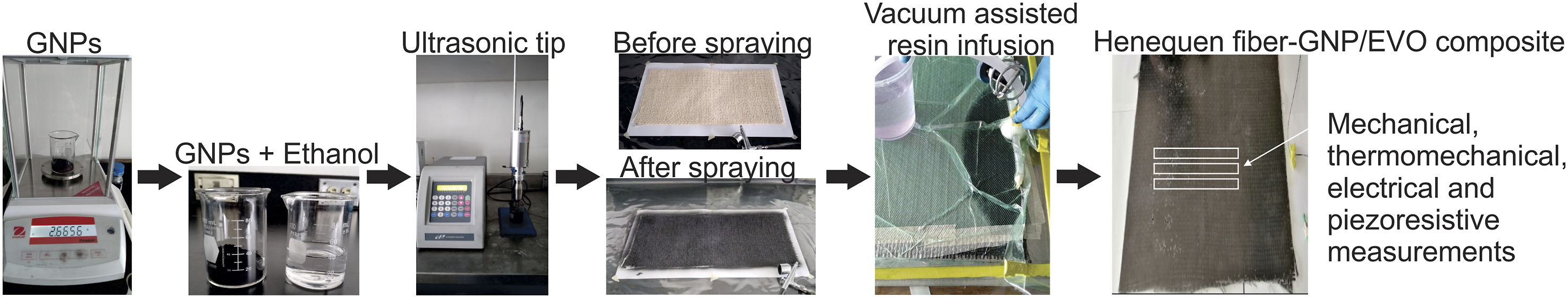
Three-point bending test
Three-point flexural tests were performed on beam-shape specimens of 115 mm long, 13 mm wide, and 3 mm thick to study GNP content’s effect on biocomposites' flexural properties. The flexural tests were performed according to ASTM D7264
21
using an Instron 8872 machine equipped with a 10 kN load cell and a three-point bending fixture. The standard span-to-thickness ratio of the specimen was 16:1, and five specimens were tested. The specimen was placed on the three-point bending fixture and loaded with a crosshead speed of 1 mm/min until failure. Flexural stress
Dynamic mechanical analysis
The viscoelastic behavior of the laminates was evaluated in a Dynamic Mechanical Analyzer TA Instruments DMA Discovery 850, according to the ASTM-D7028. 22 The specimens with the nominal dimensions of 45 mm × 10 mm x 3 mm were tested using the single cantilever geometry to conduct measurements from room temperature to 120°C with a heating ramp of 5°C/min.
Electromechanical test
Electromechanical tests on beam specimens containing 8 wt.% GNPs were conducted by performing three-point bending tests with simultaneous electrical resistance measurements, as shown in Figure 2. A conducting silver paint was used to glue the electrodes on the beam specimen surface to evaluate the piezoresistive effect. The electrical resistance signals (R) were measured on the tensile and compressive sides of the beam specimen using a digital multimeter Agilent 34401A connected to a multiplexer device (see Figure 2). The changes in electrical resistance (ΔR/R0) measured on the tensile and compressive sides of the beam were calculated from R-R0/R0, where R0 is the initial electrical resistance of the sample. For the tensile side, the ΔR/R0 values were measured on the bottom surface of the beam, while for the compressive side, the ΔR/R0 values were measured on its top side. At least three sisal fiber-GNP biolaminate specimens were tested under monotonic and cyclic loading conditions. Photograph of the electromechanical test of a beam specimen under flexural loading.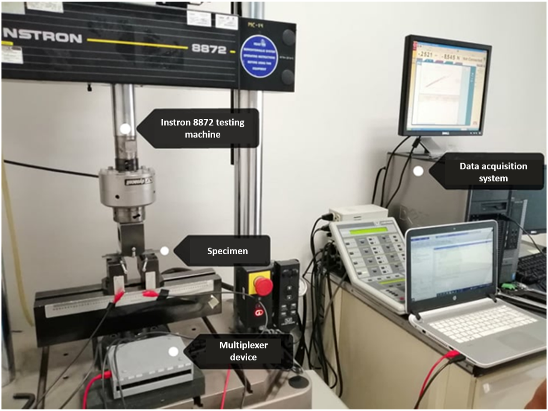
Damage characterization
Failure analysis of biolaminates containing different GNPs contents was performed by SEM using a JEOL JSM-6610LV microscope. For this analysis, tested flexural beams were cut into small samples (20 × 13 × 3 mm3) and then coated with a thin layer of gold by sputtering. SEM images obtained on these samples were taken at 30x and 100x magnifications.
Results and discussion
Characterization of GNPs
Figure 3 reports the spectra of GNPs by X-ray diffraction (Figure 3(a)) and Raman (Figure 3(b)) spectroscopy. As shown in Figure 3(a), a typical diffraction peak is presented at a 2 Characterization of graphene nanoplatelets. (a) XRD patterns, (b) Raman spectrum.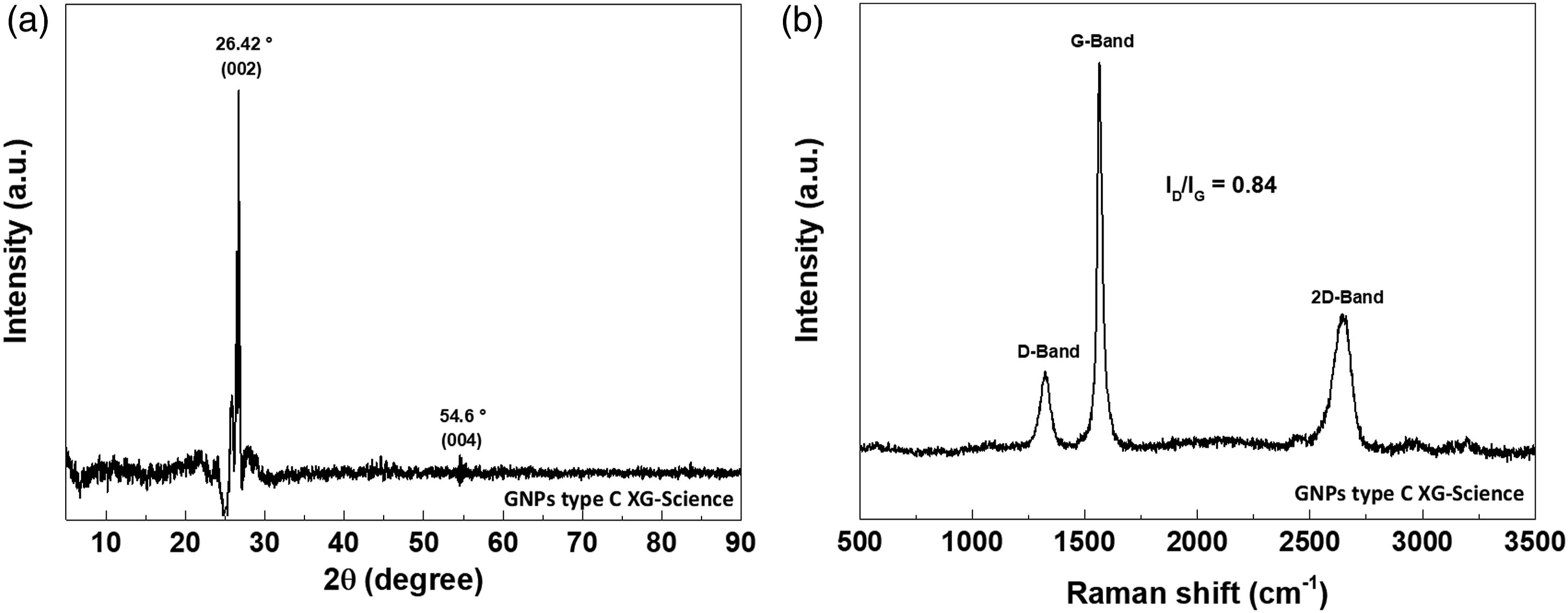
Morphological analysis of sisal fibers spray-coated with GNPs
A scanning electron microscope was used to analyze their morphological surface to observe how the GNPs were dispersed over the sisal fiber surfaces. Figure 4 shows the morphological characterization by SEM of sisal fiber samples spray-coated with GNPs at different weight contents: 0 (Figure 4(a)), 1 (Figure 4(b)), 4 (Figure 4(c)), 6 (Figure 4(d)), and 8 wt.% (Figure 4(e)). The SEM micrographs were taken at 250x (left) and 1000x (right) magnifications. The neat sisal fiber (without GNPs) shows a relatively smooth surface with river marks along the fiber’s length produced by the fibers' mechanical extraction process.
6
In contrast, sisal fibers spray-coated with GNPs (Figure 4(b) to (e)) show a surface with distinct characteristics to the sisal fiber without GNPs (Figure 4(a)) due to the presence of GNPs after coating, which tends to modify the surface morphology from smooth to rough (see Figure 4). In the case of the fiber with the lowest content (1 wt.%) of GNPs (Figure 4(b)), it can be seen that the fiber surface displays the presence of GNPs onto the fiber with rough characteristics but with some zones without GNPs. As the content of GNPs increases (Figure 4(c) to (e)), the SEM images show evidence of a considerable increase of GNPs with agglomerates covering the surface of the sisal fibers completely. This distribution of GNPs on the surface of the sisal fibers can benefit the electrical properties of the biolaminates due to the formation of electrical conductive networks. Scanning electron microscopy micrographs of sisal fibers spray-coated with different graphene nanoplatelets contents. (a) 0 wt.%, (b) 1 wt.%, (c) 4 wt.%, (d) 6 wt.%, (e) 8 wt.%.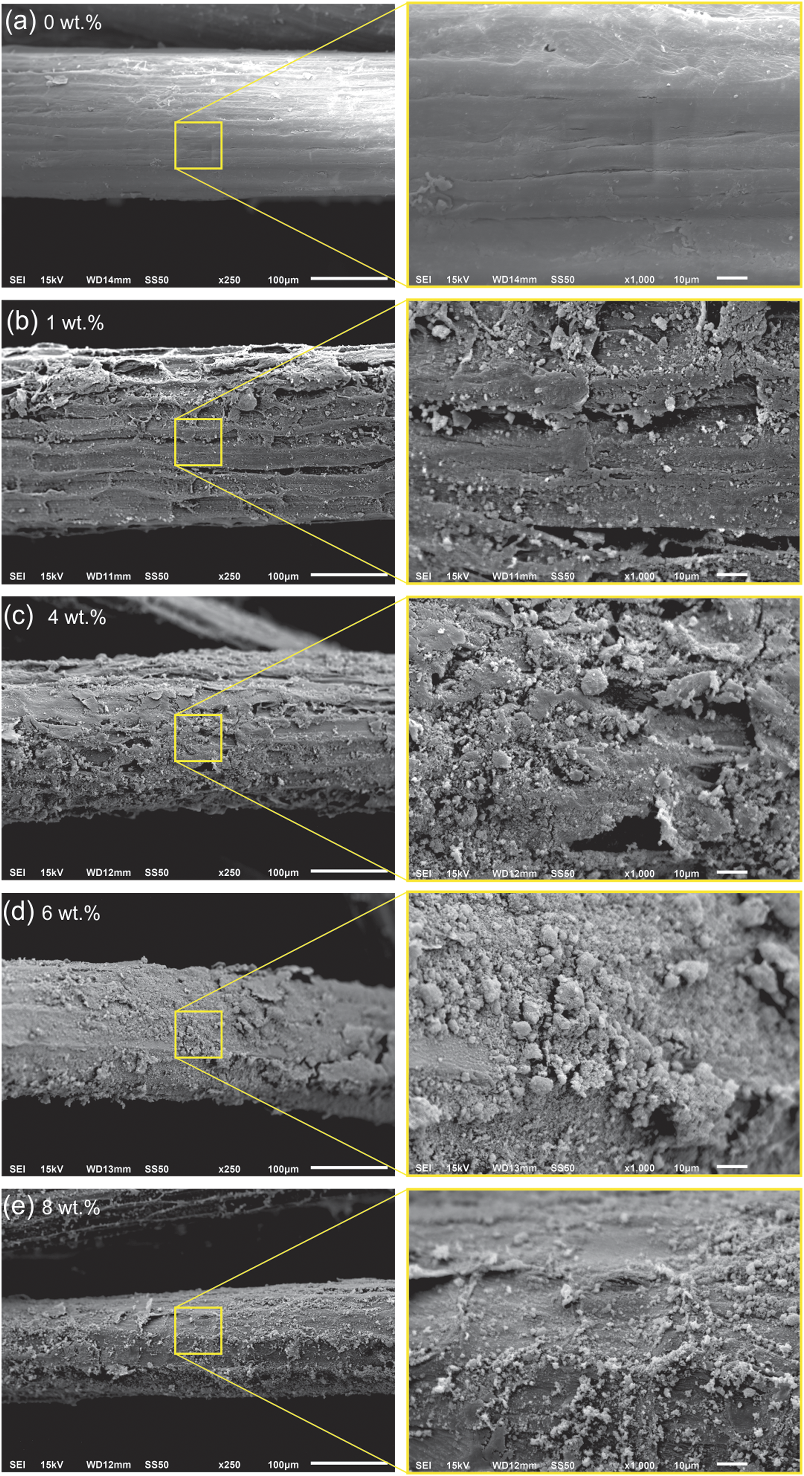
Flexural properties
In order to examine the effect of GNPs concentration on the flexural mechanical properties of biolaminates, the elastic modulus (E) and flexural strength (σ
max
) were measured by the three-point bending test according to ASTM D7264.
21
The results of flexural stress (σ) versus strain (ε) curves of the tested specimens are shown in Figure 5. In this figure, it can be seen that the flexural σ-ε curves of the tested specimens show a fairly linear-elastic behavior at flexural strain values less than 1%, followed by a non-linear response at strain values >1% until reaching the specimen’s failure at strain values greater than 5%. This event varies on each beam due to the GNP concentration incorporated into the biocomposites, see Figure 5(a). It can also be observed that when beam specimens reach their maximum flexural stress (σmax), the stress-strain curves of all biocomposites show a drastic drop in their flexural stress values, as seen in Figure 5(a). The previous behavior can be associated to the final failure of the biolaminates due to the accumulation of damage mechanisms produced after the peak load, as shown in the sequential photographs taken during the flexural test of a specimen until failure (Figure 5(b)). Results of three-point bending tests. (a) Flexural stress-strain curves of sisal fiber/epoxidized vegetable oil biocomposites with and without graphene nanoplatelets, (b) Photographs taken during flexural testing of a specimen until failure.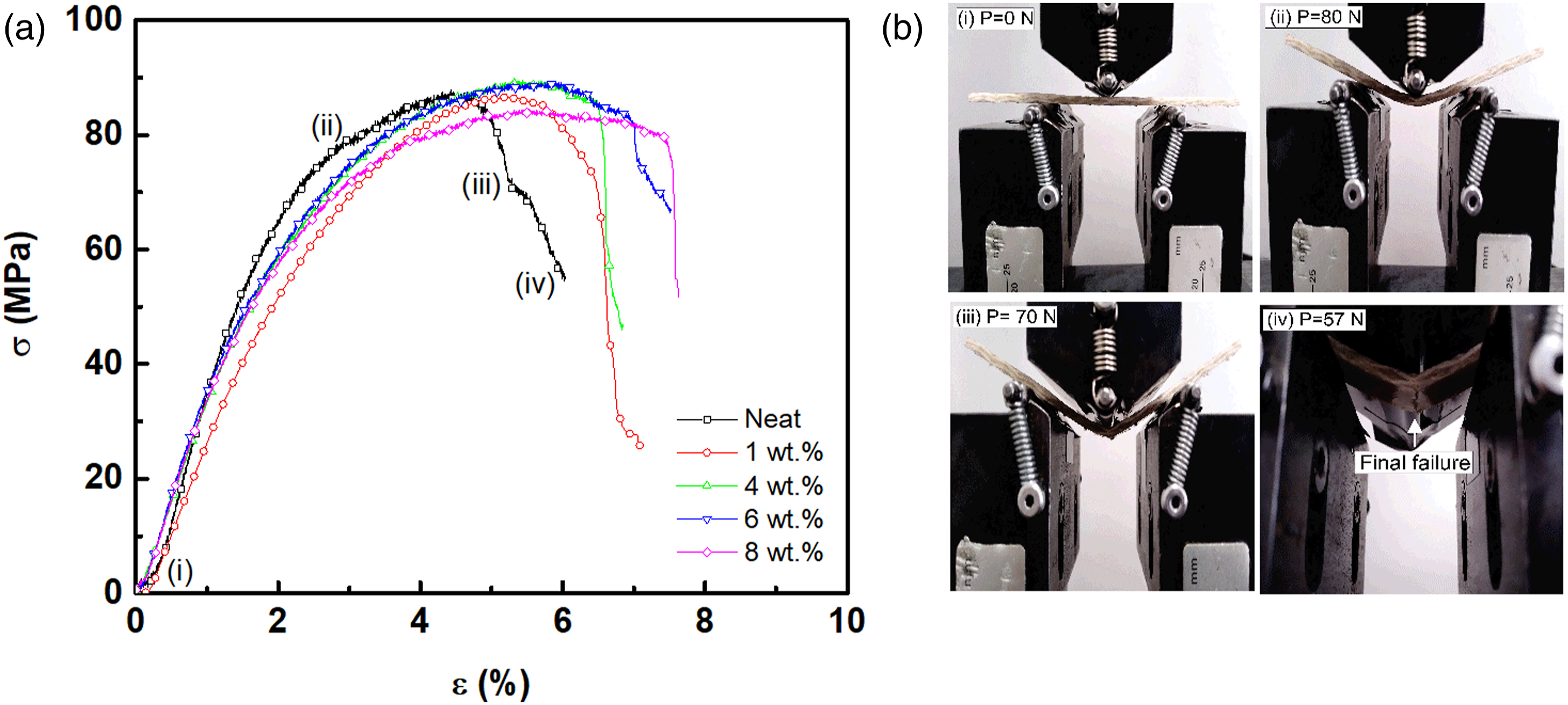
Compared to the neat biocomposites (0 wt.% GNPs), the sudden drop in flexural stress for the stress-strain curves of the biolaminates containing GNPs occurs at higher flexural strain values. Hence, the incorporation of GNPs enhances the failure strain, as shown in Figure 5. Figure 6(a) shows the elastic modulus determined under the tree-point bending configuration for the neat biolaminates and biolaminates containing GNPs. The elastic modulus values were between 3.88 and 3.0 GPa for the neat biocomposite and the biolaminates with GNPs. The highest modulus value was attained in the neat biocomposite (E = 3.88 GPa), while the lowest value was found in the biocomposite with 8 wt.% GNPs, probably due to the agglomeration effect of GNPs. The previous could indicate that the presence of GNPs tends to slightly reduce the stiffness, which is more significant as GNPs concentration increases. Influence of graphene nanoplatelet contents on flexural properties of sisal fiber/epoxidized vegetable oil laminates. (a) Elastic modulus (E), (b) flexural strength (σmax).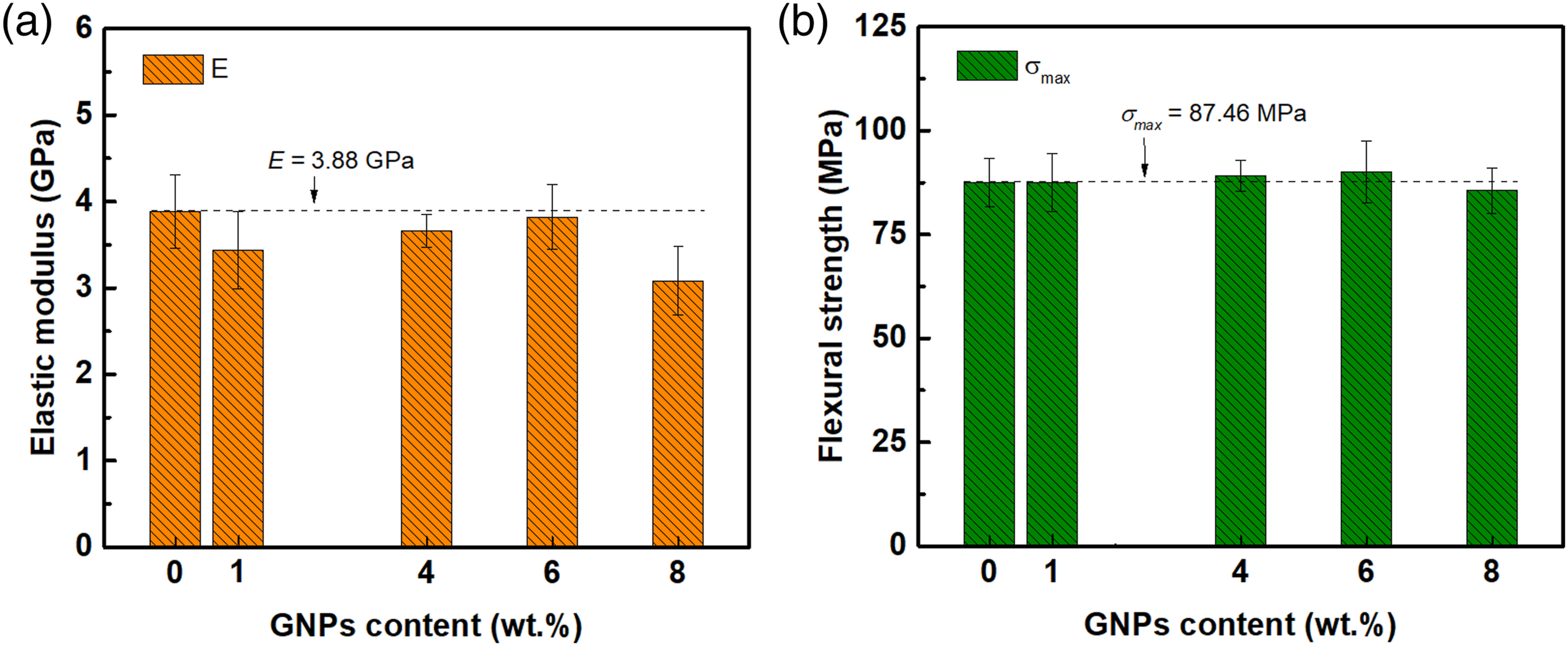
Figure 6(b) reports the average values of flexural strength of the biocomposite specimens with and without GNPs. Overall, it can be seen in the figure that the flexural strength of the biocomposites slightly increases as GNPs contents increase from 1 to 6 wt.%, achieving its maximum value for specimens containing 6 wt.% (87.50 MPa). However, as shown in Figure 6(b), the flexural strength of specimens with 8 wt. % GNPs decreases compared to the flexural strength of the neat biocomposite (87.46 MPa). It is well known that graphene and graphene nanoplatelets (GNPs) have extraordinary mechanical properties and high specific surface area;1,2 however, one of the main issues is their tendency to aggregate and re-stack due to Van der Waals forces of interaction 2 and re-agglomerate due to the lack of functional groups. 3 This tendency implies that a homogeneous dispersion of GNPs is paramount in enhancing composite properties. Therefore, the presence of GNPs agglomerates on sisal fiber fabric surface has an important effect on the mechanical properties of biocomposite laminates, because its formation causes a reduced interfacial interaction with the polymer matrix and hence stress concentrations into composite laminates after their fabrication. Given this context, it can be inferred that the results observed in Figure 6 obey the re-stack and aggregation tendency of GNPs which provokes that elastic modulus tends to decrease compared to the neat biocomposite. Nevertheless, for the case of biocomposites with 6 wt. % GNPs, whose elastic modulus was better with respect to the counterparts (1, 4, and 8 wt.%) but not compared to the neat biocomposite, can be associated with the deposition process of GNPs in composites. Thus, the role of the deposition process is certainly very important to achieve a homogeneous dispersion of GNPs on fibers, thereby improving properties.
The flexural strength remains without significant variations between the neat and the biocomposites containing 1 wt.% NGPs. The previous contrasts with other research work where high concentrations of GNPs affect the mechanical properties of biolaminates due to the agglomeration of graphene that reduces the stress transfer between fiber and polymer matrix.15,13 Despite these results, the strain values of all biolaminates containing GNPs increase notoriously compared to the neat ones, suggesting that the presence of GNPs increases the mechanical performance in terms of strain capability.
Thermomechanical properties
Figure 7 presents the effect of the GNPs on the viscoelastic behavior of biolaminates. Storage modulus (E″) as a function of temperature and the glass transition temperature values are presented in Figures 7(a) and (b), respectively. It is found that the incorporation of GNPs into biocomposites causes a relevant reduction of E″ values. As previously pointed out, GNPs have specific behavior with themselves when there is a high concentration of GNPs per volume fraction due to formation of agglomerates. The higher the nanoplatelets concentration the higher proximity of π-π bonds and wan der Waals forces among the carbon atoms. Thus, it is expected that agglomeration takes place in the material at higher GNP content due to the high surface energy between them. This promotes GNP aggregates increasing the brittleness of the whole composite and decreasing the thermomechanical properties.6–8 Therefore, the leading cause of E” decrease can be associated to agglomeration effect of GNPs because agglomeration restricts the energy dissipation during viscoelastic deformation, which in turn results in a lower peak of loss modulus and declines the E” of biocomposite laminates as shown in Figure 7(c). Results of the dynamic mechanical properties of biocomposites with and without graphene nanoplatelets. (a) Storage modulus, (b) glass transition temperature, (c) loss modulus, (d) tan 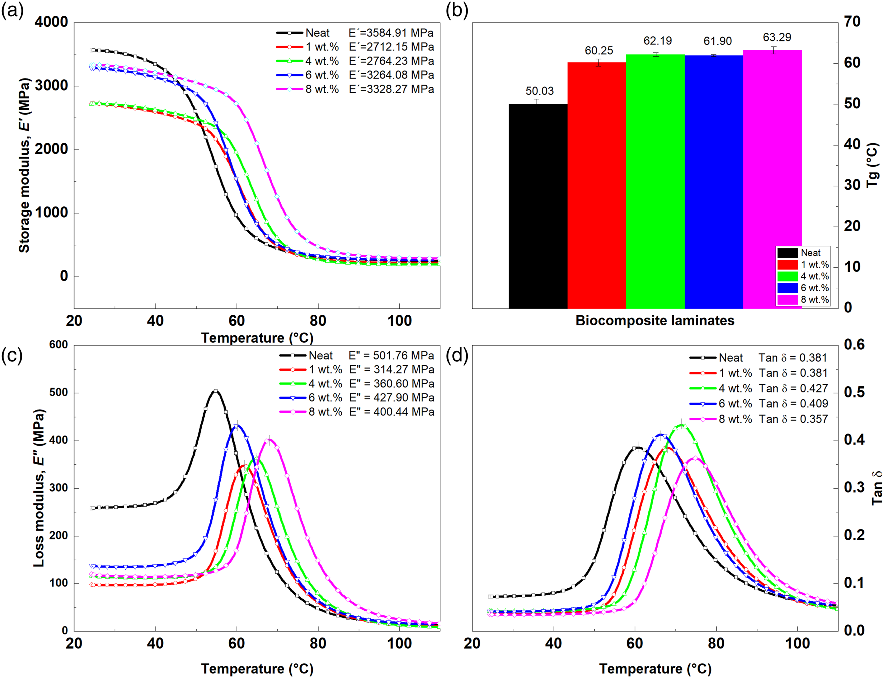
For instance, the E” in the glassy state (E g at 28°C) of biocomposites with 1 wt.% GNPs exhibits a reduction of 24% in comparison to neat biocomposites. The biolaminates with 4, 6, and 8 wt.% GNPs also exhibited reduced E g values by 22, 8, and 6%, respectively. By contrast, biolaminates with GNPs showed significant improvements in their T g values compared to neat ones, see Figure 7(b). Incorporating 1, 4, and 6 wt.% GNP contents into the biocomposites increases the T g values by 20, 24, and 23%, respectively. The DMA results revealed that the T g of biocomposite with 8 wt.% GNPs (63.29°C) was the highest (26.5% increase) compared to the rest of the biocomposites. Therefore, the addition of GNPs into biolaminates favors the increase of Tg values due to the crosslinking and energy dissipation capability between the bio-based epoxy and GNPs. 29
On the other hand, Figures 7(c) and (d) show the loss modulus (E″) and tan δ as a function of the temperature of biocomposites with different GNP contents. Regarding the loss modulus, Figure 7(c) shows that the peak height of E” tends to decrease due to the presence of GNPs in biocomposites. The biolaminate with 1 wt.% GNP content displays the lowest E” value (314.27 MPa), which represents a reduction of 37% compared to the neat biocomposite. Nevertheless, from Figure 7(c) it can be seen that the E″ shifts towards the right side for all biocomposites containing GNPs. A similar trend was also observed for the case of tan δ, indicating that the addition of GNPs has a paramount influence on the thermomechanical properties of biolaminates, which can be explained in terms of the crosslinking degree and interactions between GNPs with the bio-based resin. 29 As can be seen in Figure 7(d), the tan δ curves of biocomposites with 4 and 6 wt.% GNPs display a significant increment in their tan δ peak height compared to neat biocomposites, confirming the changes in crosslinking degree.29,30
Electrical conductivity
The electrical behavior under different GNP contents was studied in this work in order to analyze the effect of GNP addition on the volume electrical conductivity of biocomposites. Figure 8 presents the electrical conductivity of the biocomposites as a function of GNP concentrations (from 1 to 8 wt.%). From Figure 8, it can be seen that the electrical conductivity of biocomposites increases as the GNP contents increase from 1 wt.% to 8 wt.%. In particular, the results in Figure 8 show that adding GNPs at a 6 wt.% content to the biocomposite significantly increased its volume electrical conductivity value, achieving an average value of 5.19 x 10⁻⁴ ± 0.00,005 S/m. This result suggests that the incorporation of GNPs onto sisal fibers produced the formation of effective conductive pathways, leading to higher electrical conductivity. Thus, the GNP concentration significantly affected the electrical conductivity of biocomposites, as reported in Figure 8. As the content of the GNPs increased from 6 wt.% to 8 wt.%, the biocomposite yielded a high electrical conductivity. The increment in the electrical conductivity with this content can be associated with the formation of the percolation threshold, see Figure 8. Therefore, the electrical conductivity of sisal fiber/EVO biocomposites is highly dependent on the GNP concentration, reaching a maximum value at a GNP content <8 wt.% for biocomposites manufactured by spray coating followed by the VARI process. This observation agrees with Pereira et al.,
17
who state that adding GNPs into flax fabric/biopolymer composites increased electrical conductivity values. However, the addition of GNPs directly onto the fibers by spray coating represents a clear advantage over other techniques because it is more viable for manufacturing processes on a large scale. Electrical conductivity of sisal fiber/EVO biocomposites versus graphene nanoplatelets content.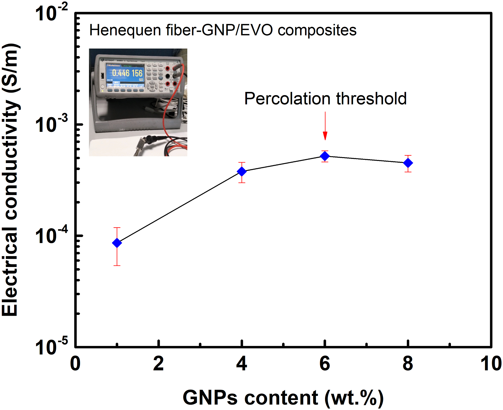
Piezoresistive response of composites under monotonic and cyclic loading
Figure 9 shows the piezoresistive responses employing the electromechanical curves (flexural stress-strain Piezoresistive response of biocomposite specimens with 8wt.% graphene nanoplatelets subjected to flexural loading until specimen failure. (a) Tensile side, (b) compressive side.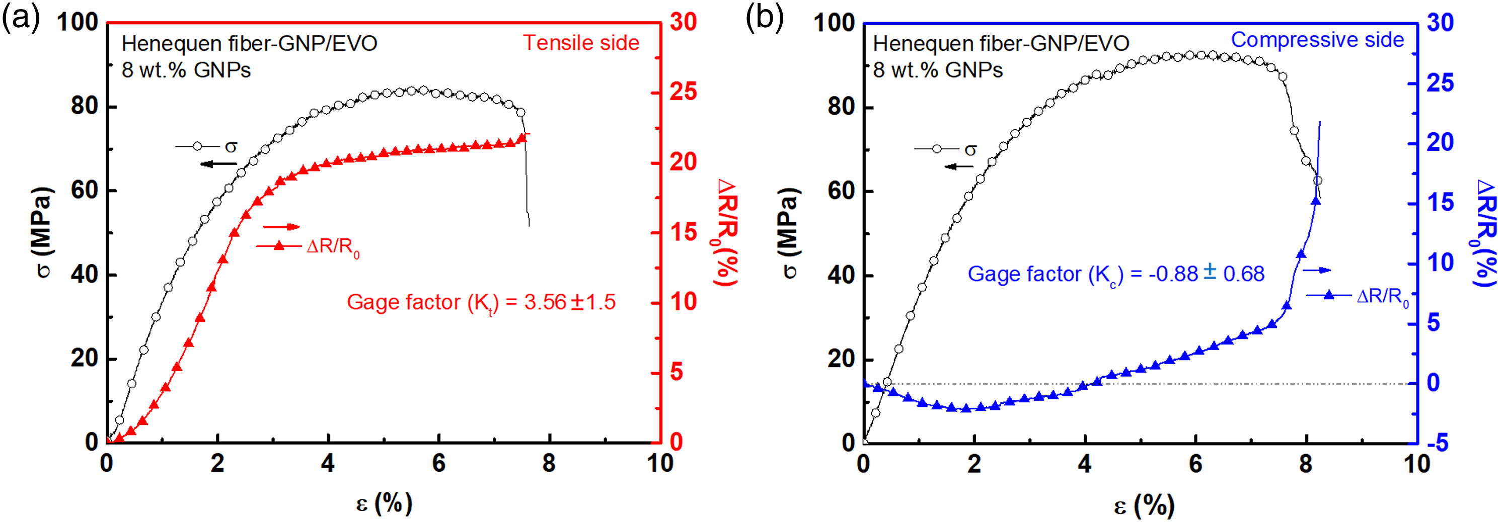
As shown in Figure 9, adding GNPs into biocomposites confirms an excellent piezorresistive effect for the electrical self-sensing capabilities of stress/strain until failure by measuring its in-situ electrical resistance. For this reason, the electromechanical behavior of beam specimens made up of sisal fiber/EVO with GNPs under cyclic flexural loading was also investigated to assess the electrical sensing capability of the GNP's network integrated into the biocomposite. For that purpose, beam specimens with 8 wt.% GNPs content were subjected to 10 cycles of loading and unloading at a flexural load level of 30 N ( Piezoresistive behavior of biocomposite specimens with 8 wt.% graphene nanoplatelets subjected to cyclic flexural loading. (a) Tensile side, (b) compressive side.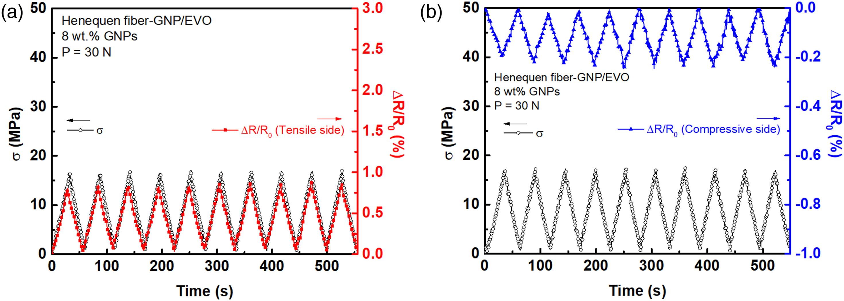
Damage analysis
In order to identify the mechanisms of failure of the sisal fiber biocomposites subjected to flexural loading conditions, SEM was used to analyze the fractured zones of the beam specimens at a microstructural level. In this sense, Figure 11 presents SEM micrographs of the fractured beam specimens of the biocomposites without (Figure 11(a)) and with GNPs (Figure 11(b)–(e)) after flexural testing. Overall, the flexural tensile failure mode was evident for all beam specimens tested in this work (see Figure 11). The SEM images of the biocomposite without GNPs (Figure 11(a)) show that the material failure was of tensile type due to the maximum normal stress located at mid-plane and near the bottom side of the beam. Figure 11(a) also reveals that this failure produced a combination of damage mechanisms associated with matrix cracking, fiber/matrix debonding, and delamination. In addition, the micrographs in Figure 11(a) show that the sisal fibers debonded from the matrix without presenting damage, suggesting a weak interface adhesion between fiber and matrix. The images in Figure 11(b)–(e) also revealed that the type of failure of beam specimens made up of biocomposite with different GNPs contents was flexural tension mode due to bending, which causes a combination of damage mechanisms like matrix cracking, fiber/matrix debonding, fiber pull-out, and delamination. These damage mechanisms can be clearly verified in the SEM images with the help of yellow arrows. From Figure 11(b)–(e), it was noted that some sisal fiber experienced fiber/matrix debonding, which may decrease stress transfer across the interface region. Such damage mechanisms associated with a weak interface and observed in the fractured sections of beam specimens may explain the slight decrease in the mechanical properties of biocomposites (see Figure 6). On the other hand, the fractured zones observed in the beam specimens made up of biocomposites with 4 and 6 wt.% GNPs showed that they experienced a minor degree of damage, which supports the fact that these types of materials exhibit higher flexural strength (Figure 6(b)), as seen in Figures 11(c) and (d). Hence, it can be concluded that the results of SEM analysis indicate that beam specimens based on sisal fiber biocomposites with and without GNPs experience flexural tension failure causing diverse damage mechanisms such as matrix cracking and fiber/matrix interfacial debonding, which can be more severe for the lowest (1 wt.%) and highest (8 wt.%) GNP contents. SEM images of fractured specimens made up of biocomposites with various graphene nanoplatelets content. (a) 0 wt.%, (b) 1 wt.%, (c) 4 wt.%, (d) 6 wt.%, (e) 8 wt.%.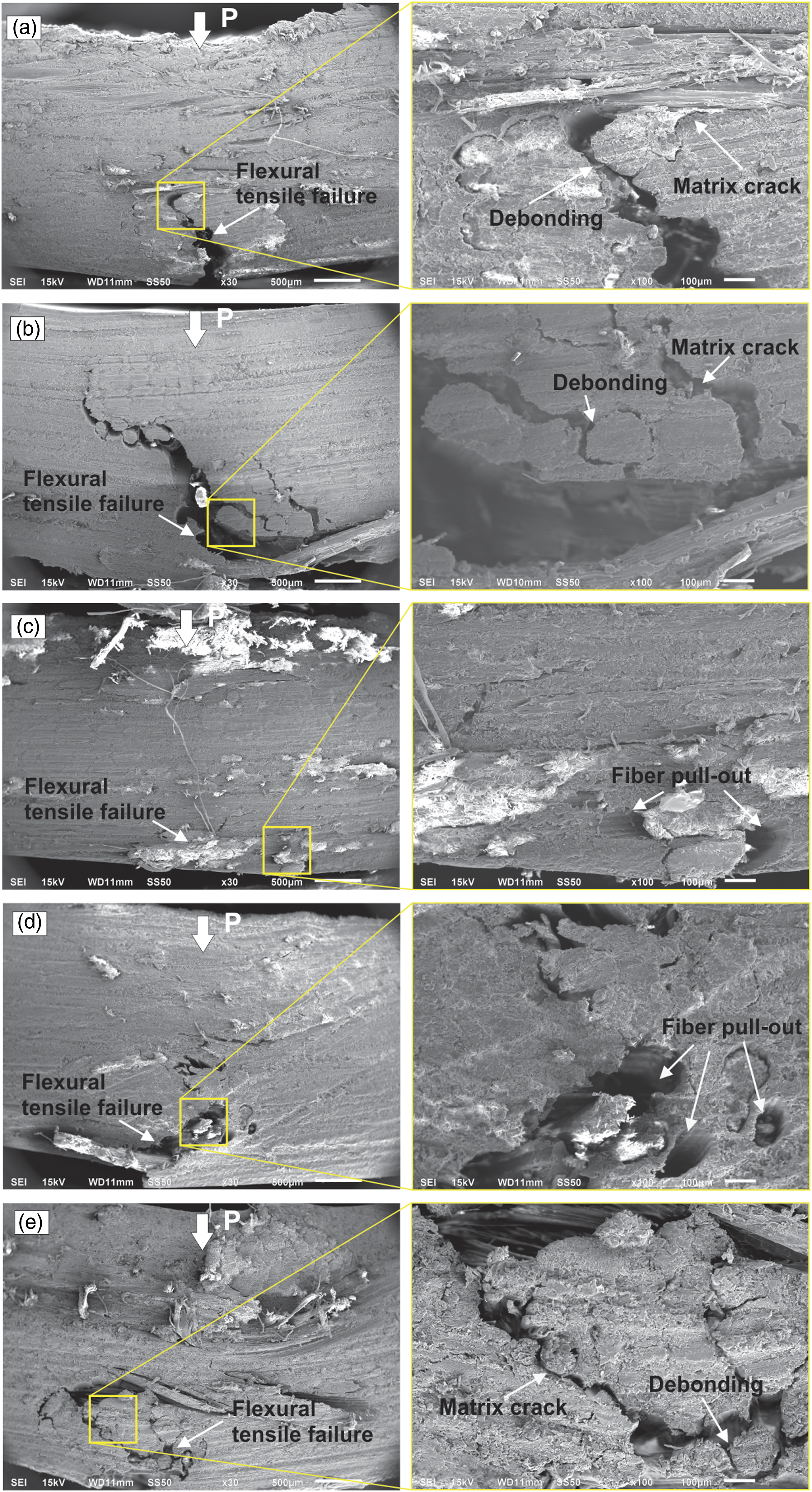
Conclusions
In this study, the spray coating of graphene nanoplatelets (GNPs) has been successfully implemented onto natural sisal fibers at different contents (0, 1, 4, 6, and 8 wt.%) to obtain biolaminates with multifunctional properties. Morphological analysis revealed the presence of GNPs over sisal fiber surface with a relatively homogeneous distribution, confirming that the spray coating is a viable technique to deposit GNPs on natural fibers in a simple and controllable way. The electrical characterization of biocomposites as a function of GNP contents showed a significant increase in electrical conductivity values, obtaining an electrical percolation at 6 wt.% GNPs. This biolaminate also exhibited the highest electrical conductivity (5.19 x 10⁻⁴ S/m).
The mechanical properties of biocomposites with GNPs showed that the elastic modulus and flexural strength were not improved by incorporating GNPs but they were not affected significantly. However, the presence of GNPs improved the strain values as compared to the neat biolaminate.
DMA characterization revealed that incorporating the GNPs into biocomposites resulted in a significant increase in the glass transition temperature from 50.03°C to 63.29°C for biocomposites with 8 wt.% GNPs. This effect also benefited the rest of biolaminates containing GNPs, rendering up to 15% increments. Fractographic evaluation performed by SEM showed that the type of failure of tested specimens was mainly produced by a flexural tensile mode dominated by normal stresses at the bottom surface of the beam, which induces damage mechanisms associated with matrix cracking, fiber pull-out, fiber/matrix debonding and delamination.
Piezoresistive tests of biocomposites with 8 wt.% GNPs under monotonic flexural loading showed that their relative change of electrical resistance matched satisfactorily with flexural stress-strain behavior. The gage factor of biocomposite laminates obtained from the flexural electromechanical test was 3.56. It was also observed that the relationship between stress and relative change of electrical resistance was linear, and the piezoresistive curves exhibit a slight increase in their values when material failure occurs due to disruptions of the electrical networks produced into biocomposite. The electromechanical tests under cyclic flexural loading revealed that the response of the biocomposite’s relative changes in electrical resistance follows the loading-unloading cycles' response during all the applied cycles without changing their stability and amplitude, confirming its capability for structural health monitoring applications.
Footnotes
Acknowledgements
We express our acknowledgment to M.Sc. Antonio Banderas for the SEM technical support.
Declaration of conflicting interests
The author(s) declared no potential conflicts of interest with respect to the research, authorship, and/or publication of this article.
Funding
The author(s) disclosed receipt of the following financial support for the research, authorship, and/or publication of this article: This study was funded by the National Council for Science and Technology (CONACYT) of Mexico through the SEP-CONACYT program with grant number CB-2015-01-257458.