
Abstract
The wind, stochastic in nature, is one of the fastest-growing and most promising renewable energy resources in the entire world. Thus, this paper investigates the influence of parameter uncertainties upon a dynamic performance of a grid-tied Doubly-Fed Induction Generator (DFIG)-based Wind Energy Conversion System (WECS). The main uncertain parameters found in the study are mutual and rotor winding reactances which occurred due to the variation of the angular positions of the rotor caused by varying wind speeds. The variation in the wind speed caused the generator rotor speed to deviate between 25% and 150%. Consequently, the rotor winding reactance of DFIG changes from its nominal value of 1.31 mΩ to between 0.983 and −0.655 mΩ; and the mutual reactance from its nominal value of 0.941 Ω to between 0.758 and −0.4708 Ω. As a result, the stator and rotor winding voltages and currents of the DFIG are uncertain.
Introduction
Wind Energy is an abundantly available and globally recognized resource of renewable energy. Among the generators and types of wind turbines used for energy conversion using wind turbines, the Doubly-Fed Induction Generator (DFIG)-based system is the most widely used one.
This mechanism of electromechanical energy conversion from the wind via an aerodynamic system is stochastic due to the frequent variation of wind speed. This in turn affects the mathematical model of the plant (DFIG in this case). Unless and otherwise, the proper control strategy is applied, the stability of the entire networked system can be affected. For instance, if phenomena on the variations of load demand, short circuit of a transmission line, loss of communication line between two systems, loss of synchronized mode, and change of generator rotor angle cause increasing and uncontrollable changes in voltage and frequency, which causes system instability and hence results in poor power quality (Kundur and Malik, 2022; Machowski et al., 2020). For this and related reasons, mathematical modeling of the system is very important. It is quite observable that, the performance characteristics of DFIG-based wind energy conversion systems (WECS) are mainly dependent on the mode of operations (super synchronous, and sub-synchronous) resulting from wind speed variations.
The work carried out by Zahra et al. (2020) focuses on the mutual inductance uncertainties of DFIG in wind turbine systems under symmetrical triple line (LLL) fault scenarios. It is well evidenced that the varying unknown parameters are the main causes for uncertainties in the WECS model with the neglection of wind speed variation with nonlinearities. Furthermore, it is shown by the work of Yan et al. (2019) that the dependence on wind turbines is related to aerodynamics, structural flexibility, tear, and wear. Under consideration and the existence of the aforementioned factors, the uncertainties of wind turbine models get further boosted. As a result, the stability of a given power system has to be disturbed and hence the overall performance of the grid-tied wind turbine system is weakened apart from the reduced lifetime of the power plant.
The authors Benzaouia et al. (2020), Jalal and Ganjefar (2019), Li et al. (2019), Rezaei et al. (2019) carried their work by modeling a conventional Permanent Magnetic Synchronous Generator (PMSG)-based wind turbine system to estimate and control the generator rotor speed and its output power while Srikanth and Thirumalaivasan (2022) presents a grid tied-DFIG model for the same purpose. Similarly, the author of Haile et al. (2021), Tuka (2023), Tuka and Endale (2023)estimated the model of the same machine by taking the relationship between generator rotor speed with the speed of the wind under dynamic conditions. On the other hand, a mathematical model of a DFIG-based wind turbine using Model Predictive Control is depicted in detail by Alfeu (2022). Based on the above and other related analyses, we came to see that parameter uncertainties in the model with its effect on the performance of the power plant are not well considered in any of the aforementioned literature.
The effect of uncertainty of parameters using rational fractional representation upon the stability of a grid-connected power system with wind turbines is presented in Shi et al. (2018). For this study, the authors have assumed the damping factor, inertia constant, and controller parameters uncertainties by addressing active power or frequency stability. Nevertheless, what is missed in this work is the main source of uncertainty problems. Even though the work shown in Yayla et al. (2018) brought matched and unmatched uncertainties of model parameters, unluckily, there has been no significant analysis seen on the performance of the existing system. An uncertainty analysis taking consideration of the vibration of a tower, friction, and varying nature of wind speeds is being analyzed in Alok et al. (2022) for a Variable Speed Wind Turbines (VSWT) system. For this purpose, the paper has implemented a nonlinear feedback control technique to see the robustness of the VSWT system. Contrary to the study, there had been no consideration of the type of generator used and parameters that are uncertain enough to affect the performance of the entire system. The direct and quadrature axis PMSG inductances of the stator are presented in Yan et al. (2021b). Even though the paper has tried to address important concepts, there is a lack of description of the effect of inductances on the performance of the power plant.
Interestingly, the various techniques to be used to reduce and quantify uncertainties using a numerical approach via developing a model for a wind turbine are described in Crépey et al. (2020) and Hirvoas et al. (2021). Mainly, the authors have approached global sensitivity analysis by the use of recursive Bayesian inference methods. In their way, they applied the former technique for uncertainties quantification like the intensity of turbulence and average wind speed which are appearing in the input parameters of the wind turbine. On the other hand, for the case of identifying uncertainties occurring as to the fatiguing nature of wind turbines, blade Rayleigh damping, the thickness of the tower, and stiffness of the drive train system, the Bayesian inference framework is employed. The work seen by the mentioned authors has given due attention to the mechanical structure of the wind turbine lacking the effect analysis on the overall performance of the WECS that might occur as of uncertainties.
Taking consideration of the direction of wind and misalignment of the yaw system along with model uncertainties is done in the wind farm by applying yaw control set-point optimization. In this regard, emphasizing the modeling of the wake effect under uncertainties of the condition of wind parameters to capture maximum power from the wind at varying atmospheric conditions is carried out by Michael (2021). Modeling the wind turbine system by taking the perturbed pitch angle of the blade with the speed of wind about the generator rotor speed is described by Ravikumar and Saraswathi (2020). In this article, the two authors emphasized the control approach of the generator rotor speed while the effects of uncertainties toward the improvement of power output are lacking. The various classifications of uncertainty for optimization in the hybrid energy system are given by Fan et al. (2022). In their study, they classified it into five categories. However, they have given more emphasis to the uncertainty of sporadic new energy power generation, and uncertainty in the operating state of equipment and system of the WECS. In their analysis, it evidenced that the power output from the wind turbine is simply affected by uncertainties issues, but the failure of equipment in WECS is another major issue of uncertainty in the modeling aspects. As per the study carried out by Yadav and Saravanan (2022), the dynamic performance of WECS can be reduced by affecting its stability in cases of parameter uncertainty of the grid-tied power system. Variations in wind speeds are also one of the factors that are affecting the performance of the system.
The imbalance of generation and load is the most important reason for voltage and frequency instability that can again affect the quality of power. The dynamic performance of the system controller determines the quality of the power supply according to frequency and voltage. Conventional controllers having a fixed constant efficiency shows a weak unstable response in front of the increase of strong fluctuations (Solberg, 2012). A detailed summary of the review of works of the state of the art is presented in Table 1.
Summary of review of the state of the art.
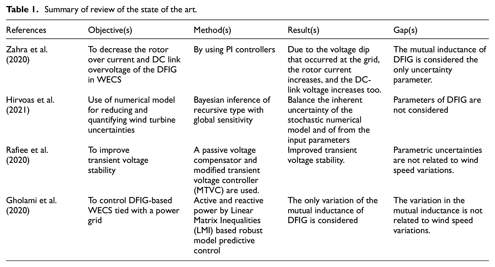
Focusing on the attainment of the optimal dynamic response of systems, advanced control methods such as adaptive controllers (Abubakr et al., 2022), linear-quadratic-gaussian regulators (Lai et al., 2022; Mojumder and Roy, 2021), fuzzy (Bhutto et al., 2020; Hosseinimoghadam et al., 2020; Modabbernia et al., 2022), Artificial Intelligence based controllers (Milkias et al., 2023; Nahas et al., 2021), and fractional order (Kalyan et al., 2022) has been proposed for the system. These papers show proper efficiency based on the simulation results. However, uncertainties of the machine parameters along with the controller have never been discussed. Even though the aforementioned works of literature cannot be the only ones to benchmark, many of them did not consider the parametric uncertainties on the performances of a grid-tied DFIG-based WECS. Taking these factors and their effects into account to bring further improvements in the performances of WECS, thus, the main objectives of this study are to:
Model grid coupled DFIG-based wind turbine system focusing on the uncertainties of parameters and investigating their pros and cons.
Formulate and examine the effects of parametric uncertainty on the dynamic performances of DFIG-based WECS.
In the subsequent sections of the paper, the DFIG-based WECS model, analysis of parametric uncertainty along with its effects on the performance of WECS, results, and discussion, conclusions and finally
Model formulation of the DFIG-based WECS
Formulation and implementation of a DFIG-based WECS model are used to investigate the effects of parametric uncertainties upon the dynamic performances of the overall system. Simplified stages of WECS flow are depicted in Figure 1. It shows the stages and energy conversion processes of the kinetic energy in the wind to electromechanical energy via an aerodynamic system and generator. Only a fraction of energy in wind is converted to electrical due to different losses as shown in Figure 1.
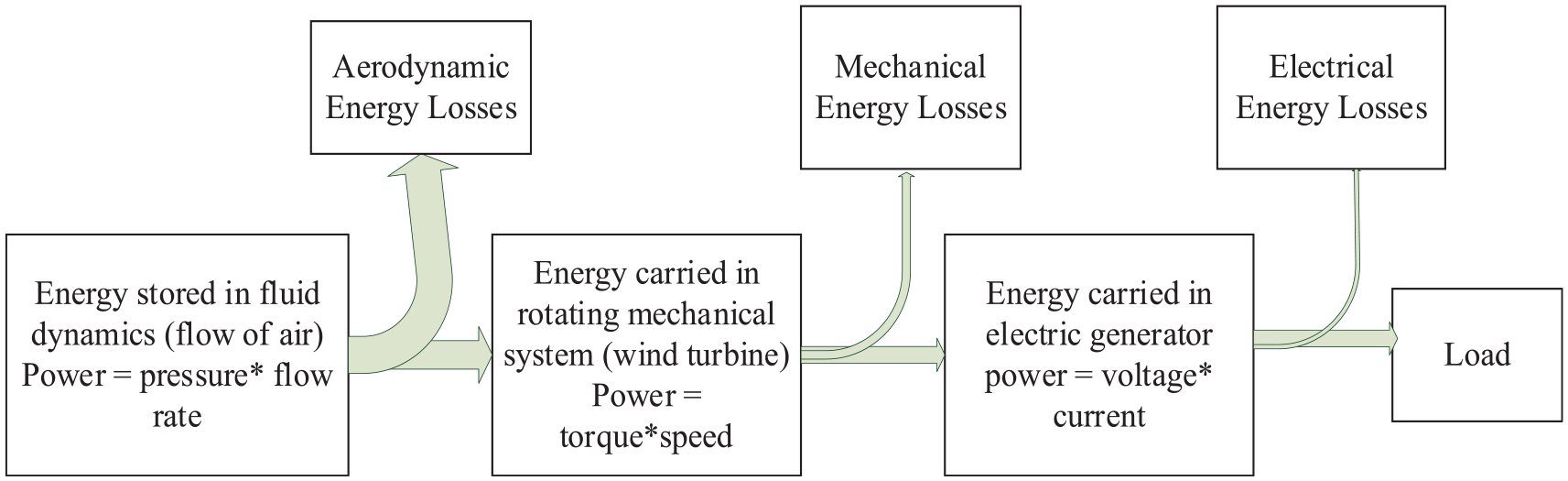
Wind energy conversion system (WECS) block diagram.
Neglecting all the losses, the mathematical model of complete WECS which can begin from an aerodynamic model is presented in the upcoming sections.
Aerodynamic model of wind turbine
This is formulated considering kinetic energy (E) of the moving mass (m) of fluid (air) with velocity (u = u(t)) which is expressed as:

Where the moving volume of the air is an area (A) times the distance moved in a second. That is volume/s

Only a portion of available power in the wind (Pw) can be converted to mechanical by wind turbines. Accordingly, the wind turbine rotor output power (Pt) and torque (Tt) are described as (Haile et al., 2021; Tuka and Endale, 2023):


Where R is the fixed length of the blade, ρ is air density (kg/m3),
Wind turbine drive train modeling
In the modeling of the wind turbine train, the main elements to be considered can be the rotor dynamics, low and high-speed shaft with gearbox, and the machine itself. The DFIG with drive train in the WECS is given by mathematical models in Haile et al. (2021). In this regard, a mathematical model under the consideration of a single mass model of the DFIG in a wind turbine system is given:


For unity gearbox ratio under the ideal assumption, the expressions of the transmitted torque, and angular velocities (n) of the rotor and generator are related as
Doubly fed induction generator modeling
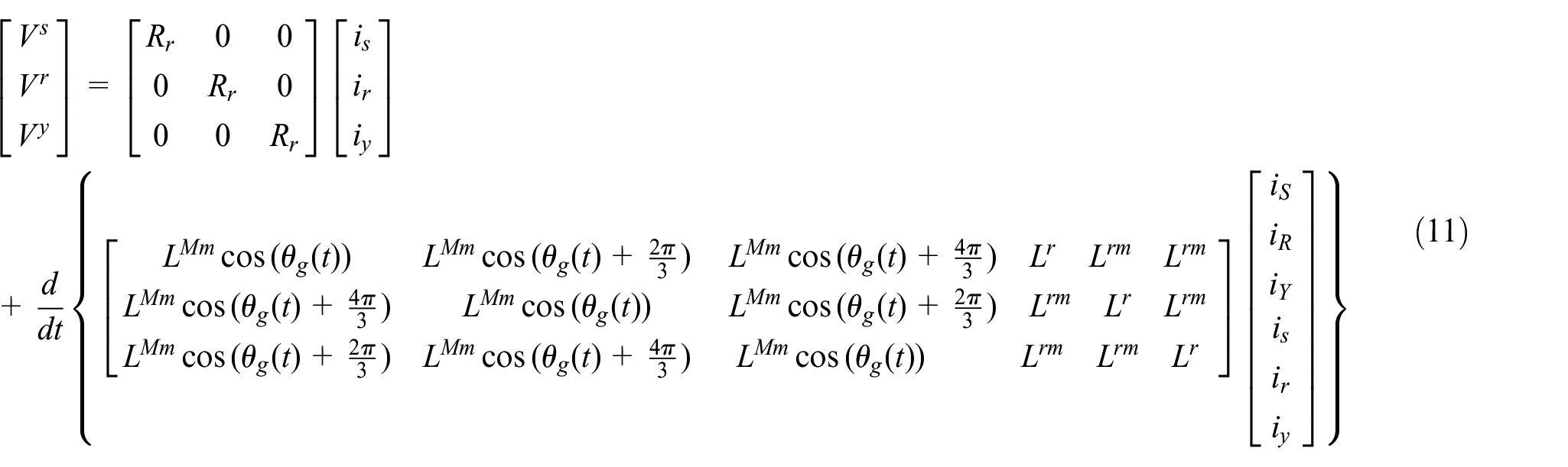
A rotating magnetic field in the air gap of the electric machine has a speed ω s = 2πfs concerning a stationary frame of reference where fs is the frequency of stator voltage, it can be seen that a rotating magnetic field in the air gap of an electric machine is given by a speed, ωs (https://fr.wind-turbine-models.com/turbines/2080-sany-se7715). Whereas the mechanical speed of the generator is given by, ω g = dθ g /dt, where θ g is the slip angle between the stator winding and the rotor frame. It forms slip speed, which induces a variable voltage in each of the stator conductors and its amount is related to the flux in the air gap. As presented in Faraday’s Law of Electromagnetic Induction (2021, online), the three-phase voltages of the stator windings S, R, and Y of DFIG are:
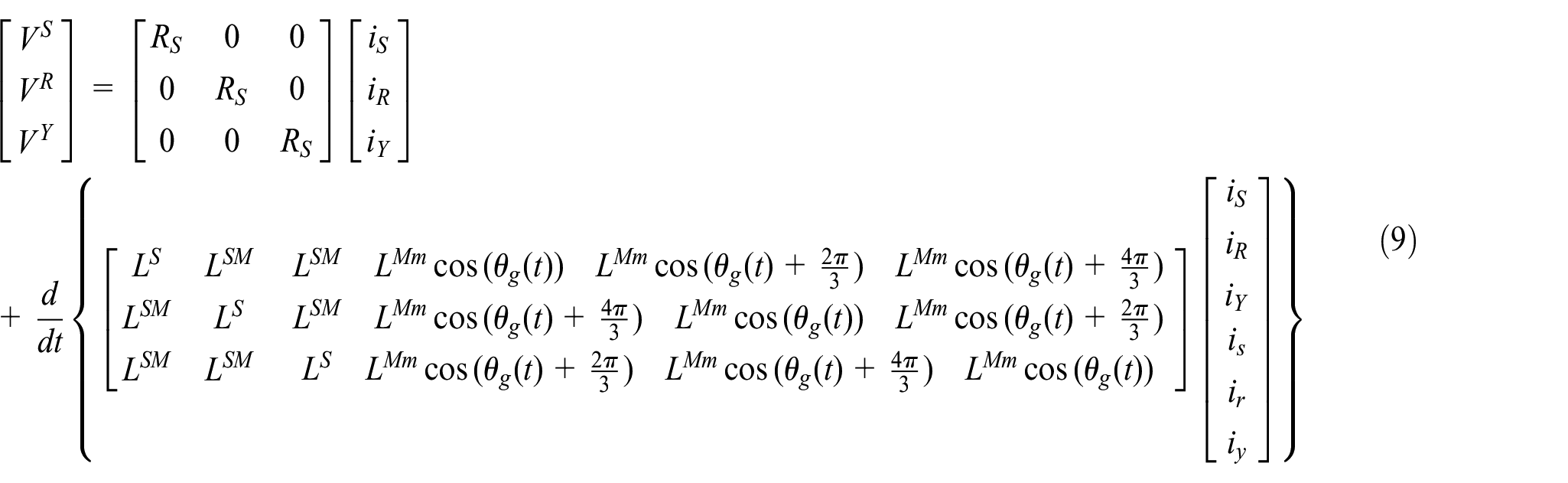
Assuming balanced and symmetrical windings of the stator and rotor, the resistances and fluxes at each phase are the same and constant. But, the mutual inductances between stator and rotor windings depend on
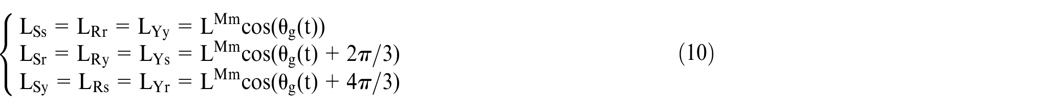
Where
As it is shown in Figure 2, the generator rotor’s electrical angular position

Where
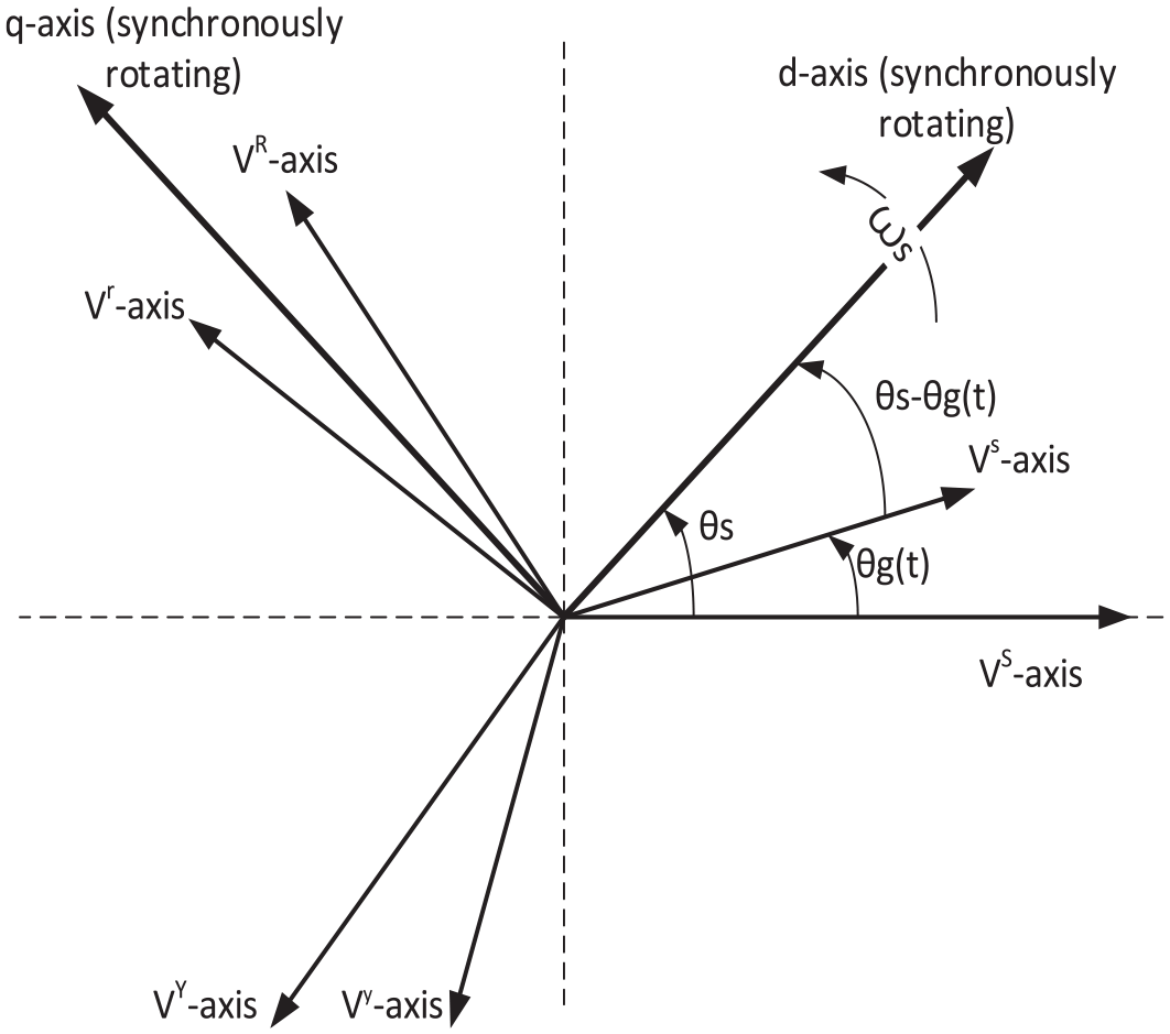
State-space representation of the DFIG under synchronous reference frame.
The generator rotor speed

This shows the effect of wind speed variation

For a fixed angular speed/frequency which is equal to grid frequency where

Where, Vsd, Vsq, Vrd, and Vrq are the d-q axis voltages of the stator and rotor, whereas isd, isq, ird, and irq are d-q axis currents of the stator and rotor. Assuming a symmetric arrangement of stator and rotor windings of DFIG and the zero components of dqo axis equal to zero, thus, the stator and rotor voltages in the dq axis are given as:
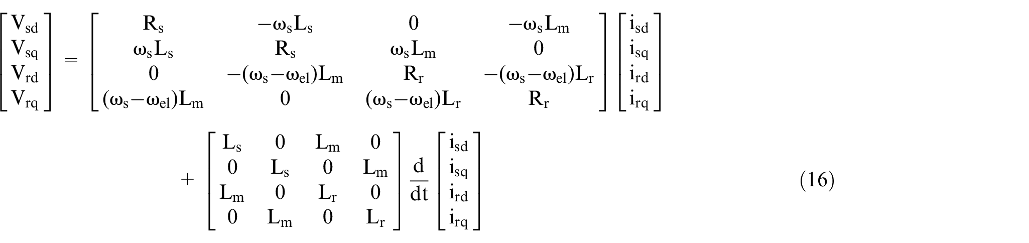
Where

As it can be seen from (16), the rotor winding and magnetization reactances in the system matrix are affected by rotor voltage slip frequency

The results obtained after the substitution of (18) into (16) can clearly show us the system model is varying with the wind speed which brings uncertainty in the stator and rotor winding voltages and currents. Therefore, the overall consequence will bring an effect on the dynamic performances of the DFIG-based WECS. For grid-tied wind turbines, this can further bring influence the power system’s dynamic performances, such as frequency stability, voltage stability, and rotor angle stability. Typically, the stability of the output power of DFIG is investigated under a synchronously rotating reference frame. The developed electromagnetic torque (Tem) in DFIG is formulated as:
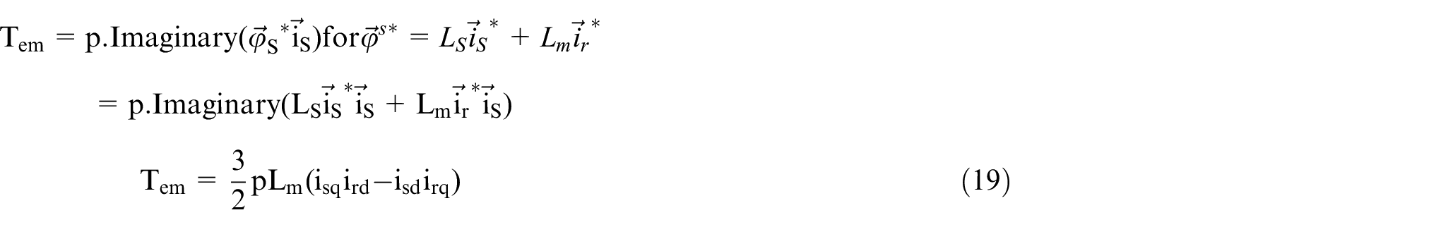
From (18) and (19), the DFIG output active electrical power (Pg) is expressed as:

From (20), we can see that a wind speed variation affects the generator power output and hence its frequency stability. The wind speed influences all the stator and rotor windings currents of DFIG by creating uncertainties in rotor reactance and mutual reactance. As is seen in Figure 3, the change in electrical speed is given as:

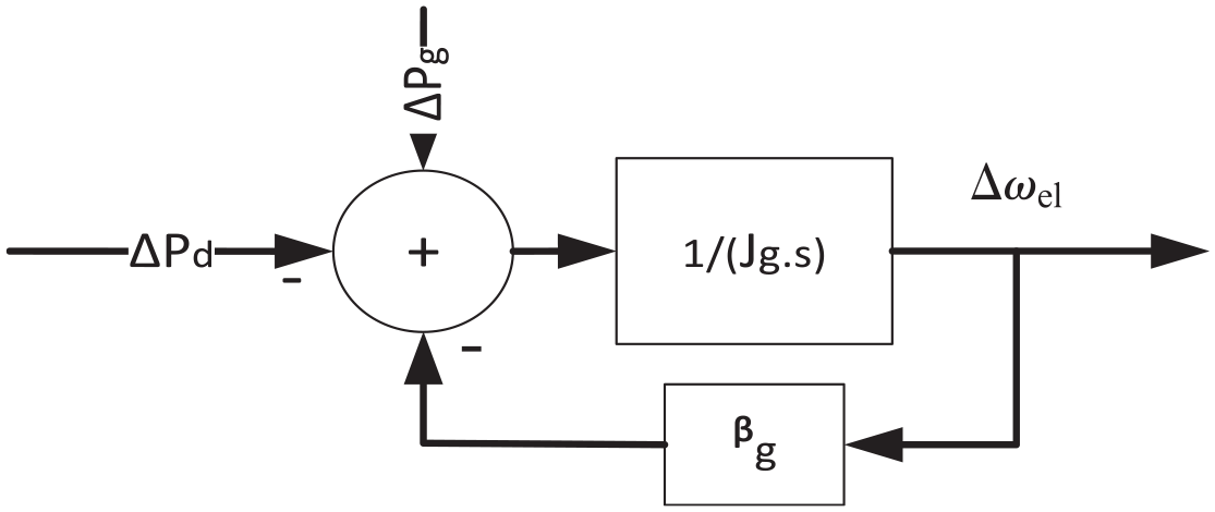
Representation of the variations of output power, demand, and rotor speed of DFIG.
By taking

Therefore, the variation in frequency (

Where fo is initial frequency.
The variation in frequency is due to variations in the power supplied by the generator (
A survey on frequency regulation techniques for mutable speed wind turbines is presented in Wu et al. (2018). Even though the parametric uncertainty in WECS is not included, the reasons for the stability failure of PMSG-based wind farm using the impedance model is analyzed under different control parameters, grid strength, and operational conditions (Yan et al., 2021a). The frequency stability of the DFIG-based wind turbine and photovoltaic power generation connected power system is studied (He et al., 2021). But variation in the wind speed is not considered. For grid-connected DFIG-based WECS, the steady-state voltage stability analysis is carried out by Adetokun and Muriithi (2021). However, the dynamic effect that can create transient stability on the power system is not covered. Considering (12), the rotor speed of the generator in electrical rad/s is given by:

Rotor acceleration in electrical rad/s is:

Substituting (18) into (24);

From (8), the DFIG rotor accelerating torque

From (18), (26), and (27), the DFIG rotor accelerating power, Pa is:

From (28), it can be concluded that the WECS linked to the power system will not disturb the transient stability of the power system if and only if Pa is zero by controlling the variation in wind speed. The actual value of Pa is the difference between the input mechanical power,

This shows the parametric uncertainties in DFIG disturb the transient stability of the power system. The detailed specifications of the machine are given in the Appendix of the paper.
Results and discussions
This study is carried out on a Sany SE7715 DFIG-based wind turbine installed at Adama II wind farm in Ethiopia by considering the variation of wind speed at 70 m hub height. The technical specification of the SE7715 wind turbine is presented in Appendix.
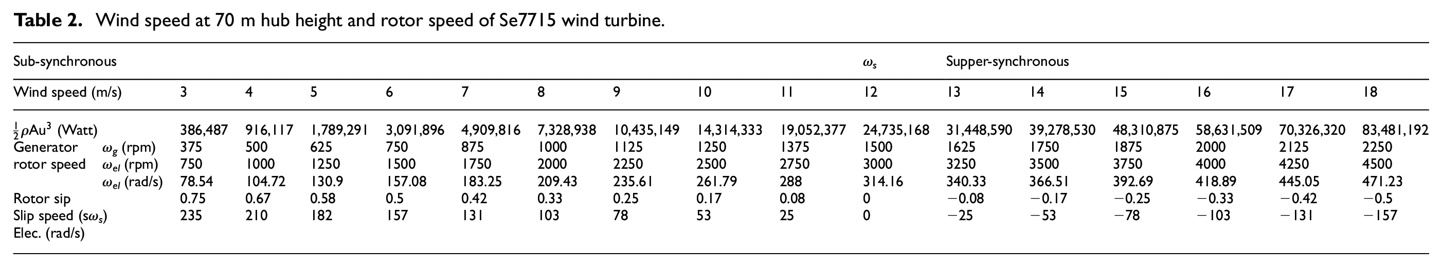
Using the formulated models with data in Appendix, the values of generator rotor speed and required variables are computed at different wind speeds and presented in Table 2. Most of the required basic data of DFIG-based WECS are computed and tabulated in Table 2 when operating at sub-synchronous (ω el ≤ ω s ), synchronous (at ω el = ω s no electromagnetic torque development so that no power generation), and super-synchronous (ω el ≥ ω s ) speeds. Inserting these data and the system specifications (Appendix) into (16), the variations in the model of DFIG-based WECS are computed with coefficient matrices listed in Table 3. From above Table 2, the variation of wind speed causes the generator rotor speed (ω el ) to deviate between 0.25ω s ≤ ω el ≤ 1.4ω s . Consequently, using (28), the rotor winding reactance of DFIG changes from its nominal value, Xr = 1.31 mΩ to 0.983 ≥ Xr ≥ −0.655 mΩ; and the mutual reactance between stator and rotor windings of the DFIG changes from its nominal value, Xm = 0.941 Ω to 0.758 ≥ Xm ≥ −0.4708 Ω. Due to these uncertainties, the dynamic model of the system matric (A) of DFIG-based WECS given in (30) is varying, whereas the input matrix (B) is independent of the uncertain parameters and remains constant.
Wind speed at 70 m hub height and rotor speed of Se7715 wind turbine.
System matrix of dynamic model of DFIG-based WECS and its stability condition.
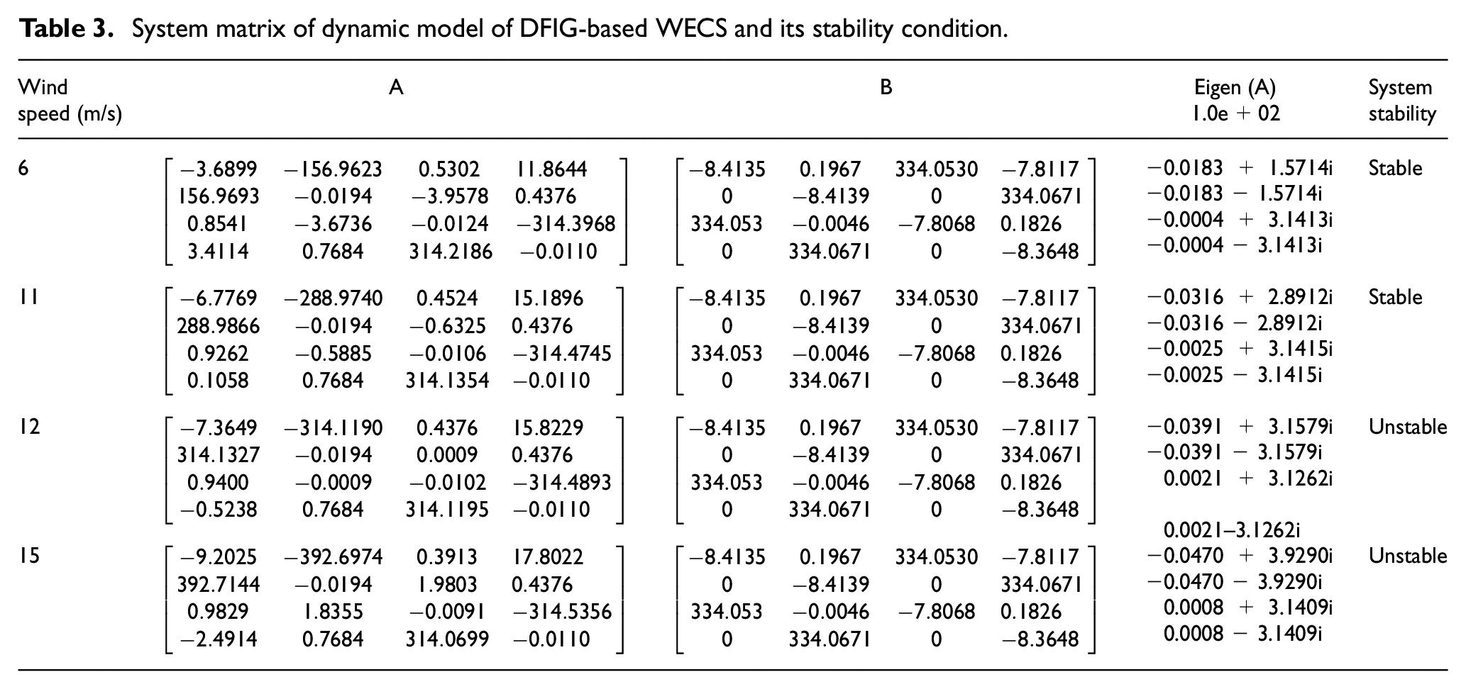

Table 3 indicates a dynamic system matrix model of DFIG-based WECS and its stability conditions.
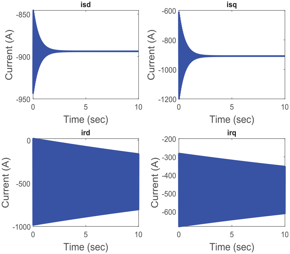
As it is indicated in Table 3, the dynamic model of DFIG-based WECS is stable for varying wind speeds when it is less than the rated value (12 m/s) and becomes unstable for wind speeds that are equal to and/or greater than the rated value. This is because the WECS parameters are mainly varying with the given wind speed. Therefore, the parametric uncertainties in the WECS are mainly affecting the stability and the overall performance of the power plant. The stator and rotor currents of the DFIG in d-q axes are solved at the wind speed of 6, 12, 14, and 15 m/s by using (30) and Table 3. Accordingly, the results are indicated in Figures 4–7. At a wind speed of 6 m/s, the corresponding rotor speed is 157 electrical rad/s, indicating that the generator is operating in the sub-synchronous mode of operation. At this speed, Figure 4 shows that a stable current response with the rotor winding current in d-q axes has got high frequency for the machine connected to a partial load. When the wind speed is changed to 12 m/s, the generator runs at synchronous speed. This operation is described in Figure 5 indicating that the rotor current response is unstable with periodically increasing amplitude.
Stator and rotor currents in d-q axes at a wind speed of 6 m/s for partial load.
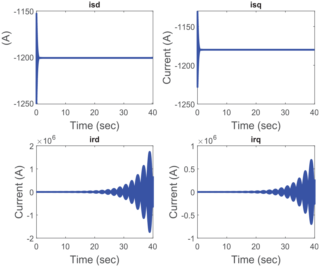
Stator and rotor currents in d-q axes at a wind speed of 12 m/s for a full load.
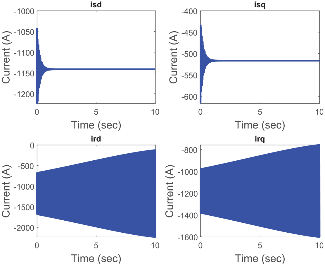
d-q axes currents of the stator and rotor at a wind speed of 14 m/s for a full load.
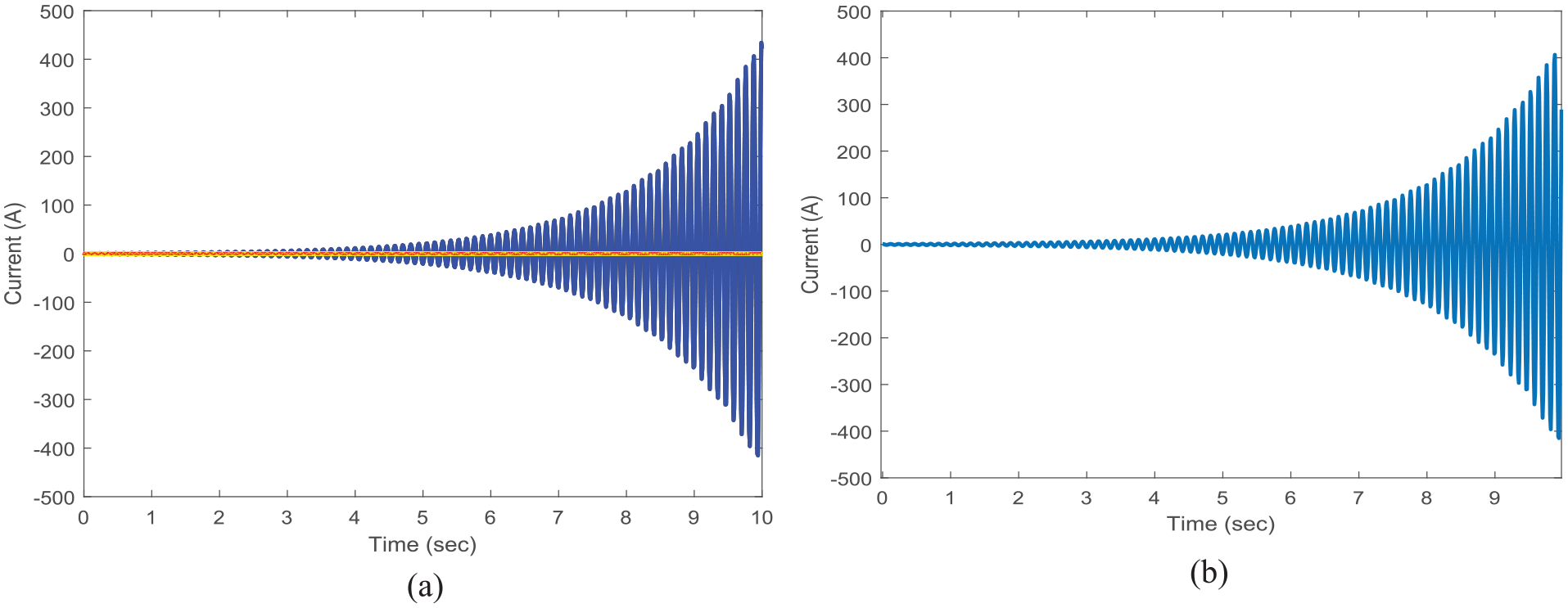
Stator current (a) ird and (b) irq at wind speed 15 m/s and for a partial load.
As the wind speed changes from 12 to 14 m/s, the generator rotates at an equivalent speed of 366.8 electrical rad/s. Hence the generator is running in the supper-synchronous mode of operation.
In the super synchronous mode of the generator operation, both windings of the stator and rotor of the DFIG deliver power to the grid. This is depicted in Figure 6 from which it can be deduced that the rotor current response is unstable at high frequencies. On the other hand, the stator winding currents in the d-q axes are completely stable. Thus, the machine can be connected to a full load scale.
Figure 7 shows the unstable response of the rotor dq currents when the wind turbine is driven by wind speed beyond 15 m/s under partial load consideration. These results indicate that the rotor current is highly unstable. The main causes of this instability in WECS are the changes in its parameters during wind speed variations.
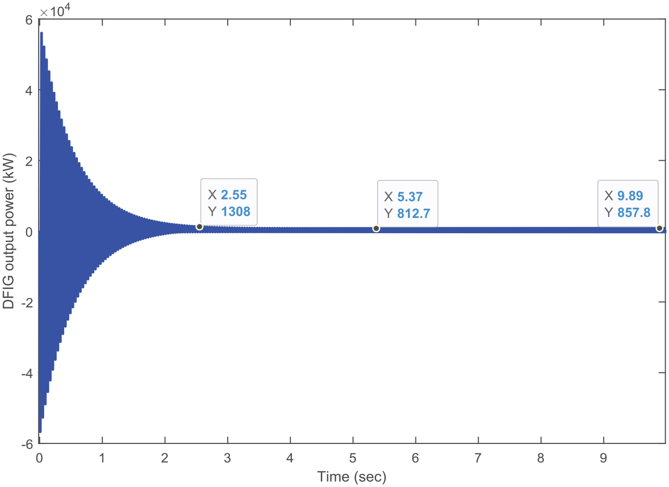
The power output of DFIG-based WECS is plotted in Figures 8–10 at wind speeds of 6, 12, and 14 m/s respectively. When the wind speed is below 12 m/s, the variation in rotor winding and mutual reactances are small. Thus, their effect on the generator output power is less. That means the output power is stable as indicated in Figure 8. When the speed of wind goes beyond the rated value, the effects of uncertainties are increased and hence perturbations are observed at the rotor current. As a result, the output power becomes unstable. Comparing Figures 9 and 10 with Figures 5 and 6, the effect of the rotor current over the stator current is seen to be more dominant upon the output power variations. The output power oscillates with a higher magnitude as shown in Figure 10. The same pattern is seen in the rotor current as shown in Figure 5.
The output power of DFIG at a wind speed of 6 m/s.
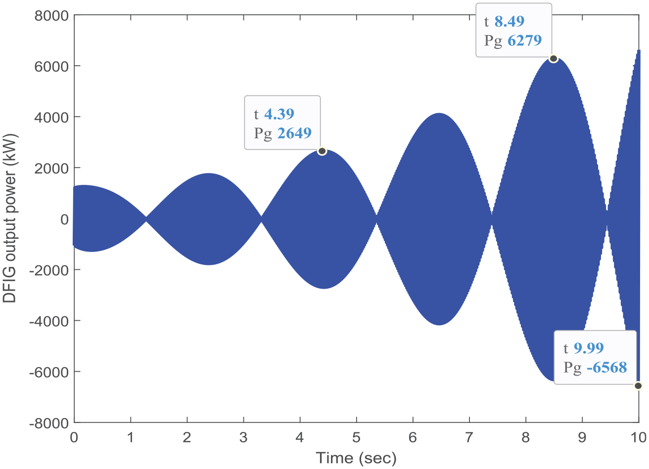
The output power of DFIG at a wind speed of 12 m/s.
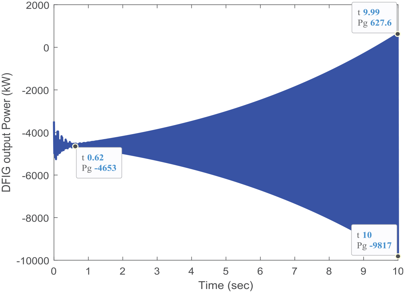
The output power of DFIG at a wind speed of 14 m/s.
The impact of the parametric uncertainties on the transient stability of DFIG-based WECS is depicted in Figures 11 and 12 for wind speeds of 6 and 14 m/s respectively. At 6 m/s of wind speed, Figure 11 shows that the accelerating power is decreasing toward zero. It indicates the plant is transiently stable.
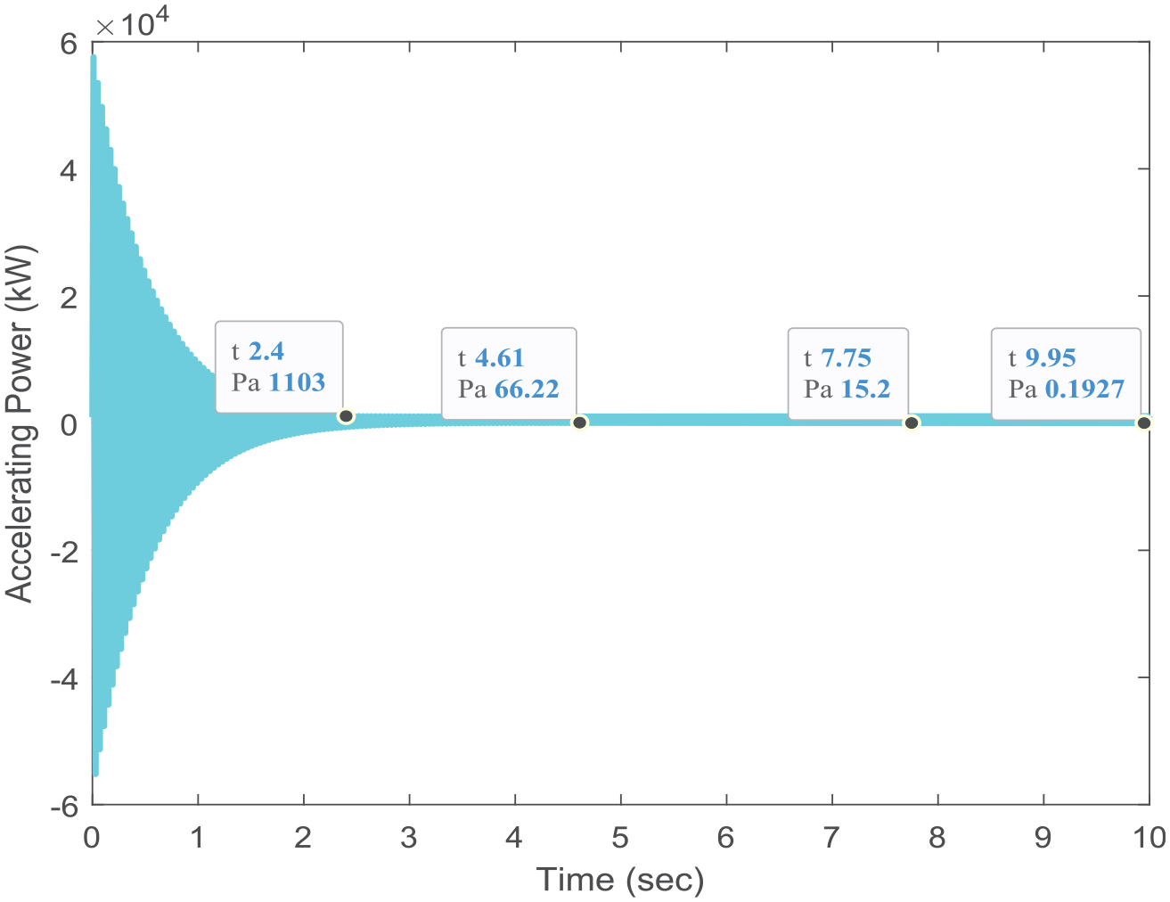
Accelerating power at 6 m/s wind speed.
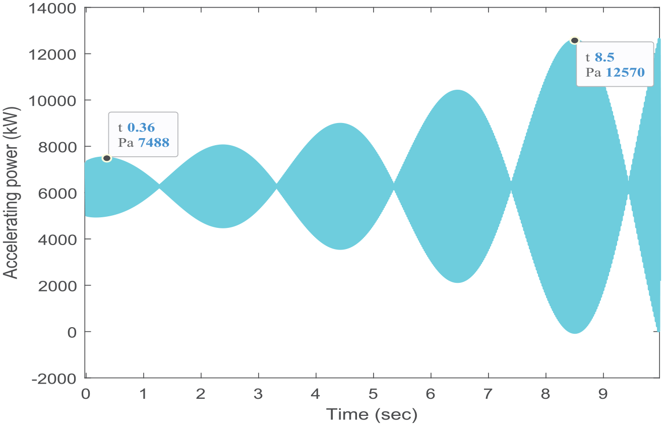
Accelerating power at 12 m/s of wind speed.
Figure 12 shows the oscillating nature of accelerating power with increased amplitude at 12 m/s wind speed. This disturbs the transient stability of the system.
In summary, it can be seen that the winding reactance of the rotor and mutual magnetization reactance are the uncertain parameters in the dynamic model of DFIG-based WECS. These reactances change with wind speed variations and make the system unstable when the wind speed is equal to or greater than the rated wind speed affecting the dynamic performance of the system.
Conclusion
This study focused on the Doubly Fed Induction Generator-based
For a grid-connected wind turbine system with DFIG-based WECS, the significance of uncertainties of parameters will not be limited to the unit itself. However, it disturbs the stability of the entire networked system and causes failure in the power network
Contributions
The main contribution of this work is:
It enhances power extraction capability under uncertain wind conditions.
It contributes to a better understanding of the parameter uncertainty under the dynamic condition of the wind energy conversion system for a better energy-capturing mechanism.
Variable speed wind turbine operation, generator, converters, and their modeling as well as control concepts during uncertain parameter considerations
The paper well identified the most main uncertain parameters that occurred due to the variation of the angular positions of the rotor which is further caused by varying wind speeds.
Future scope of work
Footnotes
Appendix
DFIG specifications (Ayenew and Berhanu, 2022; Bin et al., 2011).
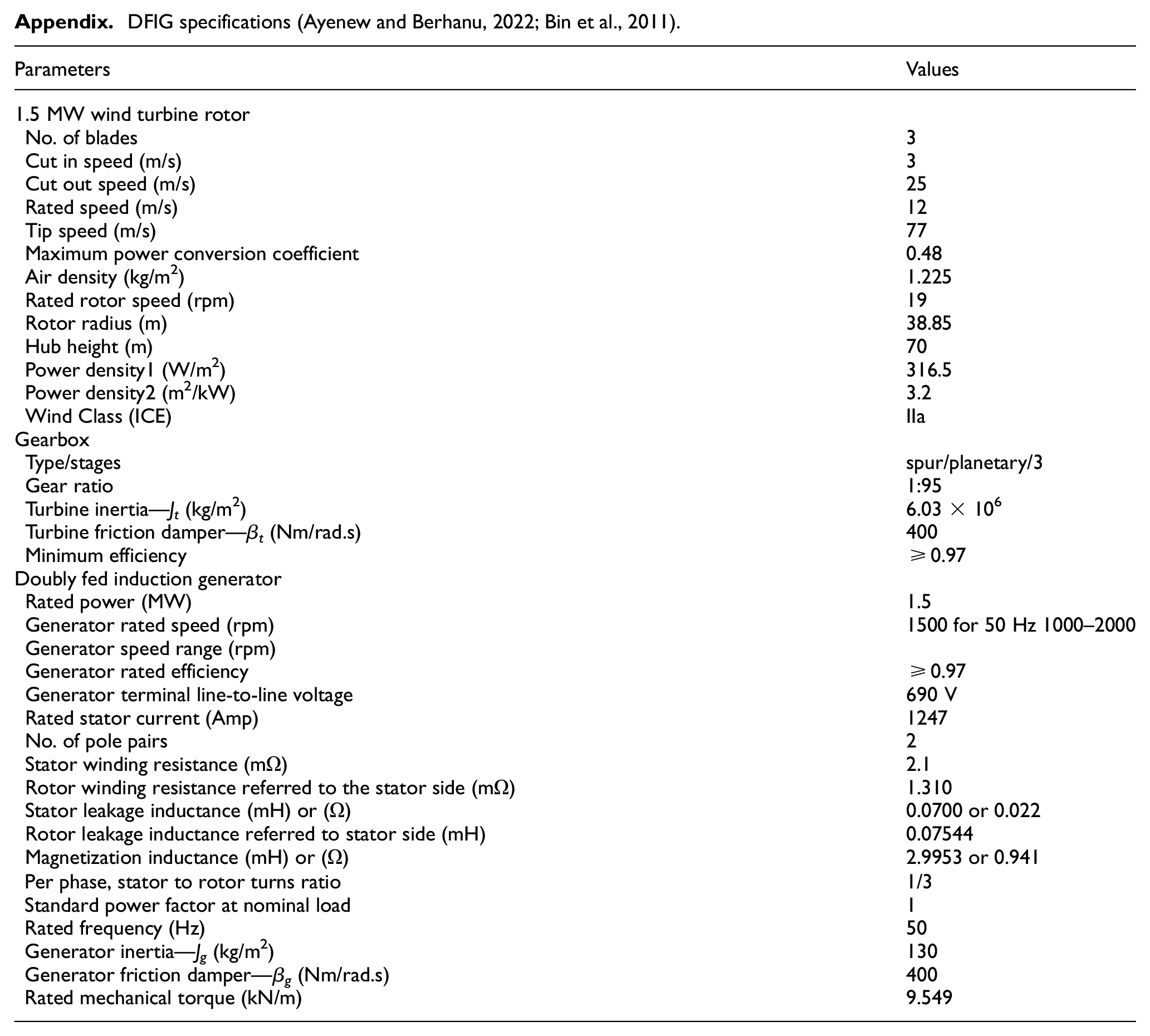
| Parameters | Values |
|---|---|
| 1.5 MW wind turbine rotor | |
| No. of blades | 3 |
| Cut in speed (m/s) | 3 |
| Cut out speed (m/s) | 25 |
| Rated speed (m/s) | 12 |
| Tip speed (m/s) | 77 |
| Maximum power conversion coefficient | 0.48 |
| Air density (kg/m2) | 1.225 |
| Rated rotor speed (rpm) | 19 |
| Rotor radius (m) | 38.85 |
| Hub height (m) | 70 |
| Power density1 (W/m2) | 316.5 |
| Power density2 (m2/kW) | 3.2 |
| Wind Class (ICE) | IIa |
| Gearbox | |
| Type/stages | spur/planetary/3 |
| Gear ratio | 1:95 |
| Turbine inertia—Jt (kg/m2) | 6.03 × 10⁶ |
| Turbine friction damper—β t (Nm/rad.s) | 400 |
| Minimum efficiency | ≥0.97 |
| Doubly fed induction generator | |
| Rated power (MW) | 1.5 |
| Generator rated speed (rpm) | 1500 for 50 Hz 1000–2000 |
| Generator speed range (rpm) | |
| Generator rated efficiency | ≥0.97 |
| Generator terminal line-to-line voltage | 690 V |
| Rated stator current (Amp) | 1247 |
| No. of pole pairs | 2 |
| Stator winding resistance (mΩ) | 2.1 |
| Rotor winding resistance referred to the stator side (mΩ) | 1.310 |
| Stator leakage inductance (mH) or (Ω) | 0.0700 or 0.022 |
| Rotor leakage inductance referred to stator side (mH) | 0.07544 |
| Magnetization inductance (mH) or (Ω) | 2.9953 or 0.941 |
| Per phase, stator to rotor turns ratio | 1/3 |
| Standard power factor at nominal load | 1 |
| Rated frequency (Hz) | 50 |
| Generator inertia—Jg (kg/m2) | 130 |
| Generator friction damper—β g (Nm/rad.s) | 400 |
| Rated mechanical torque (kN/m) | 9.549 |
Declaration of conflicting interests
The author(s) declared no potential conflicts of interest with respect to the research, authorship, and/or publication of this article.
Funding
The author(s) received no financial support for the research, authorship, and/or publication of this article.