
Abstract
In this article, a methodology is presented for the design of a hydraulic-pneumatic flywheel integrated in a wind turbine rotor. The flywheel enables wind turbines to contribute to power system inertia and it can be used for mitigating loads on the wind turbine. The methodology is applied to the geometry of an existing blade design of a 5-MW wind turbine, but is valid for any arbitrary rotor blade. Several flywheel configurations are derived causing an increase in rotor inertia of the 5-MW wind turbine by 15%, but differ in the position, dimensions and masses of the hydraulic components. These parameters determine the total mass of the hydraulic-pneumatic flywheel, and hence the impact on the mechanical loads on the wind turbine. As a result, a weight-optimized configuration for a flywheel integrated in a wind turbine rotor is derived.
Introduction
Conventional power plants are increasingly being substituted by renewable energy sources such as wind turbines (WTs) and photovoltaics. This transition brings with it a reduction in power system inertia as this is essentially contained in synchronous generators of conventional power plants. As these generators are directly connected to the grid, their rotational speed changes when there is a deviation in grid frequency (Díaz-Conzález et al., 2014). As a consequence, kinetic energy is transformed to electric energy. This is exchanged with the grid in order to limit the speed with which the frequency deviates. Hence, it provides primary control plants with more time to activate their power reserves (Yingcheng and Nengling, 2011). The smaller the power system inertia, the faster the grid frequency deviates, and thus, the less time for primary control power plants to respond to a power imbalance (Keung et al., 2009).
State-of-the-art WTs are not directly connected to the grid but via frequency converters, and thus they do not inherently contribute to power system inertia (Duckwitz et al., 2014). A further replacement of conventional power plants by these WTs could potentially endanger power system stability and result in blackouts.
Enabling WTs to contribute to power system inertia has been widely discussed and is called ‘synthetic inertia’ (Díaz-Conzález et al., 2014; Duckwitz et al., 2014; Erlich and Wilch, 2010; Keung et al., 2009; Yingcheng and Nengling, 2011). In the event of a drop in grid frequency, kinetic energy of a WT rotor is released by decreasing its rotational speed. As a result, the WT’s power output is temporarily increased (Fischer et al., 2014). A few seconds after this increased power feed-in, the power of the WT has to be decreased for a while in order to regain optimal rotational speed. However, the power output is decreased at a moment in time when the grid still needs additional power (Asmine and Langlois, 2014). This time span of reduced power is called ‘recovery phase’ (Juankorena et al., 2009).
Rapid controllable power can be provided to the power system by energy storage systems such as battery banks and conventional flywheels (FWs). However, additional frequency converters are needed in order to connect them to the grid connection point of a wind farm. Furthermore, conventional FWs show high self-discharge rates (Hadjipaschalis et al., 2009). Also, such systems do not provide additional advantages for the WT.
The proposed FW system in a WT rotor uses the grid connection infrastructure of the WT and its storage time is unlimited, that is, self-discharge is avoided (Jauch, 2014). Furthermore, the recovery phase can be circumvented because kinetic energy is stored or released by changing the rotor’s mass moment of inertia, JRot, independent of the rotational speed (Jauch and Hippel, 2015).
Changing the rotors mass moment of inertia causes a variable eigenfrequency of the rotor blades, which can be used to avoid mechanical vibrations (Jauch, 2016). Depending on the rotational speed of the rotor, a WT is excited to mechanical vibrations with different frequencies. An equality between excitation frequency and eigenfrequency of a WT component leads to resonances which increase the stress on the WT. The FW system can be used in order to avoid these resonances by specifically controlling the eigenfrequency of the rotor blade depending on the rotational speed. As a result, loads on the WT can be mitigated.
The general idea of such an energy storage system was introduced in previous work of the authors (Jauch, 2014). The FW was further developed to a hydraulic-pneumatic system consisting of two piston accumulators in each blade connected by a hydraulic tube (see Figure 1). In the following sections, all variables referring to the blade root accumulator or blade tip accumulator are named with the index j = 1 or j = 2, respectively (for a list of all variable names with descriptions, see Appendix 1). The rotor’s mass moment of inertia is changed by moving a fluid mass, mfluid, from the blade root accumulator to the blade tip accumulator or vice versa. The equations describing the hydraulic-pneumatic FW and its performance were previously presented (Jauch and Hippel, 2015).
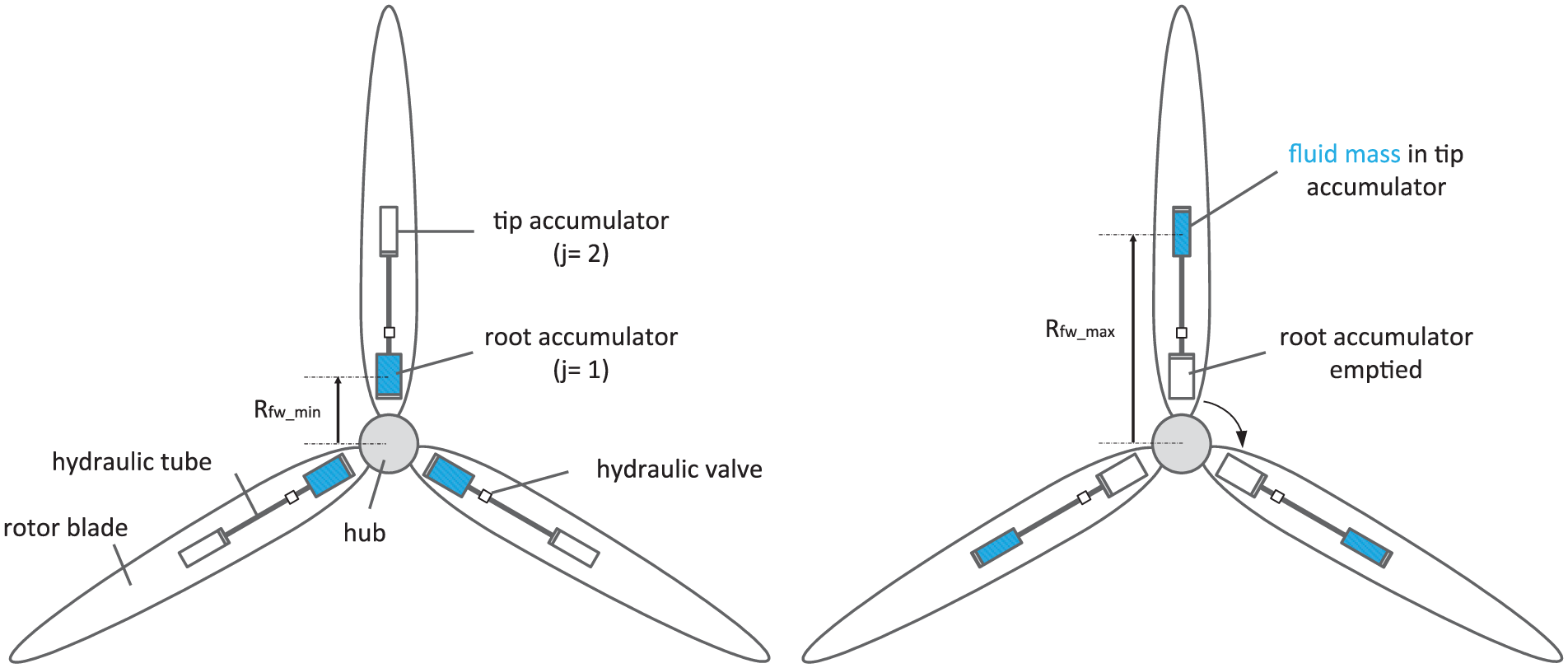
Left: Simplified sketch of the FW system in the discharged state. Right: FW in the charged state.
The FW is discharged, when the fluid mass is in the blade root accumulators as can be seen in Figure 1 (left). It becomes charged when the fluid flows into the tip accumulators, either as a result of centrifugal forces, or by a pump (see Figure 1, right). Moving a fluid mass in each blade from the smallest radius, Rfw_min, to the largest radius, Rfw_max, results in an FW inertia, Jfw, as described by equation (1)

The hydraulic system was designed for a generic 2 MW WT in cooperation with HYDAC TECHNOLOGY GmbH (HYDAC) based on previously defined parameters (Jauch, 2014; Lauer, 2015). As a result, the rotor inertia, JRot_2MW, of the considered generic 2 MW WT was increased by approximately 15% (Jauch, 2014). Varying the rotor inertia by 15% shows a superior performance compared to ‘synthetic inertia’, and hence 15% inertia increase is taken as a reference value for further research (Jauch and Hippel, 2015).
The FW system has an influence on blade dynamic properties and mechanical loads and hence on the structural design of a rotor blade. In order to study the feasibility of the FW system, an existing blade design is used and different configurations of the hydraulic system that are permissible for the given geometry are derived. Hence, the results could be used for the integration of the FW system in an existing blade with certain modifications depending on the particular blade design.
The 5-MW WT of the National Renewable Energy Laboratory (NREL) is frequently used by wind energy research institutes and its data are publicly available (Jonkman et al., 2009). Consequently, the FW system was modified and adapted to this WT. The desired increase in rotor inertia of the 5-MW WT, JRot_5MW, could be achieved by applying ‘parallel packaging’, which requires installing piston accumulators side by side at the same rotor radius, R (Hippel and Jauch, 2015). However, the stationary masses of the piston accumulators and thus the total mass of the hydraulic system per blade were not considered in the previous study.
In order to analyse the inevitable impact of the FW system on the mechanical loads of the WT, not only the fluid mass but also the stationary masses of the hydraulic components need to be considered. The share of stationary masses on the total mass of the FW system is significant as most of the conventional hydraulic components are made of steel. The mass of the root and tip accumulator corresponds to more than 57% of the total mass of the previously designed FW system for the generic 2 MW WT (Lauer, 2015). Therefore, the derivation of stationary masses for different FW configurations, which cause an increase in rotor inertia of the 5-MW WT by 15%, is the key point of the article at hand. An FW configuration is characterized by four design criteria:
The number of tip accumulators;
The position, where the tip accumulator(s) is/are installed, that is, the rotor radius;
The length of the tip accumulator(s), lAcc_2;
The total mass of the hydraulic system per blade, mtotal (including the fluid mass and the stationary masses of the piston accumulators in the blade root and blade tip, mst_1 and mst_2, respectively).
At first, the required dimensions of the hydraulic system as shown in Figure 1 and the resulting total mass are analysed for different positions along an infinitely stiff blade. Subsequently, the potential deflection of the blade is considered in the selection of possible FW configurations. Applying parallel and serial packaging increases the number of tip accumulators, and thus the total mass of the hydraulic system per blade also increases. However, these techniques enhance the possible increase in rotor inertia of the 5-MW WT. As a result, several FW configurations are derived differing in the four design criteria but all causing an increase in rotor inertia of the 5-MW WT by 15%.
Derivation of installation space for piston accumulators inside the blades
As mentioned above, the FW system is modified for the NREL 5-MW WT as its data are publicly available. A detailed reference model of the 5-MW NREL blade was developed by Brian R. Resor, and hence this model is used in order to derive the exact internal dimensions of the blade (Resor, 2013). The methodology introduced in the following sections is applied to Resor’s blade model but it is valid for any arbitrary rotor blade.
In order to maximize the resulting FW inertia, the smallest radius of the FW needs to be minimized and the largest radius has to be maximized (see equation (1)). This can be achieved by installing the tip accumulator very close to the blade tip. In this region of the blade, the possible installation space for a piston accumulator is maximal between the shear webs (SWs), and hence the tip accumulator is installed between them (see plot on the bottom of Figure 2).
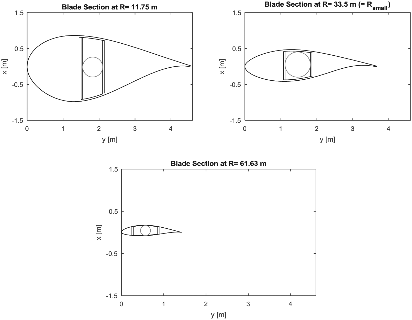
Top (Left): Piston accumulator between SWs at 11.75 m rotor radius. Top (Right): Piston accumulator between SWs at 33.5 m rotor radius. Bottom: Piston accumulator between SWs at 61.63 m rotor radius.
For the sake of simplicity, the piston accumulators in the blade root should also be installed between the SWs. In order to minimize the smallest radius of the FW, the outer diameter of the blade root accumulator, Do_1, should be as large as possible. In the blade root region, the distance of pressure side to suction side is much greater than the distance between the SWs (see plot on the top of Figure 2, left). Consequently, the maximal outer diameter of the blade root accumulator is determined by the distance between the SWs.
The maximum permissible length of a conventional piston accumulator, lAcc_max, equals 12 m. When the blade tip accumulator is thicker than the blade root accumulator, the maximal length of a piston accumulator in the blade root may be exceeded for a certain fluid mass. Consequently, the distance between the SWs should be measured or computed from the blade root up to a blade length of 12 m.
The total length of the root accumulator, lAcc_1, changes depending on the contained fluid mass. In order to ensure that piston accumulators of different lengths fit between the SWs, the minimal measured or computed distance between the SWs determines the outer diameter of the blade root accumulator. The outer diameter of a blade root accumulator within the Resor blade is derived as Do_1 = 548 mm and is set constant for all possible FW configurations.
The internal distance of pressure side to suction side and the distance between the SWs should be measured or computed along the whole blade length. Towards the blade tip, the distance between pressure side and suction side decreases strongly, whereas the SWs remain rather parallel (see Figure 2). The distance between pressure side and suction side becomes smaller than the distance of the SWs at a certain radius, Rsmall. This occurs at a rotor radius of 33.5 m for Resor’s blade model (see plot on the top of Figure 2, right). Starting at this blade length up to the blade tip, the outer diameter of the blade tip accumulator, Do_2, is determined by the internal distance of pressure side to suction side.
Starting at the blade section of 33.5 m rotor radius, Resor’s blade model is described by 14 blade sections and the derived possible outer diameters of the blade tip accumulator are shown as circles in Figure 3. The outer diameters of the blade tip accumulator at the last 14 blade sections are used in order to derive an interpolation function as depicted in Figure 3. As a result, the outer diameter of the tip accumulator can be computed as a function of the rotor radius for any radius between Rsmall and tip radius, Rtip. Consequently, the stationary masses of hydraulic components such as covers and pistons can be derived as discussed in the following section.
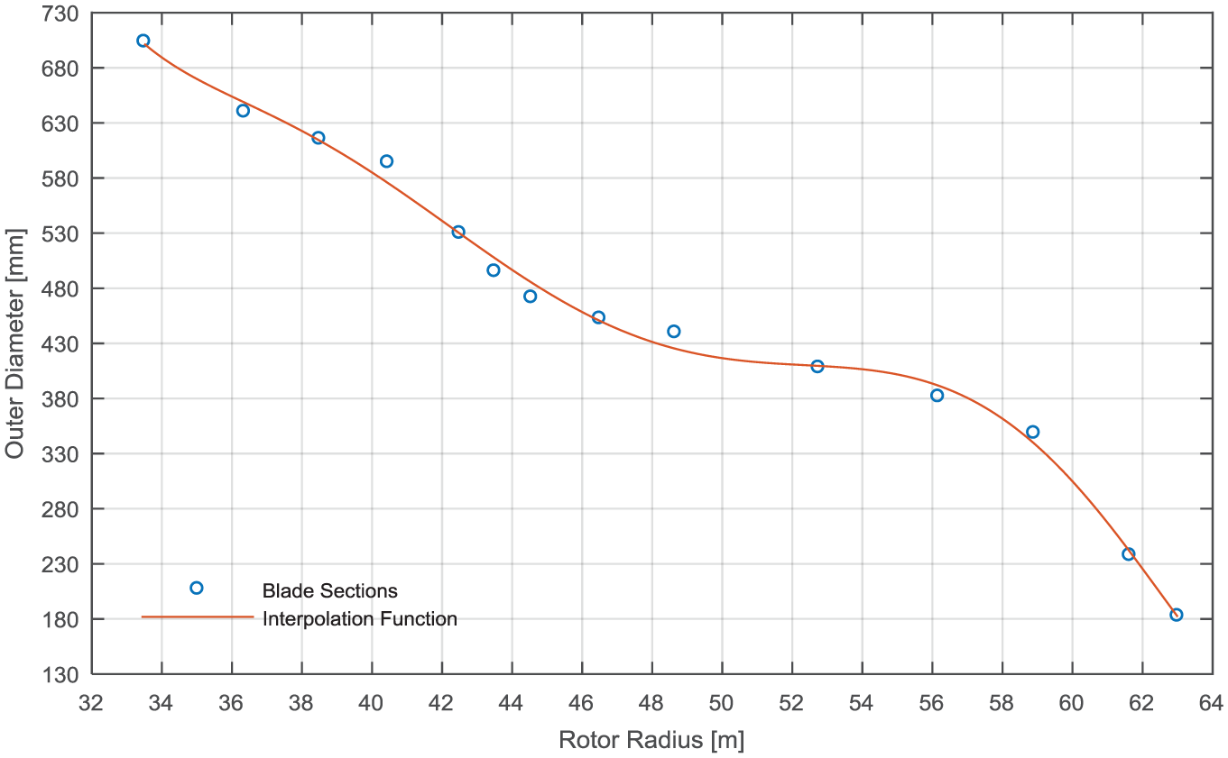
Computed outer diameter of blade tip accumulator at the last 14 blade sections of the Resor blade and derived interpolation function.
Derivation of stationary masses
The computation of stationary masses is focused on the piston accumulators. The masses of the hydraulic tubes, the valves and gas bottles are neglected in this analysis because they are much lighter than the piston accumulators. A piston accumulator consists of a cylindrical steel shell, a cover on the fluid side, a cover on the gas side and a piston. The covers of conventional piston accumulators are made of steel, whereas the piston is made of aluminium. The derived equations for computing the stationary masses can obviously be applied to hydraulic components made of other materials, that is, other densities.
The position of the tip accumulator, that is, rotor radius, determines its outer diameter, and thus the mass of its cover on the fluid side, mcf_2, the mass of its cover on the gas side, mcg_2, and the mass of its piston, mp_2. The stationary masses of these components of the root accumulator are constant, as its outer diameter is equal for all configurations. The masses of the steel shells, ms_1 and ms_2, depend on the outer diameter, the wall thickness, t, and the total length of the piston accumulators. As a result, the stationary masses of each accumulator can be computed by equation (2)

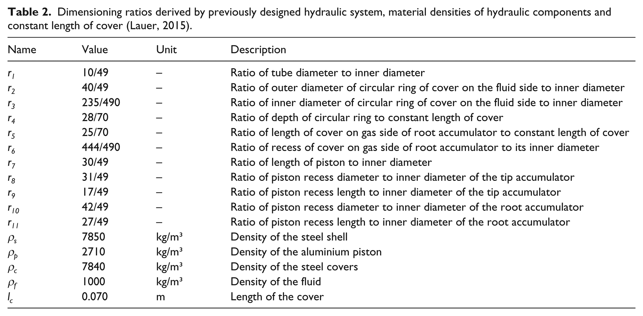
The derivation of the stationary masses for the individual hydraulic components such as covers and pistons is based on the previous design by HYDAC (Lauer, 2015). The previous design includes, among others, technical drawings of the hydraulic components of two piston accumulators. The technical drawings are used in order to derive dimensioning ratios, r1–r11 (see Appendix 2), with which the dimensions of hydraulic components of different diameters can be computed. The derivation of the dimensioning ratios and thus the stationary masses of the individual components are explained in the following sections.
Cylindrical shell
The main driver in terms of dimensioning the hydraulic components is the inner diameter of the piston accumulators, Di_1 and Di_2. They are derived by the calculated outer diameters and the prevailing hydraulic pressure, p. The hydraulic pressure depends on the density of the fluid, ρf, the rotational speed of the WT rotor, ωrot, and the rotor radius and is computed as documented in Jauch and Hippel (2015). As a result, the required wall thickness, treq, for a cylinder under pressure can be calculated by equation (3) (Lauer, 2015)
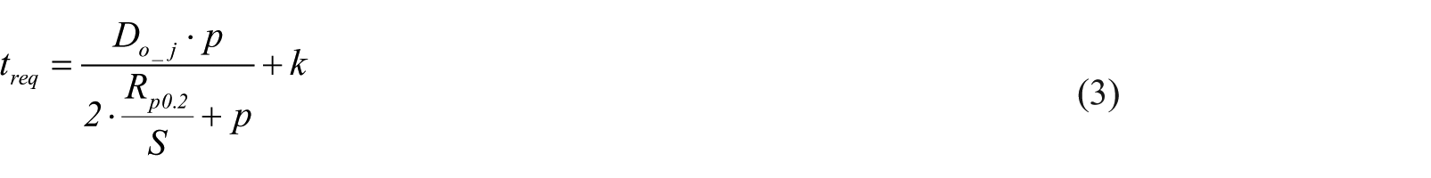
Conventional piston accumulators are made of steel with a yield strength, Rp0.2 = 755 N/mm2. A safety factor of S = 1.5 and a tolerance of k = 1 mm are applied for all calculations (Lauer, 2015). The wall thickness is derived by rounding the required wall thickness up to the nearest whole number, and thus the inner diameter can be computed. As a result, the mass of the steel shells (with density ρs) of the root accumulator and tip accumulator can be derived by equation (4) for different total lengths and diameter

The total lengths of the piston accumulators depend on the dimensions of the covers and pistons and the contained fluid mass and will be discussed in section ‘FW configurations’.
Covers
All covers are made of steel with density ρc (see Appendix 2). The dimensions of the cover on the fluid side of the root and tip accumulator are equal and depicted in Figure 4(a). Consequently, their masses, mcf_1 and mcf_2, can be expressed by equation (5)

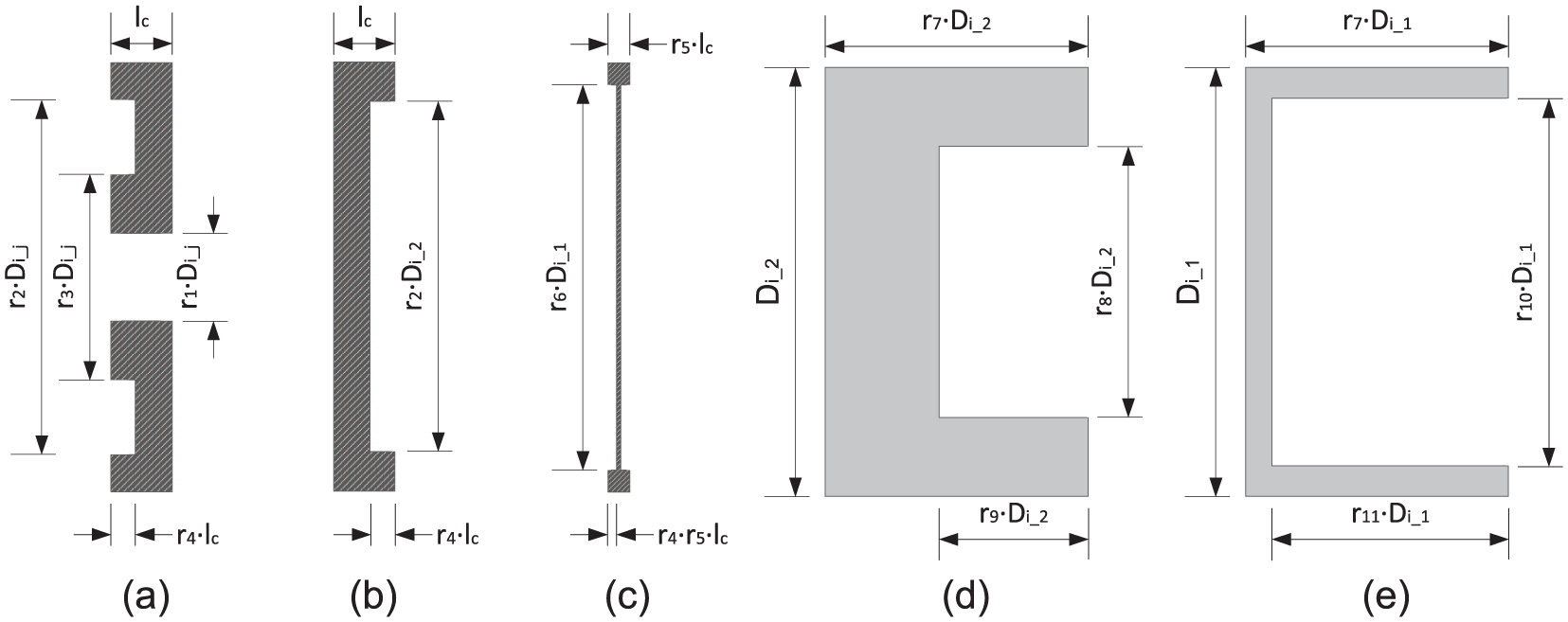
Schematic drawings of (a) the covers on the fluid side, (b) the cover on the gas side of the tip accumulator, (c) the cover on the gas side of the root accumulator, (d) the piston of the tip accumulator and (e) the piston of the root accumulator, based on Lauer (2015).
The mass of the cover on the fluid side depends on the respective inner diameter, the ratios r1 to r4 and the constant length of the cover, lc (see Appendix 2). Equation (5) can be simplified to equation (6) with which the mass of the covers on the fluid side can be computed for variable inner diameters

The cover on the gas side of the tip accumulator is similar to the cover on the fluid side, except there is no hole for the connection of the hydraulic tube (see Figure 4(b)). Hence, it can be calculated by equation (7)

The root accumulator it is under ambient air pressure, due to several small holes in its cover on the gas side. Consequently, its length is decreased by r5 in order to save weight and material (see Figure 4(c)). Its stationary mass, mcg_1, is therefore

Pistons
All pistons are made of aluminium with density ρp (as listed in Appendix 2). A recess on the gas side of the piston reduces its weight to a minimum (see Figure 4(d)). The length of the piston is not constant but varies with the inner diameter. Consequently, the mass of the piston of the tip accumulator can be calculated by equation (9) using ratio r7 to r9 (see Figure 4(d))

As the piston in the blade root accumulator is under ambient pressure, its recess is slightly greater, and thus its mass, mp_1, is calculated by applying r7, r10 and r11 (see Figure 4(e))

FW configurations
The number of tip accumulators, their position along the blade and their lengths determine the FW inertia and the total mass of the hydraulic system per blade. At first, the blade is assumed to be infinitely stiff, that is, the deflection of the blade is not considered and the maximum permissible length of a piston accumulator is the only limiting factor. As a result, several theoretical configurations differing in position of the tip accumulator, length of the tip accumulator and total mass of the hydraulic system per blade are derived.
As a rotor blade bends during operation, the bending of the blade at maximum tip deflection is considered in the investigation of possible FW configurations. Consequently, several theoretical configurations appear to be not feasible. Hence, parallel and serial packaging of tip accumulators is examined in order to avoid undesired interference of the blade with the piston accumulators.
Configurations for an infinitely stiff rotor blade
Computing the increase in inertia, the respective total mass of the hydraulic system per blade and the length of the tip accumulator is an iterative process as depicted in Figure 5. This iteration is done for all radii between Rsmall and tip radius with a step size of ΔR = 0.1 m (see outer loop on the left-hand side of Figure 5).
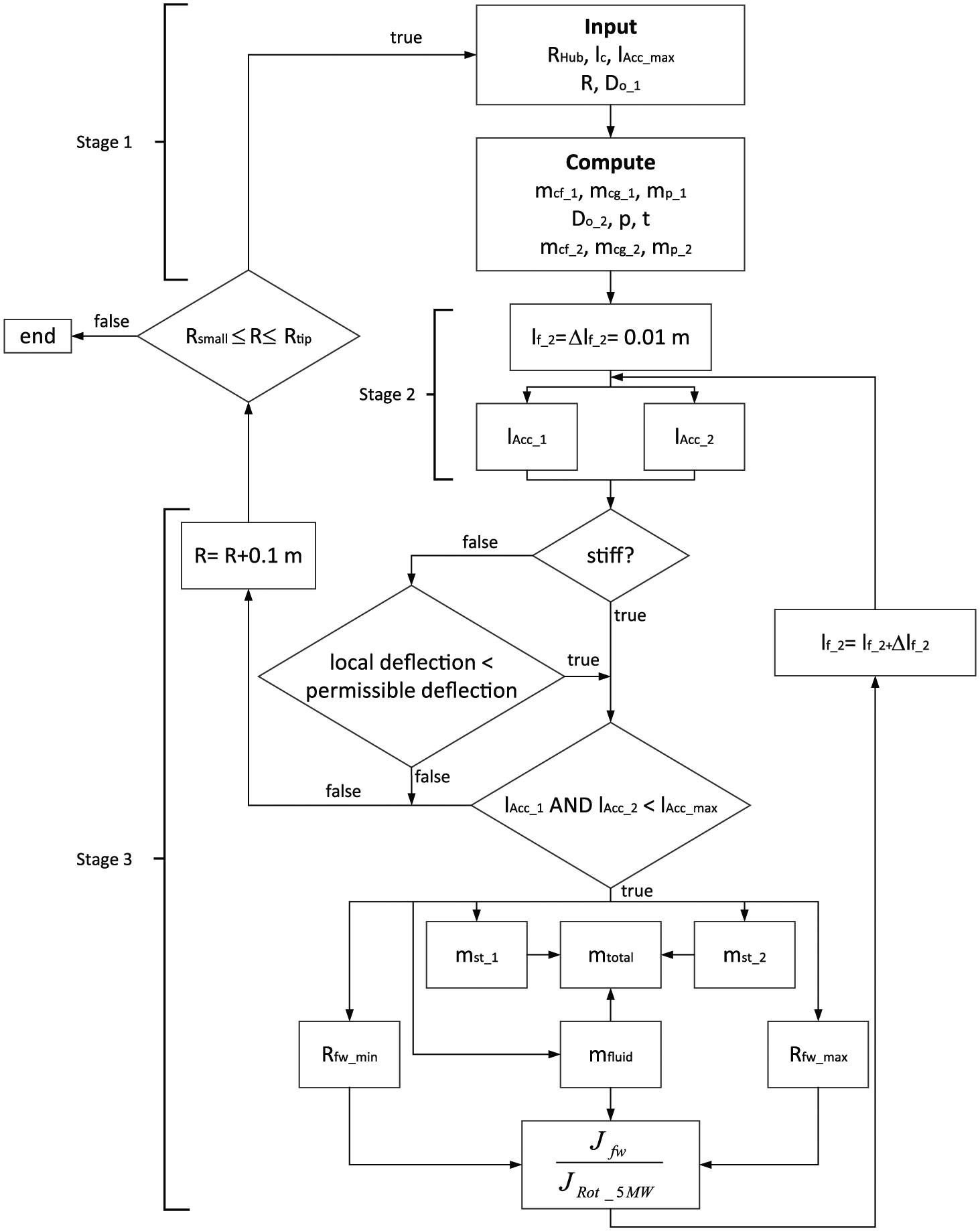
Iterative process for computing the increase in rotor inertia of the 5-MW WT, respective total mass of the hydraulic system per blade and total length of the tip accumulator.
Stage 1
At first, some input parameters are set constant such as the hub radius, RHub, the length of the cover, the maximum permissible length of a piston accumulator and the outer diameter of the root accumulator from which the inner diameter is calculated. The constant masses of the cover on the fluid side, the cover on the gas side and the piston of the root accumulator are computed according to equations (6), (8) and (10).
The outer diameter of the tip accumulator and the hydraulic pressure determine the required thickness of the steel shell of the piston accumulators. As mentioned above, the hydraulic pressure depends, among other things, on the rotor radius. The outer diameter of the tip accumulator decreases towards the blade tip (see Figure 3). However, the hydraulic pressure increases with increasing rotor radius (Jauch and Hippel, 2015).
Applying equation (3) for all possible outer diameters and resulting hydraulic pressures of the Resor blade and the NREL WT lead to a required thickness between 1.3 and 2.6 mm. As the required thickness is predominantly greater than 2 mm, it is a conservative assumption to set the wall thickness to t = 3 mm for all configurations. The resulting inner diameter is used to compute the stationary masses of the covers and piston of the tip accumulator by equations (6), (7) and (9).
Stage 2
The length of the fluid volume, lf_2, is initially set to the value of the step size, Δlf_2 = 0.01 m, and thus the length of the fluid volume of the root accumulator, lf_1, is computed as follows
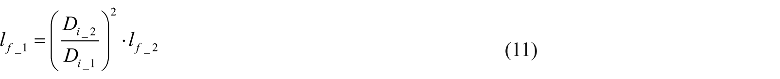
As a result, the total length of the piston accumulators can be calculated. It has to be noted that the total length includes not only the length of the fluid volume but also the length of the cover on the gas side, lcg_j, the length of the cover on the fluid side, lcf_j, and the length of the piston, lp_j (see Figure 6).
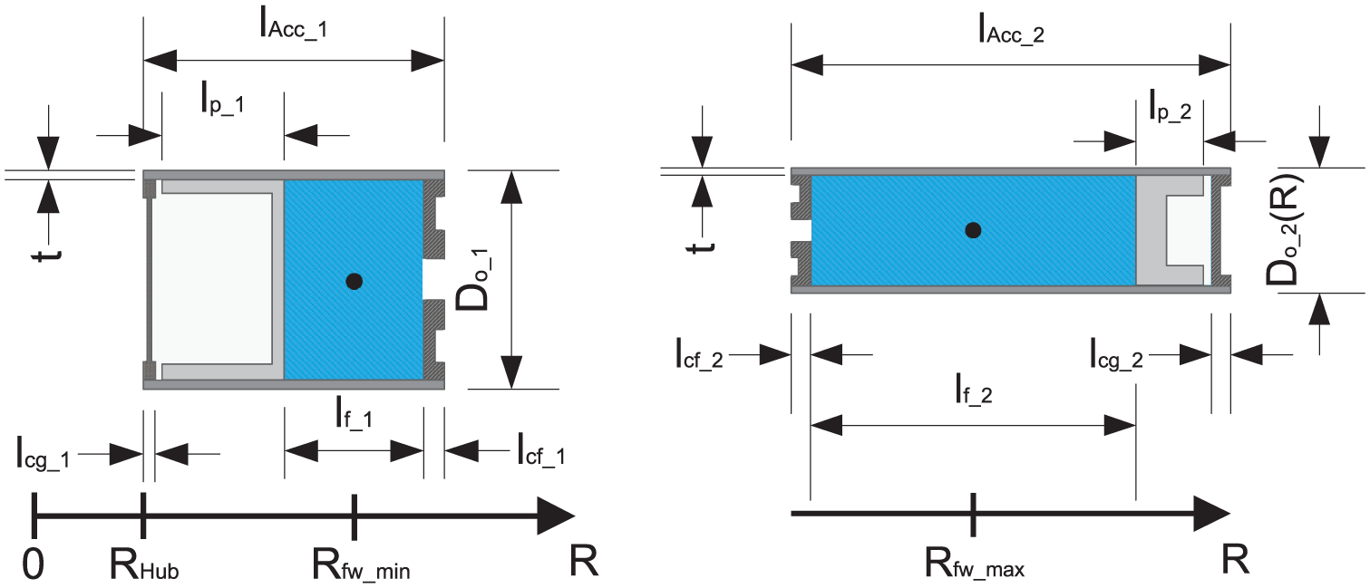
Left: Dimensions of a root accumulator of a discharged FW. Right: Dimensions of a tip accumulator of a charged FW.
The gap between the covers on the gas side and the pistons is negligibly small. This length of the gas volume within the piston accumulators, lgas, only ensures the piston not hitting the cover. A piston accumulator normally consists of a fluid volume and a much greater gas volume, whereby the piston accumulator becomes unfavourably long. The required gas volume of the FW system is therefore stored in gas bottles in the blade root. In doing so, the total length of the tip accumulator is minimized and its weight is decreased substantially (Hippel and Jauch, 2015). Consequently, the total lengths of the piston accumulators can be calculated by equation (12) (see Figures 4 and 6)

Stage 3
When the blade is assumed to be infinitely stiff, the iteration is proceeded, if the total lengths are smaller than the maximum permissible length of a piston accumulator (see Figure 5). Subsequently, the masses of the steel shells and thus the stationary masses of the piston accumulators can be computed by equations (4) and (2), respectively. The mass of the fluid is calculated by equation (13)

Consequently, the total mass of the hydraulic system per blade can be calculated as the sum of stationary masses and the fluid mass

The smallest and largest radius is derived by equations (15) and (16) (see Figures 4 and 6)


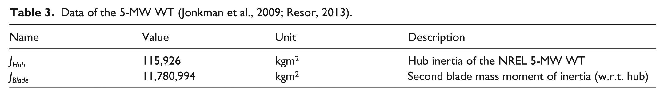
The resulting FW inertia (see equation (1)) is related to the rotor inertia of the 5-MW WT. The rotor inertia comprises the inertia of the hub, JHub, of the NREL WT and three times the inertia of the Resor blade with respect to the hub, JBlade (see Appendix 3). Finally, the length of the fluid volume of the tip accumulator is increased (see inner loop on the right-hand side of Figure 5) and the calculations above (equations (12) to (16)) are done as long as the maximum permissible length is not exceeded. If the condition concerning the length of the piston accumulators becomes false, the radius is increased and the iteration process starts from the beginning as long as Rsmall ≤ R ≤ Rtip.
Figure 7 shows the results of the iteration for the NREL WT and the Resor blade when the maximal permissible length of a piston accumulator is the only termination condition of the iteration. The graph on the left-hand side shows the required length of a tip accumulator for a certain increase in rotor inertia of the 5-MW WT. The graph on the right-hand side shows the respective total mass of the hydraulic system per blade of the configurations.
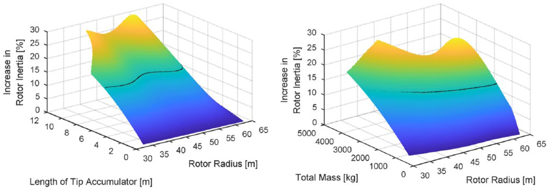
Left: Increase in rotor inertia of the 5-MW WT as a function of rotor radius and length of tip accumulator. Right: Increase in rotor inertia of the 5-MW WT as a function of rotor radius and total mass of the hydraulic system per blade.
Between a rotor radius of 33.5 and 41.5 m, the diameter of the tip accumulator is greater than the diameter of the root accumulator (see Figure 3). Consequently, the length of the root accumulator exceeds the maximum permissible length in order to contain a certain fluid mass. Hence, the iteration depicted in Figure 5 is stopped causing a gap in the graph on the left-hand side of Figure 7 for 7.6 m ≤ lAcc_2 ≤ 12 m and 33.5 m ≤ R ≤ 41.5 m.
For an infinitely stiff blade, the increase in rotor inertia is maximal (28.6%) at a rotor radius of 55.5 m for the maximal length of the tip accumulator. This results in a total mass of the hydraulic system per blade of 2357 kg. As a consequence, 1910 kg would be located in the flexible blade tip region when the FW is charged (see Figure 1, right).
However, the goal of this study is to examine configurations which increase the inertia of the rotor of the 5-MW WT by 15%. These configurations are represented by the horizontal lines in Figure 7 which are transformed to a two-dimensional plot (see Figure 8). This figure indicates that an inertia increase by 15% can be achieved by tip accumulators being shorter than the maximum permissible length.
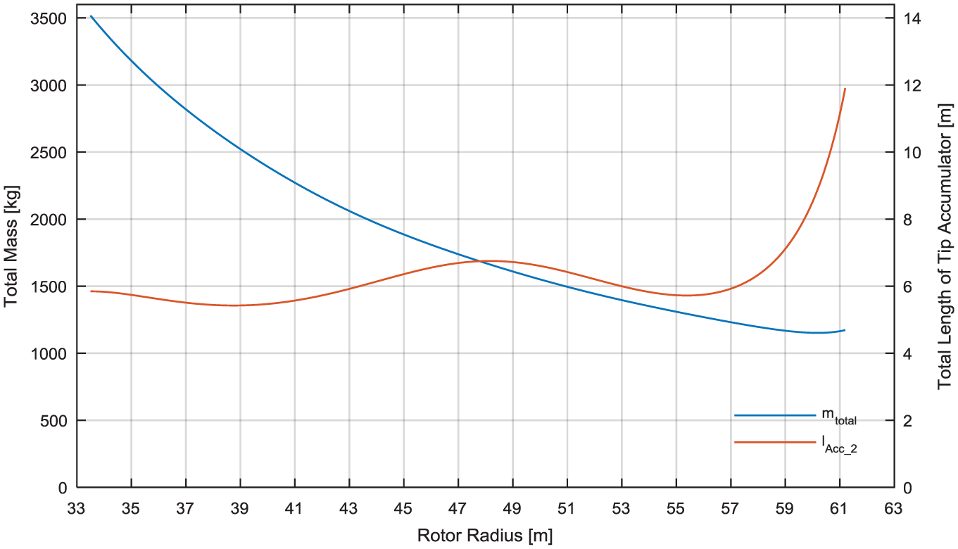
Total mass of the hydraulic system per blade and length of the tip accumulator for an increase in rotor inertia of the 5-MW WT by 15%.
The curve of the required length of the tip accumulator strongly depends on the curve of its outer diameter as shown in Figure 3. From 33.5 to 48.2 m rotor radius, the diameter decreases, and thus the length of the tip accumulator increases in order to contain enough fluid mass causing an increase in rotor inertia by 15%. From 48.2 to 55.4 m rotor radius, the pressure side and suction side are rather parallel to each other, and hence the length of the tip accumulator decreases. Starting at 55.4 m rotor radius, the blade narrows towards its tip, whereas the diameter strongly decreases and the length of the tip accumulator increases.
As shown in section ‘Derivation of stationary masses’, the masses of the covers and pistons depend on the second or third power of the inner diameter, respectively. Furthermore, the closer to the blade tip the less fluid mass is needed due to the increased largest radius of the FW system. As a result, the total mass of the hydraulic system decreases towards the tip but stagnates at around 60 m rotor radius. In this region of the blade, the total mass is mainly determined by the mass of the steel shell of the tip accumulator, which increases due to its great length. For rotor radii greater than 61.2 m, the tip accumulator would exceed the maximum permissible length, and hence no configurations are possible for this region of the blade.
However, a rotor blade is not infinitely stiff, but it bends due to external forces. In the following sections, the bending of the blade is applied to all possible configurations shown in Figure 7.
Configurations for a flexible rotor blade
A proper operation of the FW can only be ensured when the piston accumulators are not bent as this would prevent the moving of the piston. Hence, the FW should also be capable to operate when the rotor blade bends to its maximal extend. In order to derive configurations which are not affected by the deflection of the blade, the flapwise mode shape coefficients and the maximal out-of-plane tip deflection are needed.
The maximal out-of-plane tip deflection of the Resor blade equals 6.03 m and results from load simulations by Resor (2013). The out-of-plane deflection, DefOoP, along the rotor radius is computed by the flapwise mode shape coefficients and plotted with respect to the left y-axis in Figure 9. The thickness of the blade is defined by the courses of suction side and pressure side, xSS and xPS, which are plotted along the rotor radius with respect to the right y-axis. Positive values represent the suction side and negative values represent the pressure side of the rotor blade (also see Figure 2).
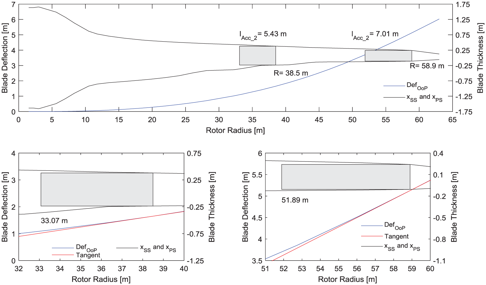
Top: Out-of-plane deflection of the Resor blade at maximal tip deflection, course of suction side and pressure side along the rotor radius and schematic drawing of tip accumulators causing an increase in rotor inertia of the 5-MW WT by 15%. Bottom (left to right): Zoom in of tip accumulators at 38.5 and 58.9 m rotor radius and tangent at out-of-plane deflection in the respective radius (38.5 or 58.9 m).
In order to visualize the correlation between permissible deflection and local deflection of the blade, two arbitrary tip accumulators are depicted as grey rectangles at different positions (38.5 and 58.9 m rotor radius). The respective lengths of the tip accumulators (5.43 or 7.01 m) are derived by Figure 8, and thus both configurations generate an increase in rotor inertia of the 5 MW WT by 15%.
The two graphs on the bottom of Figure 9 show an enlarged view of the tip accumulators being cantilevered at 38.5 or 58.9 m rotor radius. A tangent is drawn at these radii. Depending on their lengths, the tip accumulators reach up to a rotor radius of 33.07 and 51.89 m. The distance of the out-of-plane deflection to the tangent at these radii represents the local deflection of the blade at this certain radius. The distance from the outer wall of the tip accumulator at 33.07 or 51.89 m rotor radius to the pressure side (negative values) determines the permissible deflection.
As can be seen in the bottom left graph of Figure 9, the distance of the tip accumulator at 33.07 m rotor radius to the pressure side is greater than the difference of out-of-plane deflection and tangent. As a result, the tip accumulator will not be bent, and thus this configuration can increase the rotor inertia of the 5-MW WT by 15%.
A piston accumulator installed at 58.9 m rotor radius is longer, but the total mass of this configuration is more than halved compared to the latter configuration (see Figure 8). However, the right graph on the bottom of Figure 9 indicates that there is only a tiny distance between the tip accumulator at 51.89 m rotor radius and the pressure side because pressure side and suction side are quite parallel in this region of the blade. Consequently, the local deflection is greater than the permissible deflection, and thus the tip accumulator would be bent if the blade is maximally deflected.
When the rotor blade is not infinitely stiff, the local deflection is compared to the permissible deflection (see Stage 3 in Figure 5). In the latter example, this condition becomes false, and thus the rotor radius is increased and the iteration starts from the beginning. When the local deflection is smaller than the permissible deflection, the lengths of the piston accumulators are checked. As long as these two condition blocks are true, the iteration is proceeded and terminates as soon as one condition becomes false. As a result, the condition concerning the deflection of the blade becomes false for a significant number of configurations, and thus the iteration is stopped (compare Figure 10 to Figure 7).
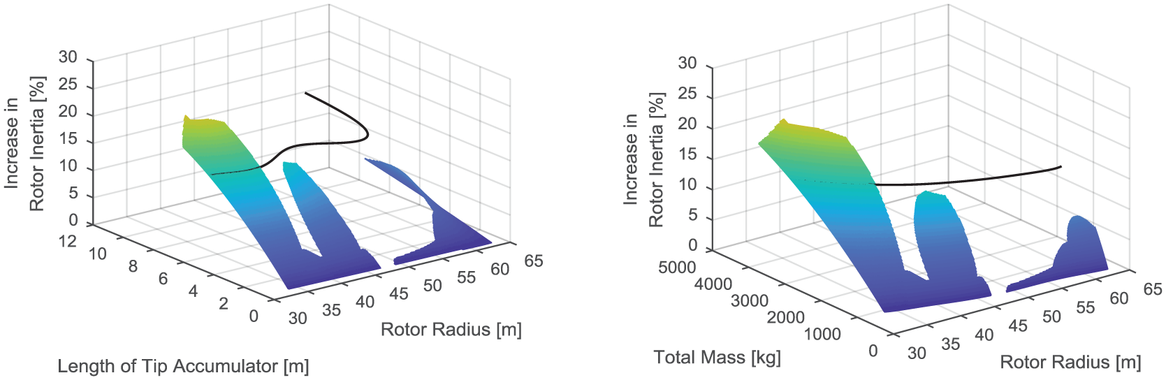
Left: Increase in rotor inertia of the 5-MW WT as a function of rotor radius and length of tip accumulator for a maximal out-of-plane deflection of 6.03 m. Right: Increase in rotor inertia of the 5-MW WT as a function of rotor radius and total mass of the hydraulic system per blade for a maximal out-of-plane deflection of 6.03 m.
Arranging two piston accumulators in a conventional way (see Figure 1), hereafter named as Type I (see Figure 11, left), 15% increase in rotor inertia of the 5-MW WT is only achieved using a tip accumulator at radii smaller than 40.1 m (see horizontal line in Figure 10). As a downside, the resulting total mass of the hydraulic system per blade is high due to the great diameters and high required fluid mass (see Figure 10, right).
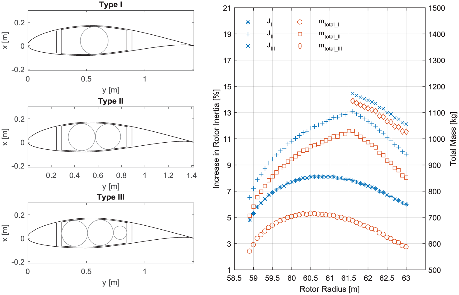
Left (from top to bottom): Blade section at 61.63 m rotor radius with one tip accumulator (Type I), two tip accumulators (Type II) or three tip accumulators (Type III) between the SWs. Right: Resulting increase in rotor inertia of the 5-MW WT and respective total mass of the hydraulic system per blade for Type II and Type III compared to Type I.
In the following sections, it is analysed whether the rotor inertia of the 5-MW WT can be increased by 15% using more than one tip accumulator. The potential benefit of this approach is evaluated by comparing the total mass of the hydraulic system per blade. For the Resor blade, the lightest configuration of Type I causing an increase in rotor inertia by 15% implies one 5.48 m long tip accumulator installed at 40.1 m rotor radius causing a total mass of the hydraulic system per blade of 2379 kg. Hence, a configuration with more than one tip accumulator leading to a smaller total mass of the hydraulic system per blade can be feasible.
Parallel packaging of piston accumulators
Installing more than one tip accumulator within the blade side by side is called parallel packaging and was previously presented (Hippel and Jauch, 2015). However, in this previous study, the resulting stationary masses of the piston accumulators were not considered. In the following sections, it is analysed whether parallel packaging leads to 15% inertia increase and at the same time cause a smaller total mass of the hydraulic system per blade than the lightest configuration of Type I.
Optimal use of available space in the blade tip region
Installing one tip accumulator (Type I) in the blade tip region, that is, from 58.9 to 63 m rotor radius, the goal of 15% inertia increase is not achieved (see Figure 10, left). The increase in rotor inertia of the 5-MW WT is limited to 8.1% (see JI in Figure 11, right).
In the blade tip region, the distance of pressure side to suction side is small, whereas the distance between the SWs is rather constant. Consequently, parallel packaging can be applied between the SWs (see Figure 11, left, Type II and Type III). Applying Type II or Type III arrangement in the blade tip region enhances the increase in rotor inertia of the 5-MW WT and increases the total mass of the hydraulic system per blade (see JII–JIII and mtotal_II–mtotal_III in Figure 11, right). However, the desired goal of 15% inertia increase is not achieved.
The rotor inertia can be further increased by installing a tip accumulator in the leading edge (see Type IV and Type V in Figure 12, left). The increase in inertia and total mass of Type I, Type IV and Type V is shown in Figure 12 (right). It reveals an increase in rotor inertia, JIV, greater than 15% between 60.3 and 62.2 m rotor radius for configurations of Type IV. Arranging four accumulators as Type V, 15% inertia increase is exceeded for all radii.
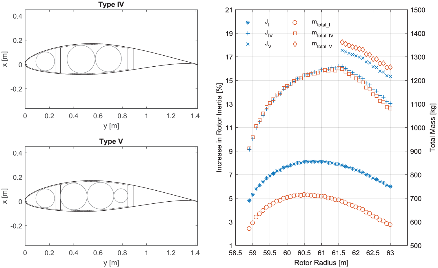
Left (top): Parallel packaging of Type IV at 61.63 m rotor radius. Left (bottom): Parallel packaging of Type V at 61.63 m rotor radius. Right: Resulting increase in rotor inertia of the 5-MW WT and respective total mass of the hydraulic system per blade for Type IV and Type V compared to Type I.
For all configurations of Type IV and Type V exceeding 15% inertia increase, the length of the tip accumulators is truncated, that is, the fluid mass is decreased until the inertia increase corresponds to 15% of the rotor inertia of the 5-MW WT. The lightest configuration of Type IV implies three tip accumulators (5.97, 5.96 and 5.92 m) installed at 61.6 m rotor radius causing a total mass of the hydraulic system per blade of 1172 kg. The total mass is therefore reduced by more than 50% compared to the lightest configuration of Type I. Truncating Type V accumulators decreases the total mass of the hydraulic system per blade, but it is still greater than the total mass of Type IV arrangement.
Parallel packaging between 40.7 and 46.7 m rotor radius
As parallel packaging in the blade tip region leads to lighter FW configurations than arranging piston accumulators as Type I, it can also be beneficial in other regions of the blade. As can be seen in Figure 10 (left), the increase in rotor inertia of the 5-MW WT is close to the desired value of 15% for configurations around 44 m rotor radius.
In this region of the blade, the distance of pressure side to suction side is only slightly smaller than the distance of the SWs (comparable to the graph on the top of Figure 2, right). Consequently, it is not beneficial to arrange tip accumulators as Type II or Type III. However, a second tip accumulator can be installed in the leading edge parallel to the accumulator between the SWs. This arrangement is called Type VI in the following.
In order to enhance the inertia increase to 15%, additional fluid mass is required. The computed additional fluid mass determines the diameter and hence the stationary masses of the leading edge tip accumulator. The optimal configuration of Type VI arrangement implies two tip accumulators (5.05 and 4.92 m) installed at 46.6 m rotor radius causing a total mass of the hydraulic system per blade of 1813 kg. The total mass of this arrangement type is obviously greater than applying parallel packaging in the blade tip (Type IV), but it is lower than the total mass of the lightest configuration of Type I.
Serial packaging of piston accumulators
The blade region between 40.7 and 46.7 m rotor radius can also be optimized by applying serial packaging of piston accumulators. An additional piston accumulator is installed at tip radius and designed for providing the required fluid mass in order to enhance the inertia increase to 15% (see Figure 13, left, Type VII). Installing the additional piston accumulator in the blade tip has two major advantages: First, the stationary masses of its covers and pistons are minimal, because the possible diameter is at its minimum (see Figure 3). Second, the largest radius of the FW system is maximized, and hence the additional fluid mass is minimal.
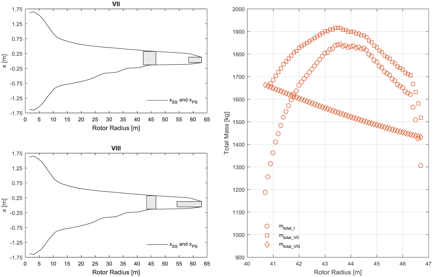
Left (top): Serial packaging in order to compensate the lack in FW inertia (Type VII). Left (bottom): Serial packaging with maximal length of second tip accumulator (Type VIII). Right: Resulting total mass of the hydraulic system per blade for Type VII and Type VIII compared to Type I.
For all configurations between 40.7 and 46.7 m rotor radius, the required additional fluid mass and thus the dimensions and stationary masses of an additional tip accumulator are computed. The lowest total mass of the hydraulic system per blade for arrangement Type VII is achieved at 46.7 m rotor radius (see mtotal_VII = 1518 kg in Figure 13, right). A piston accumulator with a total length of 4.52 m (see thick rectangle in Figure 13, left, Type VII) is initially installed at this radius causing an increase in rotor inertia by 10.4%. Installing an additional tip accumulator (Di_2add = 176 mm, lAcc_2add = 4.64 m) at the radius of the blade tip (see thin rectangle in the same plot), the increase in inertia is enhanced to 15%. The largest radius of the FW system applying serial packaging, Rfw_max_SP, increases according to equation (17)
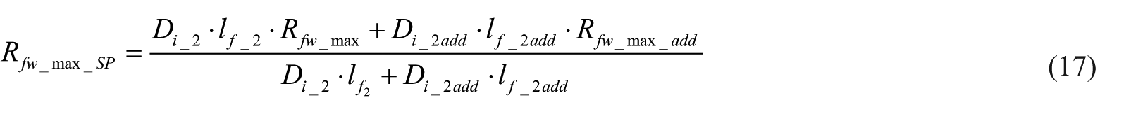
The lengths of the fluid volume of the first tip accumulator and the additional tip accumulator, lf_2add, can be computed by rearranging equation (12). The largest radius, Rfw_max_add, is the centre of gravity of the fluid within the additional tip accumulator and is calculated by equation (16).
The greater the largest radius of the FW system applying serial packaging, the less fluid mass is required, and hence the stationary mass of the steel shell decreases. According to equation (17), the largest radius increases when the length of the fluid volume of the additional tip accumulator is maximal. The total length of the additional tip accumulator at 63 m rotor radius is limited to 8.75 m by the maximal local deflection of the blade. As a result, the largest radius of the FW system applying serial packaging is maximized, and hence fluid mass can be removed from the first tip accumulator at 46.7 m rotor radius. Consequently, it can be truncated (see thick rectangle in Figure 13, left, Type VIII), and thus the stationary masses of the root and first tip accumulator are decreased. The optimal configuration of Type VIII arrangement implies two tip accumulators (3.31 and 8.75 m) installed at 46.7 and 63 m rotor radius causing a total mass of the hydraulic system per blade of 1433 kg.
Evaluation of FW configurations
There are several possibilities for arranging piston accumulators within a rotor blade (Type I to Type VIII). The arrangement types differ in four design criteria: number of tip accumulators, position of tip accumulators within the rotor blade, length of tip accumulators and total mass of the hydraulic system per blade. Table 1 summarizes the lightest FW configurations for the Resor blade causing an increase in rotor inertia of the 5-MW WT by 15%.
Lightest FW configurations leading to an increase in rotor inertia of the 5-MW WT by 15%.
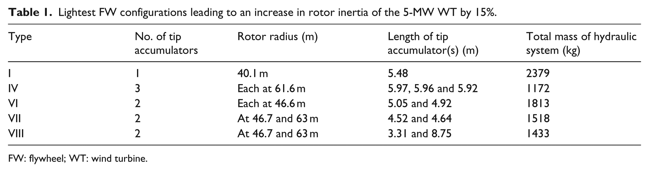
FW: flywheel; WT: wind turbine.
Conclusion and outlook
The study of the article at hand is significant for the further development of the proposed FW system. The methodology of analysing the internal dimensions of a rotor blade, deriving the stationary masses of the hydraulic components and the FW configurations is done for Resor’s blade model and the NREL 5-MW WT as their data are publicly available. These analyses can obviously be applied to any other arbitrary rotor blade and WT.
A main finding is that the initial design of the FW system (Type I) is not feasible for the majority of configurations due to the flexible behaviour of the blade. Packing tip accumulators in parallel or serial increases the rotor inertia of the 5-MW WT by 15% and cause a lower total mass of the hydraulic system per blade than applying arrangement Type I.
As a result, there is a variety of configurations which cause an increase in rotor inertia of the 5-MW WT by 15%. The weight-optimized FW configuration for the Resor blade and the 5-MW NREL WT implies installing three tip accumulators of approximately 6 m length at 61.6 m rotor radius. Hence, the additional mass due to the FW system is mainly installed within the flexible blade tip region. Arranging one tip accumulator (Type I) at 40.1 m rotor radius requires almost twice as much total mass.
In the future, the additional loads on the whole WT due to the FW system are analysed for the different configurations leading to 15% inertia increase. Consequently, it can be stated which configuration will have the lowest influence on the WT in terms of mechanical loads.
The stationary masses computed in this study are derived from an initial design of a hydraulic system by HYDAC (Lauer, 2015). Conventional hydraulic components such as covers and piston are designed for high pressures (up to 350 bar) and are made of steel and aluminium, respectively. However, the resulting hydraulic pressure of all possible FW configurations for the 5-MW NREL WT does not exceed 50 bar. Hence, future work will need to focus on designing the hydraulic components suitable for the FW system. Light-weight accumulators are already used in the aircraft industry, however, for small volumes only. They will need to be developed further in order to suit the FW system in a WT rotor. As a result, the total mass of the FW system and the impact on the mechanical loads of the WT will be minimized.
Footnotes
Appendix 1
Appendix 2
Dimensioning ratios derived by previously designed hydraulic system, material densities of hydraulic components and constant length of cover (Lauer, 2015).
| Name | Value | Unit | Description |
|---|---|---|---|
| r1 | 10/49 | – | Ratio of tube diameter to inner diameter |
| r2 | 40/49 | – | Ratio of outer diameter of circular ring of cover on the fluid side to inner diameter |
| r3 | 235/490 | – | Ratio of inner diameter of circular ring of cover on the fluid side to inner diameter |
| r4 | 28/70 | – | Ratio of depth of circular ring to constant length of cover |
| r5 | 25/70 | – | Ratio of length of cover on gas side of root accumulator to constant length of cover |
| r6 | 444/490 | – | Ratio of recess of cover on gas side of root accumulator to its inner diameter |
| r7 | 30/49 | – | Ratio of length of piston to inner diameter |
| r8 | 31/49 | – | Ratio of piston recess diameter to inner diameter of the tip accumulator |
| r9 | 17/49 | – | Ratio of piston recess length to inner diameter of the tip accumulator |
| r10 | 42/49 | – | Ratio of piston recess diameter to inner diameter of the root accumulator |
| r11 | 27/49 | – | Ratio of piston recess length to inner diameter of the root accumulator |
| ρs | 7850 | kg/m³ | Density of the steel shell |
| ρp | 2710 | kg/m³ | Density of the aluminium piston |
| ρc | 7840 | kg/m³ | Density of the steel covers |
| ρf | 1000 | kg/m³ | Density of the fluid |
| lc | 0.070 | m | Length of the cover |
Appendix 3
Data of the 5-MW WT (Jonkman et al., 2009; Resor, 2013).
| Name | Value | Unit | Description |
|---|---|---|---|
| JHub | 115,926 | kgm2 | Hub inertia of the NREL 5-MW WT |
| JBlade | 11,780,994 | kgm2 | Second blade mass moment of inertia (w.r.t. hub) |
Declaration of conflicting interests
The author(s) declared no potential conflicts of interest with respect to the research, authorship and/or publication of this article.
Funding
This work was supported by the Gesellschaft für Energie und Klimaschutz Schleswig-Holstein GmbH (EKSH).