
Abstract
In this article, the control strategy for a previously proposed flywheel system that is integrated in a wind turbine rotor is presented. This control strategy allows the flywheel system to serve two purposes: support of the frequency in the grid and mechanical load mitigation in the wind turbine. For the first purpose, extra energy is fed into the grid whenever there is a contingency; alternatively, the varying power output from the wind turbine can be stabilized. For the latter purpose, the flywheel is applied to detune the eigenfrequency of the most vibratory components in a wind turbine, that is, the rotor blades. Simulations are shown to illustrate the principle and the performance of the proposed system. It is concluded that the controls of the flywheel system manage to support the grid frequency and also mitigate mechanical vibrations in different operating points of the wind turbine.
Introduction
The transition from conventional to renewable power generation demands new approaches to how security of supply can be maintained. The volatile infeed from renewable power sources like wind power makes the task of maintaining the balance between generation and consumption in an alternating current (AC) power system even more challenging. In addition to this, the power plants that traditionally took on this task, that is, conventional control power plants, are substituted by renewable power plants.
Hence, new technologies that allow renewable power plants to contribute to the control of the power system are needed. The current grid codes require wind turbine (WT) generators to contribute to the power system inertia and hence to the support of primary frequency control by performing synthetic inertia. This approach has a major downside in that it impacts on the rotational speed of the WT rotor and by doing so drives the WT into a sub-optimal operating point (Asmine and Langlois, 2014; Díaz-Conzález et al., 2014; Duckwitz et al., 2014).
Previous work of the author presented the system of a flywheel in a WT rotor that circumvents this problem. Initially, this flywheel was proposed to be designed as a mechanical weight positioning system (Jauch, 2015). This technology has been developed further such that it is now designed as a hydraulic-pneumatic system that is integrated in the rotor blades of the WT (Jauch and Hippel, 2015).
Based on these descriptions of the functionality of the flywheel, in the article at hand the controls for such a hydraulic-pneumatic flywheel system are presented. The different control modes and also the different control purposes are discussed. While in the past the primary purpose of such a system was the contribution to power system inertia, here also the purpose of mechanical load mitigation is discussed. Both purposes interact with each other, as the flywheel can be applied in different operating points of the WT. This has an impact on the energy that can be exchanged with the flywheel and on the excitation of mechanical vibrations in the WT.
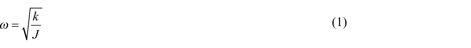
As described in previous work, the flywheel in a WT rotor varies its inertia in order to store or release energy (Jauch, 2015). By doing so, the inertia of not only the flywheel but also the rotor blades, the whole rotor and eventually the entire drive train is varied. Equation (1) illustrates that the inertia, J, impacts on the resonance frequency, ω, of a torsional oscillator, where k is the torsion stiffness. Hence, the flywheel can impact on the eigenfrequency of a WT, and by doing so it can be used for circumventing critical excitations that inevitably occur during operation
During the operation of a WT, excitations to mechanical vibrations cannot always be avoided. However, vibrations only become hazardous when their magnitudes exceed critical levels, or when they persist for too long. Hence, WTs must not dwell for too long in critical excitations as this allows vibrations to develop large magnitudes. Vibrations with large magnitudes are extreme loads. Even vibrations with moderate magnitudes contribute noticeably to fatigue loads when they persist for longer time.
The conventional approach to mitigating vibrations is damping. The most effective means of damping torsional vibrations is to control the electric torque of the generator via the frequency converter (Wright and Fingersh, 2008).
The most flexible components in a WT are the rotor blades. Hence, damping torsional vibrations of the drive train, that is, also in-plane vibrations of the blades, are possible but not easy to achieve with the generator torque. Band-pass filters or state feedback control can be applied (Licari et al., 2015).
The other critical vibration of rotor blades is in out-of-plane direction. It is difficult to tackle these vibrations with the generator torque, since the only connection between torque and out-of-plane motion is the aerodynamics.
Multivariable state control can be used in order to mitigate loads by applying the different actuators in a WT (Ritter et al., 2015). This approach implies the risk that in the attempt to damp vibrations in one state variable, vibrations in another are excited (Wright and Fingersh, 2008).
A more effective means of controlling the loads arising from the rotor blades is to control the aerodynamics directly. There are different methods conceivable (Barlas and Van Kuik, 2010). Although these methods have been discussed for some years already, many of them have not yet reached a technology readiness level (TRL) that allows entering the WT market. However, in addition to the load mitigating effect, some of these methods also lead to an increased energy yield, which makes them economically attractive.
Alternatively, vibrations in the different WT components can be mitigated with tuned mass dampers (ESM Energie- und Schwingungstechnik Mitsch GmbH, 2015; Si and Karimi, 2015). These have shown to mitigate vibrations in WT towers (Hanus and Glanzner, 2015) and can also be applied in other components like rotor blades. However, such equipment needs space in the WT, adds to the cost and weight of the WT and does not produce an extra benefit for the WT owner.
Hence, it is obvious that mechanical vibrations should be avoided in the first place, rather than damped when they have developed. For this purpose, the eigenfrequency of the rotor blades can be varied, that is, detuned deliberately with the flywheel, such that a given excitation does not lead to vibration with harmful magnitude.
Therefore, the control strategy of a flywheel in a WT rotor has to serve the purpose of grid frequency support and also the purpose of avoiding mechanical vibrations.
In the following sections, first the simulation model is introduced. Subsequently, the layout of the control system that serves both purposes is described. Simulations are shown to illustrate the behaviour and performance of the system. Finally, a conclusion is drawn and possible future developments are indicated.
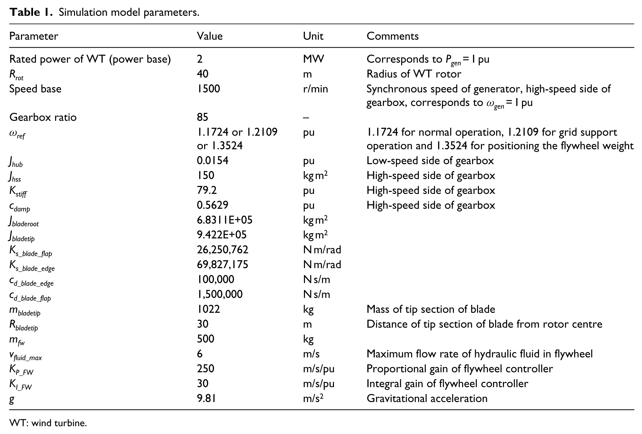
In this article, the per unit (pu) representation of quantities is applied. This is common practice in power system studies and is particularly handy when comparing signals. For example, a power in pu directly yields the level of loading of a machine. WTs of different ratings become comparable in terms of their operating point, although the active power that they feed into the grid might vary by orders of magnitude. When referring to rotational speed in a WT, the generator speed, the speed of the low speed shaft and the circumferential speed of the tip sections of the rotor blades all become directly comparable if expressed in pu. In order to translate pu values to the values in SI units, the base values are given in Table 1 in Appendix 1.
There are obviously quantities where a pu representation does not make sense, like wind speed, pitch angle, out-of-plane motion and eigenfrequency. In these cases, SI units are applied.
WT simulation model
The WT model is based on the model used in previous work (Jauch, 2015), that is, it is a model of a 2-MW variable speed, pitch to feather WT. It has a conventional drive train with a gearbox and a fast spinning generator. Models of such WTs are described in great detail in the literature (Hansen A et al., 2003; Hansen MH et al., 2005; Sørensen et al., 2001, 2003). Therefore, only a block diagram showing the different subsystems of the WT model applied in this study is depicted in Figure 1.
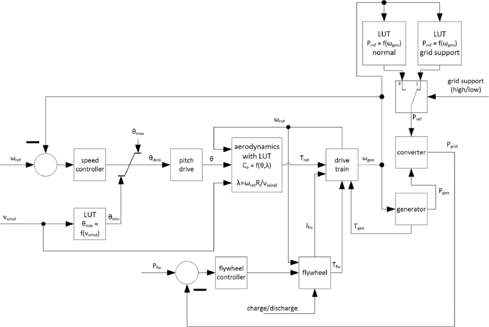
Block diagram of the WT model.
The simulation model is extended by the controls, which are discussed in this article. Figure 1 shows the block diagram, where the difference to the previous work (Jauch, 2015) is in the blocks ‘LUT Pref = f(ωgen) grid support’, ‘flywheel controller’, ‘flywheel’ and ‘drive train’. For details on the content of block flywheel, see Jauch and Hippel (2015). All the other extensions to the simulation model are discussed in the following sections.
The simulation model parameters are listed in Table 1 in Appendix 1. There the blade parameters are given in terms of flapwise and edgewise. In the model, these parameters are transformed to out-of-plane and in-plane taking the pitch angle into account, as discussed in section ‘Rotor model’.
Regarding the choice of WT dimensions, it has to be said that the rotor diameter of 80 m is comparably small for a 2-MW WT. This has been chosen deliberately to assure conservative assumptions. With longer rotor blades, the effect of the flywheel increases as the energy in the flywheel is a function of the square of the radius (Jauch, 2015). Also regarding the eigenfrequency of the rotor blades, the effect discussed in section ‘Mechanical load mitigation’ would become even more obvious with longer rotor blades.
Rotor model
Since avoidance of mechanical vibrations is one of the two tasks of the flywheel, the model of the rotor is elaborate to represent the first eigenfrequency of the blades in in-plane and out-of-plane directions. Hence, the content of block ‘drive train’ in Figure 1 is the representation of the rotor and the drive train as depicted in Figure 2. For the assessment of mechanical loads in WTs, it is common practice to use readily available simulation tools like Flex5 or Bladed. However, such tools cannot be used for simulating the behaviour of a WT with flywheel in the rotor, as these tools are not designed for the simulations with variable blade inertias. Therefore, the simulation model as described below is applied in this study.
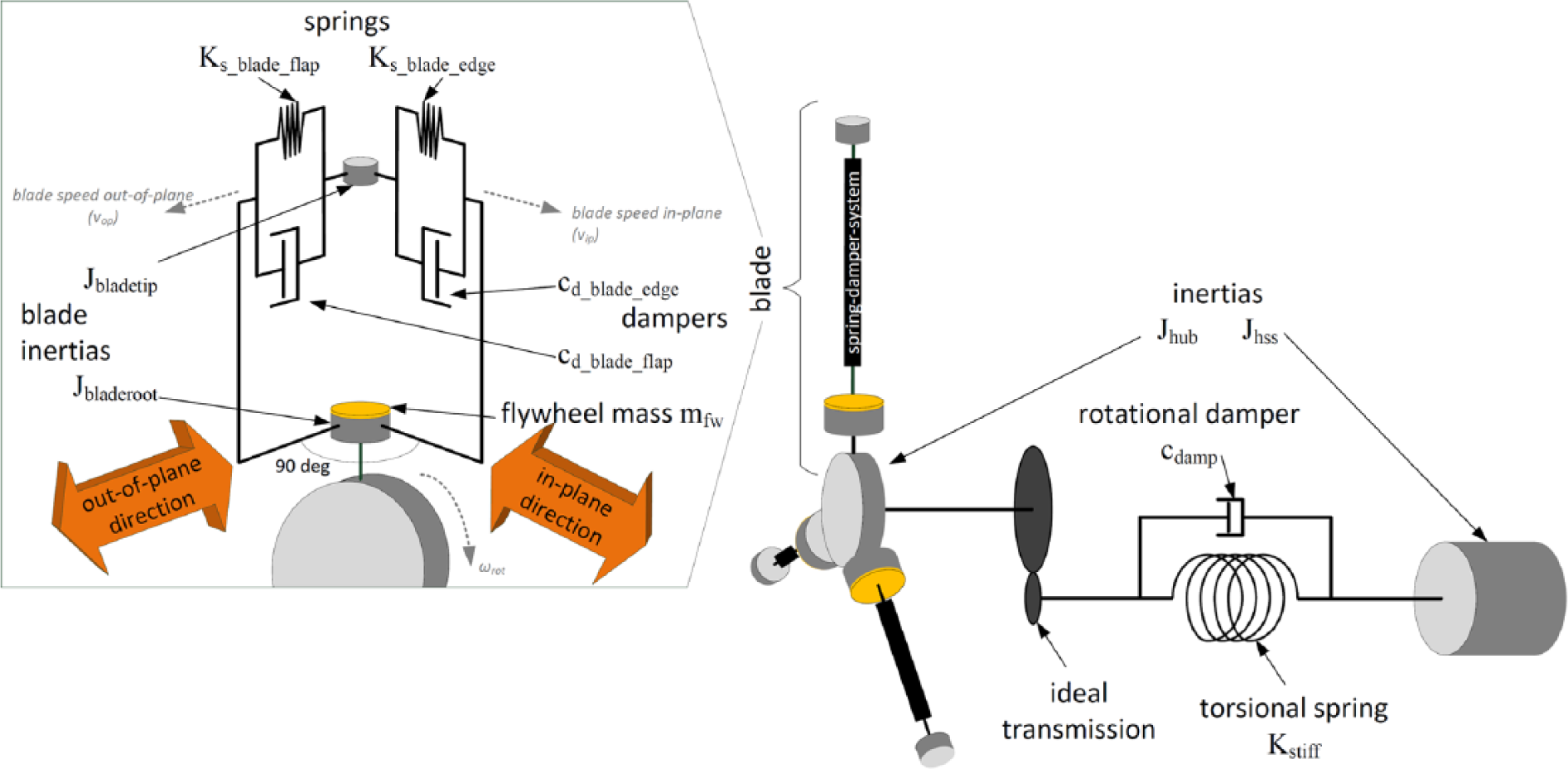
Combination of masses, springs and dampers that represent the vibratory behaviour of the drive train and the rotor. The flywheel is shown in discharged state. The dashed grey arrows in the rotor model represent the motion of the masses.
The equation system that describes the behaviour of the rotor blades (detailed depiction in Figure 2) is introduced in the following.
In in-plane direction, the driving torque Tdrive that acts on the tip section of one blade comprises the aerodynamic torque Trot and the torque from gravitational forces Tgravi

Tgravi is a function of the rotor angle, α, and the mass of the flywheel that acts on the tip section of the blade, mtank2. This mass is in the distance xAcc from the centre of rotation (Jauch and Hippel, 2015)

The flywheel weight and the mass of the tip section constitute an inertia, Jbladetip

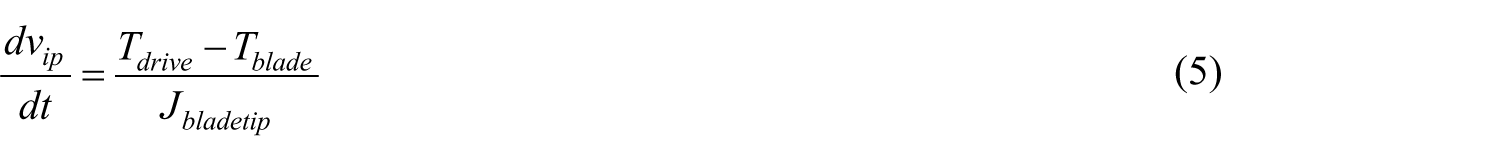
The acceleration of the tip section of the blade in in-plane direction, that is, the gradient in the speed vip, is defined by equation (5), where Tblade is the torque with which the blade impacts on the shaft that rotates with ωrot
Tblade is influenced by the deflection, defip, and the damping, dmpip, of the blade in in-plane direction

With defip defined by equation (7)

where Ks_ip is the stiffness of the blade in in-plane direction, which is derived from the edgewise stiffness, Ks_blade_edge, the flapwise stiffness, Ks_blade_flap, and the pitch angle, θ

Likewise, the in-plane damping, cd_ip, can be derived

This allows defining dmpip, which is needed in equation (6)

Similar to Tblade in in-plane direction, there is a torque in out-of-plane direction, Top, which arises from the deflection of the blade orthogonally to the rotor plane.
Also for deriving Top, the blade stiffness and damping parameters need to be translated from flapwise and edgewise to out-of-plane and in-plane using the pitch angle θ. The out-of-plane stiffness Ks_op is defined by equation (11) and the out-of-plane damping is defined by equation (12)


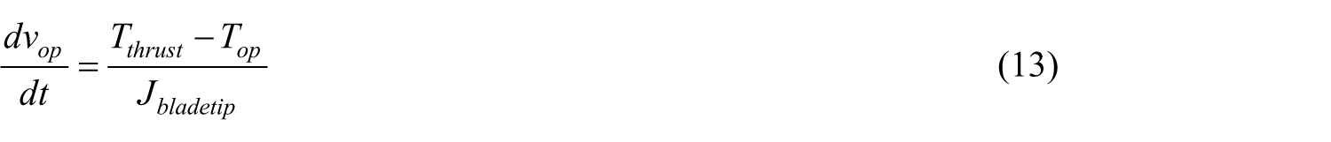
The acceleration of the tip section of the blade in out-of-plane direction, that is, the gradient in the speed vop, is defined by equation (13)
where Tthrust is the torque which arises from the thrust force and Top is the torque that arises from the bending of the blade in out-of-plane direction (equation (16)).
Tthrust is defined by equation (14), which shows that it is a function of the rotor radius, Rrot, the wind speed which is perceived by the tip section of the blade, vwind_bl, the air density, ρ, the aerodynamic thrust coefficient, Ct, and the distance of the tip section of the blade from the rotor centre, Rbladetip

The wind speed vwind_bl is the ambient wind speed, vwind, offset by the out-of-plane motion of the tip section of the blade, vop, which can be yielded by integrating equation (13). In order to get vop in the unit m/s, it needs to be multiplied by the radius of the circular trajectory, Rbladetip

Top comprises the deflection, defop, and the damping, dmpop, of the blade in out-of-plane direction

With defop and dmpop defined by equations (17) and (18), respectively


Hence, the behaviour of the blades in in-plane direction directly acts on the rotation of the shaft, while the motion in out-of-blade direction interacts with the wind speed. Therefore, it interferes with the rotation of the shaft indirectly via the aerodynamics.
Power versus speed characteristic
The content of the blocks ‘LUT Pref = f(ωgen) grid normal’ and ‘LUT Pref = f(ωgen) grid support’ (block diagram in Figure 1) is depicted in Figure 3.
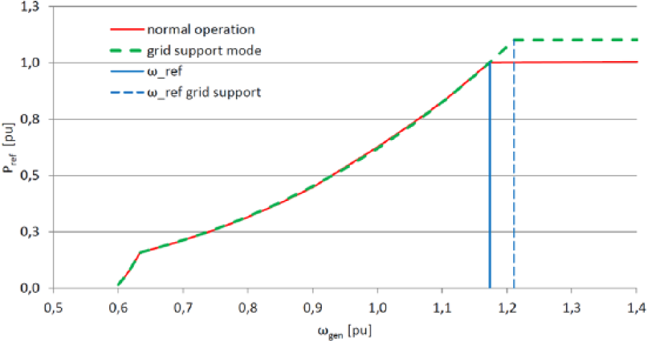
Power versus speed characteristics and corresponding speed references of the WT.
If the WT is in full-load operation, extra power for supporting the grid frequency can be yielded from the wind. This, however, requires that both the shape of the power versus speed characteristic and the setpoint for the speed controller (ωref in Figure 1) have to be adjusted. Hence, Figure 3 shows both power versus speed characteristics and both speed setpoints.
Flywheel controller
The flywheel controller in Figure 1 controls the speed with which the flywheel can be discharged. It is a proportional–integral controller whose gains KP_FW and KI_FW are given in Table 1 in Appendix 1. The maximum speed that can be achieved is limited by the flow rate of the hydraulic fluid, vfluid_max (Jauch and Hippel, 2015).
Control modes
To serve the two control purposes of grid frequency support and load mitigation, the flywheel controller is set up as a state machine, which is illustrated in the state diagram shown in Figure 4.
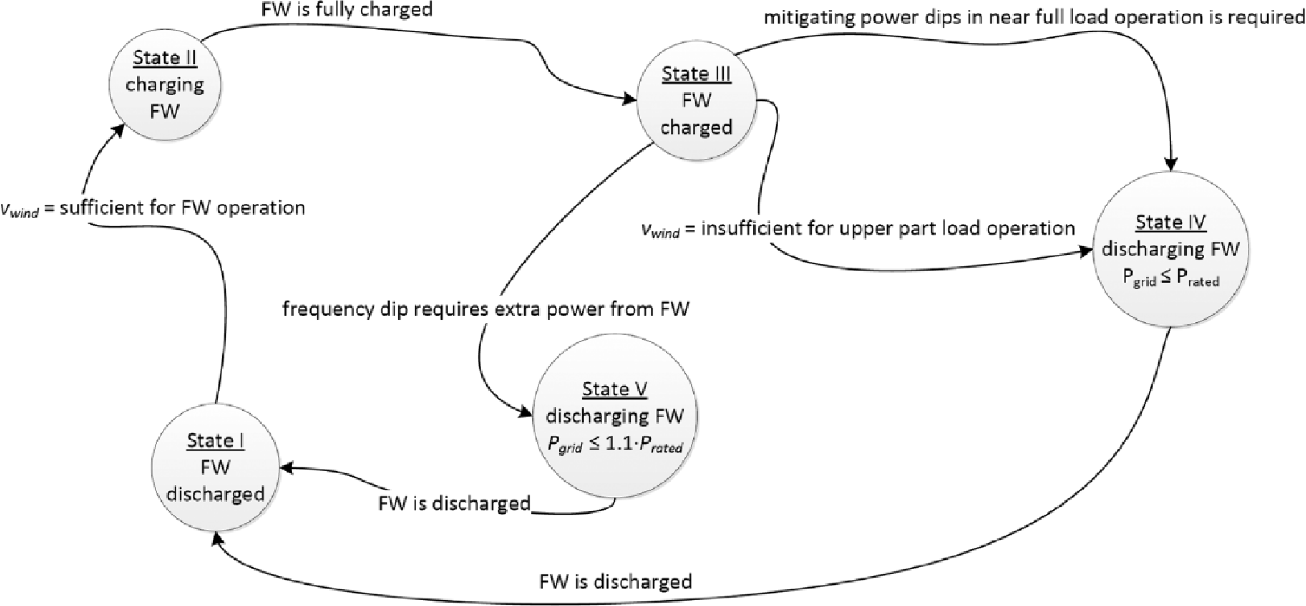
State diagram of flywheel controller.
The different states in which the flywheel controller can operate are discussed in the following sections.
Preparation of flywheel
When the flywheel is discharged, that is, when the weights are in the blade root as shown in Figure 2, the state machine is in State I, see Figure 4. In order to use the flywheel, it needs to get charged (State II) before it is available (State III).
As described in previous work, the flywheel is charged with centrifugal forces. In Jauch (2015), an extra actuator force is proposed to support the centrifugal forces. In Jauch and Hippel (2015), the charging of the hydro-pneumatic flywheel is proposed to be charged by centrifugal forces only. Either way, the rotor speed needs to be increased in State II to allow a complete charging of the flywheel. Once the flywheel is fully charged, the rotor speed can be reduced to normal speed and State III can be entered, that is, the flywheel is ready for providing kinetic energy or for tuning eigenfrequency in the WT.
Grid frequency support (State V)
A failure in the grid, like a fault of a power plant, or the tripping of an interconnector, can lead to a dip in grid frequency, as shown in Figure 5 (top). In such an event, extra power has to be fed into the grid to provide immediate support for the grid frequency and to allow control power plants to ramp up their power such that rated grid frequency can be restored.
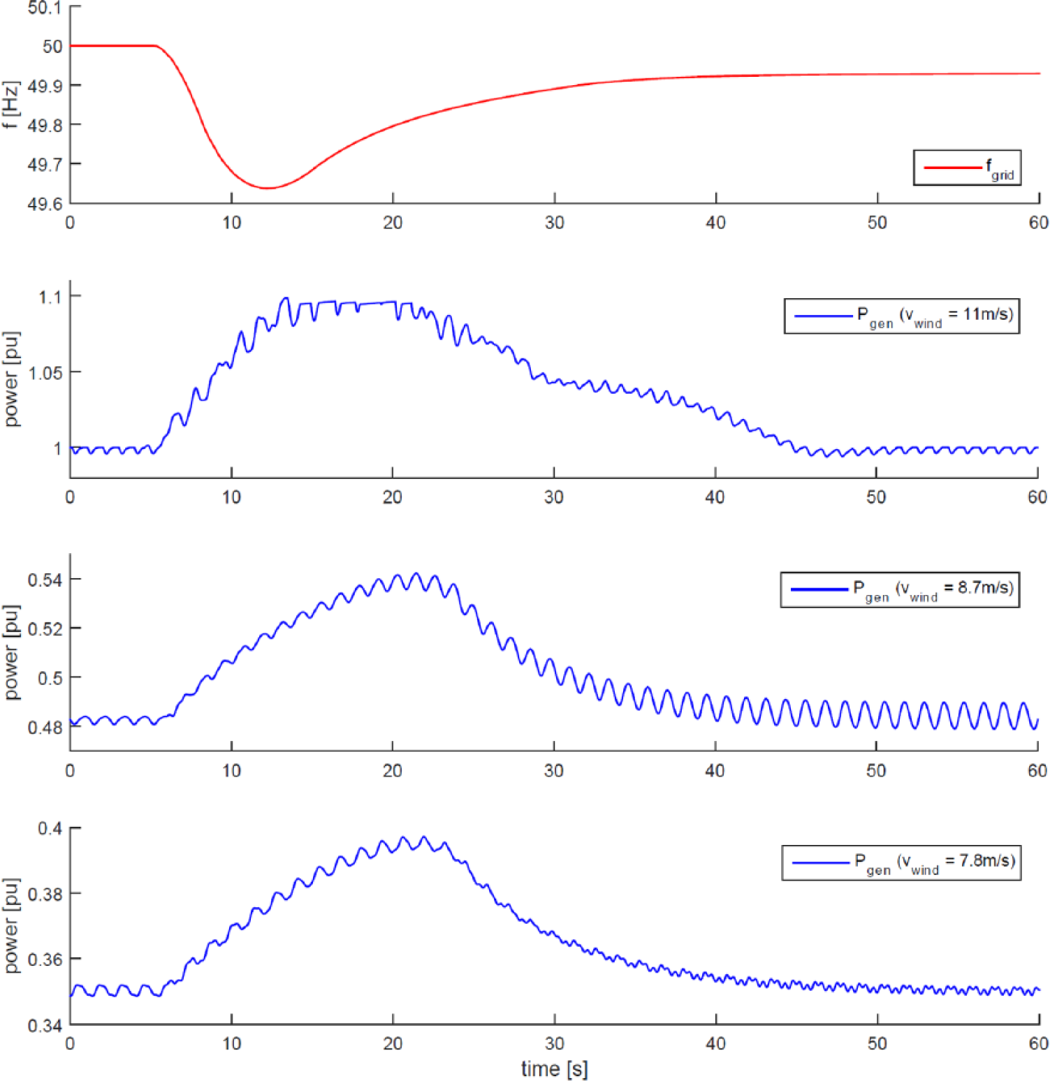
Transient grid frequency dip (top) and the flywheel response for different operating points of the WT.
When the grid frequency underruns, a certain value State V is entered, which means that the flywheel is employed to feed extra power into the grid. This is shown for three different wind speeds in Figure 5. There the stated wind speeds are the averages across the rotor area. The power that is available from the flywheel is obviously dependent on the wind speed, as the considered WT is a variable speed WT; hence, the lower the wind speed, the lower the rotor speed, ωrot. The energy, Ekin, stored in the flywheel is described by equation (19), which reveals that Ekin drops exponentially with ωrot

Figure 5 shows the generator power Pgen, as this yields the most insight into the vibratory behaviour of the drive train. The power in the grid, Pgrid, is smoothened by frequency converter, which can store energy in its direct current (DC) link capacitor. Hence, Pgrid does not exhibit as much variations caused by the vibratory behaviour of the mechanics as Pgen does. The frequency converter is assumed to be lossless.
The behaviour of the flywheel in part-load operating points (vwind = 8.7 and 7.8 m/s in Figure 5) looks similar. The behaviour at 11 m/s looks different, as 11 m/s is almost full-load operation. When the flywheel is discharged in almost full-load operation, Pgen reaches 1 pu. Figure 3 shows that 1 pu cannot be exceeded in normal operation, consequently, the extra power from the flywheel would lead to an acceleration of the rotor beyond ωref. From Figure 1, it can be seen that the speed controller would dissipate the extra power aerodynamically by increasing the pitch angle. In order to assure that the flywheel power can be fed into the grid, in State V the controller switches from ‘LUT Pref = f(ωgen) normal’ to ‘LUT Pref = f(ωgen) grid support’ as in this state the signal ‘grid support’ is high (see Figure 1). The content of ‘LUT Pref = f(ωgen) grid support’ is also shown in Figure 3. Here, it can be seen that when the power versus speed characteristic for grid support operation and the correspondingly higher ωref is chosen, the WT can temporarily increase its power to 1.1 pu. The flywheel controller (block in Figure 1) discharges the flywheel only to the extent necessary for reaching Pgen = 1.1 pu.
In part-load operation (e.g. 8.7 and 7.8 m/s, as shown in Figure 5), Pgen = 1.1 pu cannot be reached. Hence, the flywheel controller discharges the flywheel as quickly as possible, that is, with the maximum flow rate, vfluid_max (Jauch and Hippel, 2015).
Stabilizing power infeed (State IV)
Another way to support the grid is to stabilize the power that the WT feeds into the grid. In previous work, this has been shown for the cases when the flywheel is used for supporting the power infeed when a transient or a permanent drop in wind speed leads to a drop in power (Jauch, 2015; Jauch and Hippel, 2015).
In Figure 6, the averaged wind speed across the rotor plane varies around rated wind speed. The flywheel controller mitigates the power dips caused by the wind. To illustrate the effect in Figure 6, all signals are shown for the case when the flywheel is active (FW ON) and when it is not active (FW OFF). The state of charge of the flywheel is visualized with the radius of the flywheel weight, Rvar, which is the distance of the centre of gravity of the flywheel weight from the centre of rotation (Jauch, 2015).
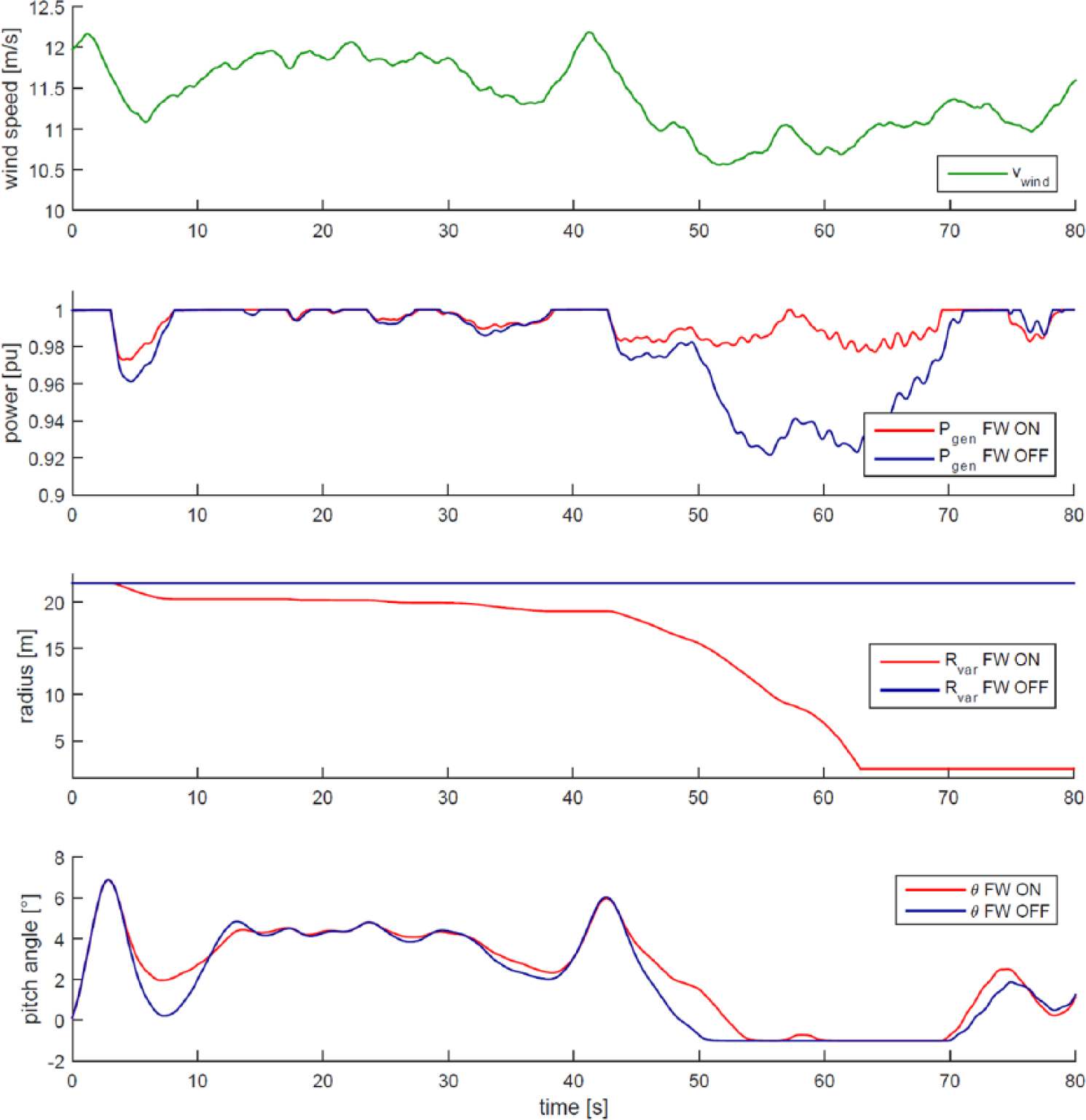
Wind speed varying around rated wind speed. The flywheel stabilizes the power infeed of the WT.
Mechanical load mitigation
Also shown in Figure 6 is how the pitch angle, θ, varies while the WT operates around full load. It can be seen that with the flywheel stabilizing the power, also the pitch angle experiences less variations. The rates with which θ is varied is lower, which means that there is less wear on the pitch system. Since there is generally less variation in operating point, the loading of the WT is more constant, which means lower fatigue loads.
Fatigue loads are mainly caused by mechanical vibrations, where mechanical components vibrate with their eigenfrequency. Figure 7 shows the Campbell diagram of the WT model as illustrated in Figure 2. Due to the flywheel, the eigenfrequency of the blades is obviously not a constant but can vary in a band between the charged state and the discharged state of the flywheel. In the Campbell diagram, the first edgewise and flapwise eigenfrequency are shown for the cases when the flywheel is fully charged and when it is fully discharged. Also shown in the Campbell diagram is the speed range in which the WT can operate in normal operation and for charging the flywheel (Jauch and Hippel, 2015).
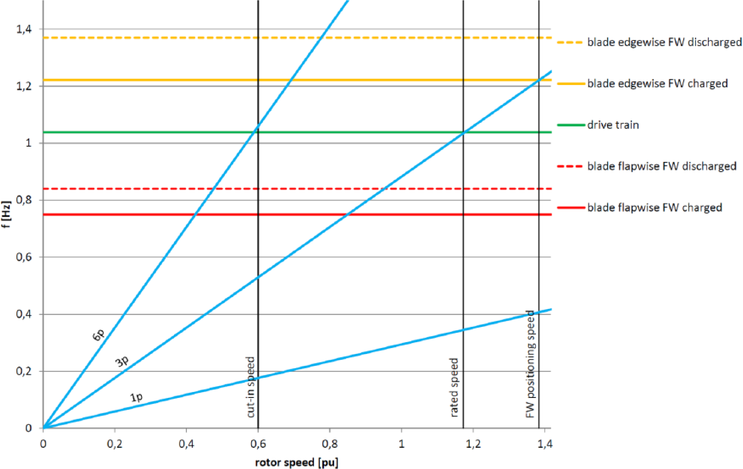
Campbell diagram of WT.
Looking at the excitations 1p, 3p and 6p, it can be seen that 3p can excite the rotor blades in edgewise and flapwise direction and the drive train.
When using the flywheel for mitigating mechanical loads, the goal has to be to avoid intersections between eigenfrequency and excitations and to maintain maximum distance to potential excitations.
Looking at Figure 7, it appears most advantageous to operate with charged flywheel in upper part-load operation, and with discharged flywheel in lower part-load operation. Figure 8 shows a part of the Campbell diagram displayed in Figure 7.
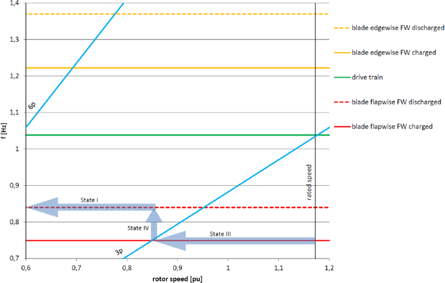
Extract of Campbell diagram shown in Figure 7 and trajectory of states for the case of dropping wind speed.
In Figure 8, the trajectory of the states for a transition from upper part-load operation to lower part-load operation (dropping wind speed) is shown. In upper part-load operation, the flywheel should be charged (State III) in order to have the largest possible distance between excitation (3p) and first blade eigenfrequency flapwise. When the rotor speed approaches the intersection between 3p and this eigenfrequency, State IV is entered assuring maximum distance to the 3p excitation as soon as State I is reached. In order to avoid an intersection between the 3p excitation and the first blade eigenfrequency flapwise in steady-state operation, State IV could already be entered at a rotor speed of about 0.9 pu. This speed is in the middle between the flapwise eigenfrequency with charged and discharged flywheel.
However, intersections between excitations and eigenfrequency do not have to be avoided at any price. When considering the development of mechanical vibrations, the dwell time is of importance. In the operation of WTs, it is virtually impossible to avoid any intersections between excitations and eigenfrequency. But whether or not such excitations lead to vibrations with harmful magnitude, among other factors, depends on the duration of the excitation. In other words, critical excitation is no problem as long as the WT does not dwell on it for too long.
Regarding the vibration with flapwise eigenfrequency of the blade, it has to be noted that vibrations develop quicker with the discharged flywheel, as there the blade has a lower inertia. Hence, the trajectory shown in Figure 8 suggests to approach an intersection of 3p excitation when the flywheel is charged (State III = high inertia) and then cross over (State IV) to maintain maximum distance to 3p when the flywheel is discharged (State I = low inertia). This is illustrated with the simulations shown in Figures 9 and 10.
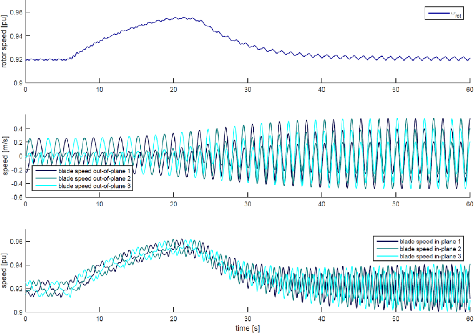
Discharging of the flywheel at a wind speed of 8.7 m/s.
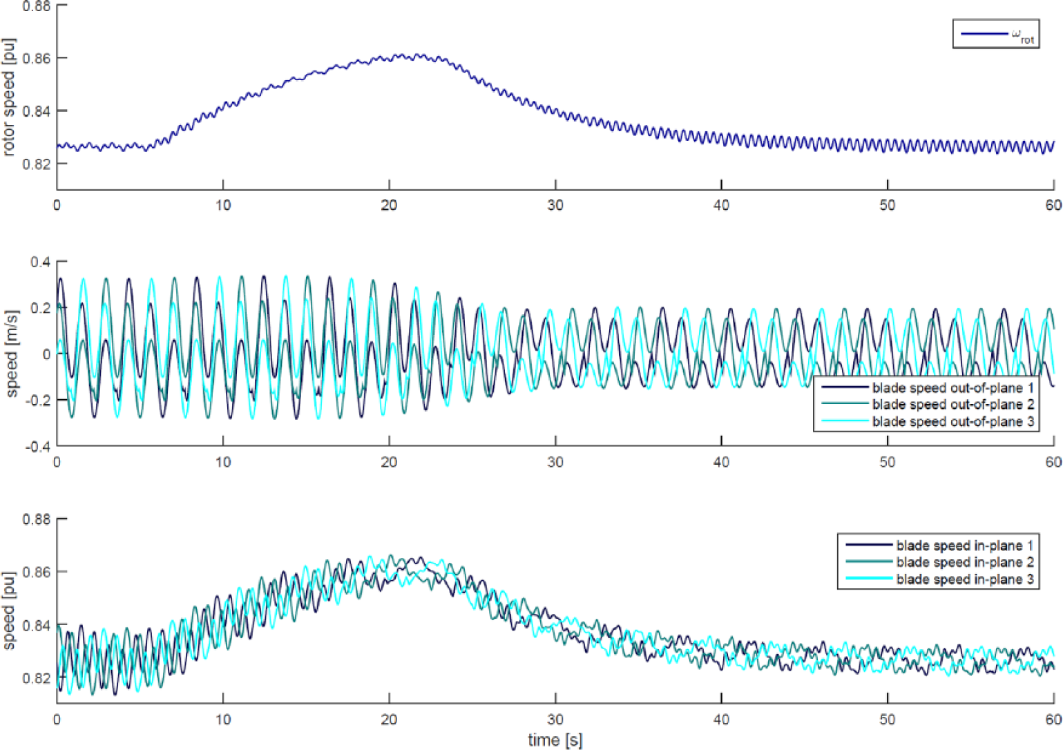
Discharging of the flywheel at a wind speed of 7.8 m/s.
Figure 9 shows the situation where the WT operates at a wind speed of 8.7 m/s averaged across the rotor plane. The blades vibrate in edgewise and flapwise direction. In Figure 9, this is visualized as in-plane and out-of-plane vibrations, which in part-load operation (θ ≈ 0°) is approximately the same as edgewise and flapwise, respectively. The flywheel gets discharged with the effect that the blade vibrations increase considerably. Looking at Figure 8, it becomes obvious that discharging the flywheel at a rotor speed of around 0.92 pu moves the blade eigenfrequency flapwise close to the 3p excitation. Hence, the increase in magnitude flapwise is as expected. Figure 9 reveals that also the magnitudes of the edgewise vibrations increase. The aerodynamics provides a link between flapwise and edgewise motion as the experienced wind speed is offset by the blade motion (see equation (15)).
Figure 10 shows a discharging of the flywheel at 7.8 m/s. Here, the vibrations in the blades decrease as the blade eigenfrequency flapwise is moved away from the 3p excitation. Again, this also has an effect on the blade vibration edgewise.
When the flywheel is discharged in order to mitigate mechanical vibrations, it is obviously no longer available for grid frequency support should there be a contingency in the grid. This, however, is only a minor problem. Since the energy stored in the flywheel is a function of the square of the rotational speed, in lower part-load operation the contribution to grid frequency stabilization is anyway diminished (see equation (19)).
Looking at Figure 7, also other intersections between excitations and eigenfrequency can be observed. There is one intersection of 3p with the blade eigenfrequency edgewise when the flywheel is charged. This excitation is not critical though, as the WT dwells on the rotor speed for positioning the flywheel weight only until the flywheel is fully charged, which lasts for 20 s. Once the flywheel is charged, that is, once this eigenfrequency has arrived at the excitation frequency of 3p, the WT leaves this operating point immediately.
Also, there are intersections between the 6p excitation and the first blade eigenfrequency edgewise. As can be seen in Figure 8, the blade is bound to experience excitations in edgewise direction at a rotor speed of about 0.78 pu. This is accepted though, as 6p excitations contain less energy than 3p excitations. Also, the slope of the 6p excitation is steeper, which means that it is less likely that the WT operates at a speed of exactly 0.78 pu for a longer time.
When the WT operates in lower part-load operation and the wind speed rises, the flywheel has to get charged (State II) to mitigate mechanical vibrations in upper part-load operation. Also, when the flywheel was discharged in upper part-load operation due to a drop in grid frequency, it has to get charged again as soon as possible.
Since the rotor blades are the most vibratory components in a WT, it is obvious to use the flywheel system to minimize fatigue loads in the rotor blades. However, the flywheel could also be applied to detune the eigenfrequency of other vibratory components in the WT.
Conclusion and future work
The system of a flywheel in a WT rotor has been proposed in previous publications. In the past, the sole purpose of this system was to provide the grid with extra power in order to stabilize the grid frequency transiently. Since such a flywheel varies its inertia, it also varies the inertia of the rotor blades in which it is located. Hence, it directly impacts on the vibratory behaviour of the blades. Therefore, in this article a control strategy is proposed that utilizes this effect in order to mitigate mechanical vibrations and by doing so minimize mechanical loads.
The proposed control strategy serves both purposes: grid frequency support and mechanical load mitigation. The simulations show the performance of the system.
As already introduced in section ‘Preparation of flywheel’, there are different methods of charging the system conceivable. Charging can be done with centrifugal forces only, with a combination of centrifugal forces and actuator forces, or with an electrically driven actuator only. This constitutes a difference in the complexity of the system and in the required rotor speed for positioning the flywheel weights. Currently, the system is designed as simple as possible, that is, without any auxiliary drives. Hence, positioning the flywheel weights is done with centrifugal forces only. In future, it will have to be analysed whether a system with an electrically driven weight positioning actuator would be advantageous. Provided that such a drive is dimensioned sufficiently, this would allow charging the flywheel at rated rotor speed. When the wind speed suffices for at least rated power infeed in the grid, the generator could be overloaded temporarily to also generate the electric power needed for positioning the flywheel weights. This would reduce the common problem of negative damping in full-load operation, where the electric power fed into the grid is kept constant at speeds beyond rated speed (see Figure 3), that is, dropping torque at rising generator speed.
Another topic that has to be investigated in future is how a flywheel system on the high-speed shaft of a conventional WT drive train could be applied to detune the eigenfrequency in different WT components. The immediate advantage of such a system is that it has much smaller dimensions due to the much higher rotational speed. The downside is that the possible impact on the flexible rotor blades is reduced drastically.
Footnotes
Appendix 1
Simulation model parameters.
| Parameter | Value | Unit | Comments |
|---|---|---|---|
| Rated power of WT (power base) | 2 | MW | Corresponds to Pgen = 1 pu |
| Rrot | 40 | m | Radius of WT rotor |
| Speed base | 1500 | r/min | Synchronous speed of generator, high-speed side of gearbox, corresponds to ωgen = 1 pu |
| Gearbox ratio | 85 | – | |
| ωref | 1.1724 or 1.2109 or 1.3524 | pu | 1.1724 for normal operation, 1.2109 for grid support operation and 1.3524 for positioning the flywheel weight |
| Jhub | 0.0154 | pu | Low-speed side of gearbox |
| Jhss | 150 | kg m2 | High-speed side of gearbox |
| Kstiff | 79.2 | pu | High-speed side of gearbox |
| cdamp | 0.5629 | pu | High-speed side of gearbox |
| Jbladeroot | 6.8311E+05 | kg m2 | |
| Jbladetip | 9.422E+05 | kg m2 | |
| Ks_blade_flap | 26,250,762 | N m/rad | |
| Ks_blade_edge | 69,827,175 | N m/rad | |
| cd_blade_edge | 100,000 | N s/m | |
| cd_blade_flap | 1,500,000 | N s/m | |
| mbladetip | 1022 | kg | Mass of tip section of blade |
| Rbladetip | 30 | m | Distance of tip section of blade from rotor centre |
| mfw | 500 | kg | |
| vfluid_max | 6 | m/s | Maximum flow rate of hydraulic fluid in flywheel |
| KP_FW | 250 | m/s/pu | Proportional gain of flywheel controller |
| KI_FW | 30 | m/s/pu | Integral gain of flywheel controller |
| g | 9.81 | m/s2 | Gravitational acceleration |
WT: wind turbine.
Declaration of conflicting interests
The author(s) declared no potential conflicts of interest with respect to the research, authorship and/or publication of this article.
Funding
The author(s) received no financial support for the research, authorship and/or publication of this article.