
Abstract
Ensuring the structural integrity of wind turbine blades under extreme wind loading remains a critical challenge in wind engineering. This study introduces a novel passive load mitigation approach through the integration of an internal beam/cable support system within the blade architecture. The proposed system is designed to offload and redistribute stress away from the primary fiber-reinforced composite structure, thereby enhancing load-bearing capacity without significantly increasing structural weight. Numerical analyses were performed using ANSYS ACP (Pre) and ANSYS Mechanical (2023 R2), assessing various fiber layup configurations subjected to simulated extreme wind conditions. Key structural performance metrics including blade deflection, stress distribution, and failure risk (evaluated via inverse reserve factors) were examined. The findings indicate that the support system effectively limits blade deflection within conservative design thresholds across different layup thicknesses. Additionally, notable reductions in stress concentrations were observed, accompanied by substantial improvements in failure resistance. These results underscore the system’s potential to enhance blade reliability under critical loading scenarios. This work presents a structurally efficient and practically implementable strategy for improving the resilience of composite wind turbine blades. The approach holds strong promises for advancing cost-effective, durable solutions in modern wind turbine design, particularly in environments characterized by severe wind events.
Keywords
Introduction
Within wind turbine structures, the blade plays a crucial role as the primary component responsible for converting wind energy into mechanical energy in the form of rotating inertia. Although the wind propels the blades to motion, wind gusts pose a significant threat to wind turbine integrity (Portal Energia, 2014; Shohag et al., 2017). A study investigating wind turbine failures identified heavy rainfall and strong winds as the most prevalent causes, accounting for 43.59% of total failure causes (Chou et al., 2013). Notably, blade damage emerges as the most common and costly type of damage, requiring substantial time for repair (Chou et al., 2013; Ciang et al., 2008; Larsen and Sorensen, 2003; Shohag et al., 2017; Ye et al., 2019). Blades contribute significantly to the overall turbine cost, accounting for 15%–20% of the total expense (Ireland, 2011). Most of the blade damage occurs at the blade root surface, progressing along the span wise direction. Specifically, the regions more susceptible to damage are the first 30%–35% and the last 70% of blade length along the axial locations (Ciang et al., 2008; Shokrieh and Rafiee, 2006; Sundaresan et al., 2002). Due to the challenge of inspecting wind turbine blades for early damage prevention, devising a safe-life design approach is recommended to ensure the wind turbines withstand extreme conditions for 20 years or more during their operational lifespan (Harper and Hallett, 2015; Hayman, 2007; Nilsson and Bertling, 2007).
The utilization of lightweight materials and the increase in size contribute to the enhanced flexibility of wind turbine blades, concurrently resulting in higher structural loads (Do et al., 2020). Moreover, the occurrence of unexpected direction changes in wind gusts can impose significant aerodynamic loads on wind turbine blades. These loads have the potential to induce fatigue, trigger automatic shutdowns, or even lead to damage in specific turbine components (Shohag et al., 2017). Considering the impact of loading on wind turbines, studies indicate that gravity loading induces edgewise bending, while flap-wise bending occurs under maximum gust loading conditions, particularly when the wind direction is perpendicular to the blade planform (Barnes et al., 2015). According to an assessment by Barnes et al. (2015), the most substantial loads that a wind turbine experience are aerodynamic loads. During operation under gust and rated wind speeds, the aerodynamic force components act in different directions, with the lift force acting in the flap-wise direction and the drag force in the edgewise direction (Barnes et al., 2015).
Among the various load cases specified by IEC 61400-2, (2005) for the design of small wind turbines, load case “A” (fatigue analysis) and load case “H” (extreme wind conditions under parked and operating conditions) have been the subject of extensive study in the literature (IEC 61400-2, 2005; Forcier et al., 2013; Park, 2016; Choi et al., 2020; Tenghiri et al., 2021). Load case “H” is identified as the critical scenario, significantly influencing flap-wise bending of the turbine blades (Forcier et al., 2013; Tenghiri et al., 2021). A maximum root bending moment is reported when the wind turbine, during normal operation, encounters extreme operating gusts (Forcier et al., 2013). Additionally, another extreme load case is presented by wind gusts at operating wind speeds with variations in wind direction (Park, 2016). Furthermore, the operational environment of small wind turbines is often characterized by high turbulent flow areas due to limitations in operating height and other factors. These conditions result in higher loading on the blades due to elevated gyroscopic loading during yawing (Wilson et al., 2008). Studies focusing on the impact of gyroscopic loads reveal that they are among the largest contributors to stress on the main shaft of the turbine (Da Costa and Clausen, 2020).
Moreover, qualitative comparisons of structural design between high wind speed and low wind speed turbines are detailed in Griffin and Ashwill (2003), highlighting blade stiffness and associated tip deflections as critical conditions. Similarly, investigations into the design of low wind speed turbines emphasize the prominence tip deflection, particularly under maximum gust load situations (Barnes et al., 2015). It also revealed that deflection in low wind speed blades is substantial enough to impact aerodynamic performance by diminishing the effective swept area during rated wind speed loading. Consequently, addressing these challenges, the authors recommended the adoption of a design process driven by increased stiffness to enhance structurally efficient blades operating at low wind speeds (Barnes et al., 2015).
Numerous studies have focused on mitigating induced loads that affect the structural efficiency of wind turbines. Among these, active control strategies—particularly individual and collective pitch control—are the most explored and extensively studied (Badihi et al., 2021; Sinner and Pao, 2018; Truong et al., 2022; Xie et al., 2023). In individual pitch control (IPC), each blade is adjusted independently using individual pitch angles, allowing for targeted load reduction. In contrast, collective pitch control (CPC) adjusts all blades simultaneously using a uniform pitch angle, primarily to regulate power output near the rated value (Badihi et al., 2021; Sinner and Pao, 2018; Xie et al., 2023). IPC is widely adopted for structural load mitigation, while CPC serves as a primary mechanism for maintaining consistent energy production. Furthermore, active structural control research frequently explores the implementation of tuned mass damper system, which is commonly employed to suppress vibrations induced in wind turbine structures (Truong et al., 2022).
A comprehensive review and assessment on active control methodologies were also conducted by Truong et al. (2022), with a primary focus on system stability and reliability. The evaluation of blade pitch control strategies revealed that inappropriate control commands could induce vibrations in both edgewise and flap-wise vibrations of the blade as well as tower motions. Consequently, the influence of blade pitch control on tower and blade vibrations necessitates the consideration of additional stabilizing control strategies when implementing different control methods in wind turbines (Truong et al., 2022). Additionally, it was reported that the application of individual or collective pitching of the blades, commonly used to reduce bending in both blades and towers, may impact the power production performance of wind turbines (Do et al., 2020). This underscores the need for alternative methods capable of minimizing or mitigating these effects. Furthermore, the requirement of extensive knowledge of the dynamics and structural analysis of wind turbines when employing control strategies is acknowledged as a potential drawback (Truong et al., 2022).
Another load mitigation method discussed in the literature is passive aero-elastic coupling, aiming to mitigate loads by inducing bend-twist coupling in the blades. This approach involves introducing deformation to the structure under increased loading, counteracting the increased loading itself (Bortolotti et al., 2019; Sun et al., 2023). The bend twist coupling induces a change in the angle of attack, leading to blade stall or feather (Bortolotti et al., 2019). Additionally, various studies have presented active and passive stall regulation techniques applicable to small wind turbines (Barzegar-Kalashani et al., 2023; Jauch et al., 2004; Labuschagne and Kamper, 2022; Sareni et al., 2009; Song et al., 2022). These techniques are categorized as active stalling, where an electromechanical-driven pitching system is required, and passive stalling, where blade pitching is achieved by regulating the generator’s power and torque through modifications to the power converters’ controller. However, the implementation of such load mitigation techniques involves complex and costly electromechanical architecture, promoting the need for alternative approaches (Barzegar-Kalashani et al., 2023; Labuschagne and Kamper, 2022; Song et al., 2022).
An alternative load mitigation technique is introduced by Castillo et al., 2021, featuring a flexible wind turbine employing a cam mechanism to modify the outer profile of the blade. Similar studies explore the utilization of deformable rotors with blade flap configurations to mitigate load effects in wind turbine blades (Bernhammer et al., 2016; Jauregui et al., 2021; Oltmann et al., 2017; Sun et al., 2017). Assessments of load alleviation potential using controllable rubber trailing flaps reveal a substantial reduction in lifetime fatigue loads for certain load channels, particularly in flap-wise root moments. However, this reduction is achieved at the cost of high actuators activity, and there is a potential decrease in some extreme loads, whether using the flap alone or in combination with individual pitch control (Barlas et al., 2015). Furthermore, it is noted that the impact on extreme loads is highly sensitive to specific controller parameters in fault cases. The study suggests the need for further exploration of improved methods for handling extreme load cases, specifically in parked and fault scenarios (Barlas et al., 2015).
The predominant fiber composites used in wind turbine blades are glass and carbon fibers. E-glass fibers serve as the primary reinforcement, constituting up to 75% by weight in typical glass/epoxy composites for wind blades (Mishnaevsky and Brøndsted, 2009; Mishnaevsky et al., 2017). These composites, predominantly E-glass/epoxy, are employed to ensure the blades endure the various loading encountered throughout their operational lifespan, satisfactorily meeting most loading conditions but necessitating alternative solutions for extreme loading conditions (Mishnaevsky et al., 2017). Carbon fibers, as an alternative, offer significantly higher stiffness and lower density compared to glass fibers, enabling the use of thinner, stiffer, and lighter blades. However, carbon fibers exhibit lower damage tolerance, increased sensitivity to fiber misalignment and waviness, lower compressive strength, ultimate strain, and are notably more expensive than the E-glass fibers (Grande, 2008; Mishnaevsky et al., 2017). To strike a balance between enhanced performance and cost considerations, a combined use of carbon fibers and E-glass fibers is explored, providing higher stiffness with a limited increase in cost (Mishnaevsky et al., 2017).
In response to the ongoing demand for effective load mitigation and cost reduction in wind energy production—particularly under extreme wind conditions impacting both large-scale and small-capacity turbines—numerous strategies have been proposed, including active pitch control, tuned mass dampers, aero-elastic coupling, and smart material configurations. While active strategies like individual and collective pitch control offer dynamic adaptability, they often introduce complexity, cost, and reliability challenges, including sensitivity to control errors that can induce additional structural vibrations. Passive methods such as bend-twist coupling and deformable blade concepts reduce reliance on external controls but can be limited in responsiveness and scalability. Similarly, advanced material solutions like hybrid carbon-glass fiber composites improve stiffness-to-weight ratios but increase cost and introduce manufacturing constraints.
This study presents a novel passive load mitigation alternative: a passive beam/cable support system integrated within the blade structure. Unlike existing active or material-based methods, this system offers a mechanically simple and structurally robust solution that offloads extreme wind-induced loads from the primary fiber structures, enhancing performance without compromising design flexibility. Although cable-supported systems are well established in civil engineering—especially in long-span bridge structures and construction cranes exposed to high wind forces (Gimsing and Georgakis, 2012; Podolny and Scalzi, 1986)—their application in wind turbine blades remains largely unexplored. Drawing from these proven load-resilient systems, this research introduces a new structural paradigm aimed at enhancing the fatigue life, stiffness, and safety margins of wind turbine blades under extreme load scenarios. The proposed solution not only addresses the shortcomings of current mitigation strategies but also offers a cost-effective and scalable approach suitable for next-generation turbine design.
Initially, the blade design adopts a shell structure with fiber composites, implemented using ANSYS ACP (Pre) (version 2023 R2) (ANSYS Inc., 2023). Subsequently, a load-alleviating supporting beam/cable support system, coupled with lightweight structures, is implemented as a solid beam structure in ANSYS Mechanical (version 2023 R2). This system is then combined with the shell structure as beam elements within ANSYS Static Structure (version 2023 R2). The analysis includes an assessment of maximum deflection, stresses, and failure criteria based on inverse reserve factors of the composite blade. Through this comprehensive assessment, the study presents the extreme load mitigation capabilities and comparative advantages of the proposed methodology.
Materials and methods
Modern wind turbine blades predominantly employ glass fiber-reinforced plastic (GFRP) structures, incorporating sandwich panels for trailing edge sections and shear webs, while spar cups are predominately made of unidirectional GFRP to withstand large flap-wise bending loads (Barnes et al., 2015). The potential advantage of carbon fibers, characterized by higher stiffness and lower density, could address challenges related to failures resulting from extreme wind loads, provided effective measures are implemented to overcome inherent drawbacks.
The paper focuses on the analysis of a 5-kW wind turbine blade. The aerodynamic design of the blade presented in Kelele et al. (2022) serves as the basis for structural analysis outlined in this paper, assuming the aerodynamic design of this blade would be implemented at sites with different wind conditions of low to high class. The arrangement of shear webs is coordinated with the shell, as depicted in Figure 1. This arrangement is utilized in structural analysis, with fiber layout considerations incorporating integrated shell and spar cups, while the shear webs are treated following the layout shown in Figure 1. Shear webs arrangement relative to the shell of the blade.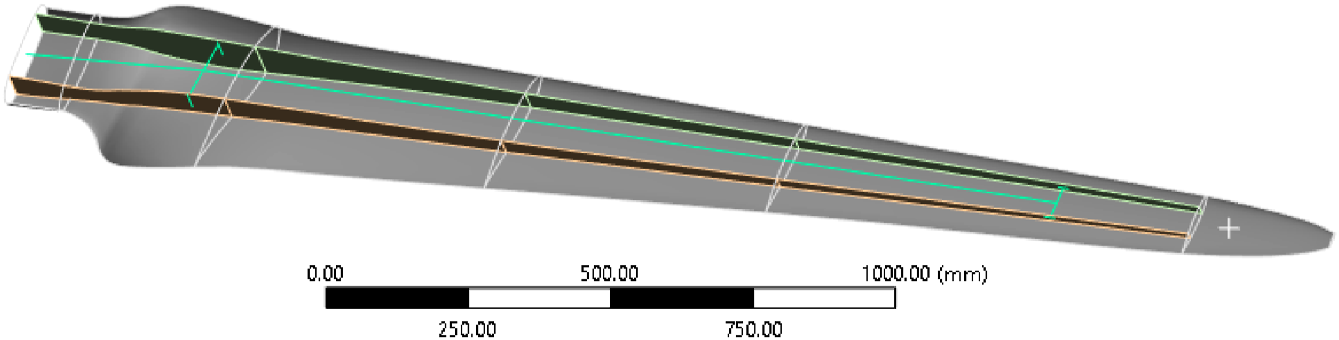
The upper and lower skins of wind blade primarily endure shear, flexure, and torsion loads, with angle plies oriented at ±45° to accommodate these forces. In contrast, the spar flanges are designed to handle bending loads and are reinforced with plies oriented at 0°/90° (Park, 2016). The fiber layups and orientation angles used in the analysis are based on Epoxy Carbon Woven Prepreg materials, selected from the ANSYS material library. The material properties include a longitudinal and transvers modulus (E1, E2) of 61.34 GPa, a perpendicular modulus (E3) of 6.9 GPa, shear modulus (G12) of 3.3 GPa and (G13, G23) of 2.7 GPa, Poisson’s ratios (ν12, ν23) of 0.3, and density of 1420 kg/m3.
To illustrate the proposed method, the shell and spar-cup are integrated, with the woven carbon fiber (WCF) layup at +45°/−45° for the shell’s top surface, expected to endure shear and flexural loads. Spar-cup layers are arranged with plies of 0°/90° angle woven carbon fibers, carrying bending force mainly in the blade flap-wise direction. Shear webs use +45°/−45° angle plies of woven carbon fibers, on one side, honeycomb core material at the middle, and another +45°/−45° angle plies of woven carbon fibers at the other side. Various thickness values of woven carbon fiber (0.2 mm–0.6 mm) are considered to demonstrate different parameters for blades with and without the beam/cable support system, while a core thickness of 2.0 mm is used for all cases in the shear-webs.
Furthermore, it is essential to pay close attention to the ply layout, as it constitutes an integral aspect of wind turbine composite analysis. In this study, common arrangements supporting intended loads under different conditions are applied using ANSYS ACP (Pre) (version 2023 R2), a composite module facilitating fiber arrangement and analysis (Tsai and Wu, 1971). ACP (Pre) in ANSYS employs a ply-wise approach creating the entire laminate ply by ply.
Moreover, this study proposes the integration of a beam/cable support system, consisting of a 3 mm diameter aluminum alloy rod or steel cable, within shear webs of the blade structure, as depicted in Figure 2. Placing the support system inside the turbine structure aims to prevent interference with the aerodynamic air flow on the outer surface. The beam/cable is supported by 2 mm thick square section cross beams positioned at approximately 14% and 79% of the blade span. In cases involving two-beam/cable support system, the second supporting cross beam is centrally located along the blade span. Front connections are strategically situated at the midpoint of the shear web’s height and assumed firmly fixed to the shear web walls using 2 mm thick aluminum alloy plates. Rear attachments are located at the upper extent of the shear web height to ensure that the stretched rod or cable applies forces against bending deflection. Shear webs with beam/cable supporting system.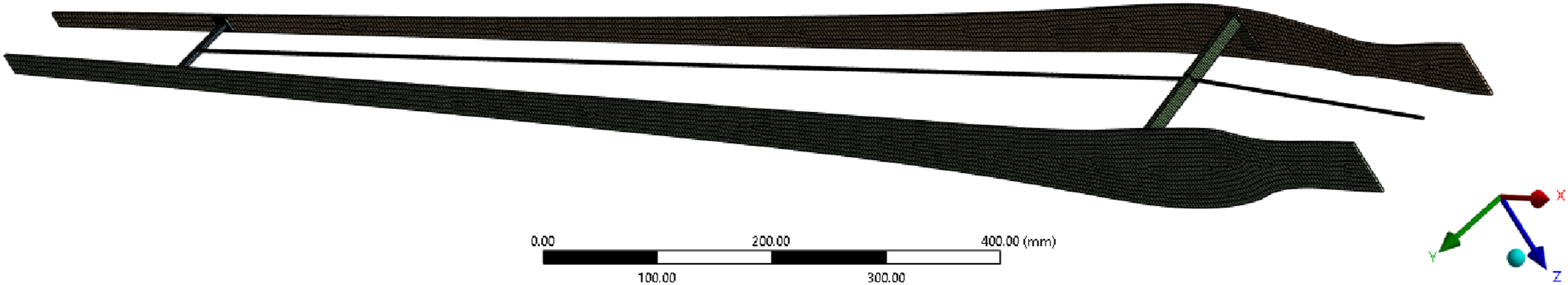
The beam/cable support system is expected to redirect and distribute some of the loads away from the blade fiber structures, assuming the end point of the proposed beam/cable system be attached to other parts of the turbine, like the hub. This could be implemented in ANSYS with the application of remote point and/or fixed-point application.
Subsequently, the blade shell and structure undergo analysis using the Static Structure module of ANSYS Mechanical (version 2023 R2). Inertial loads due to motion could be implemented by applying the rotational speed of the rotor, and gravitational loads are automatically considered by the software. Aerodynamic and extreme wind loads would be applied as pressure loads on the blade surface. The load case “H,” defined in IEC 61400-2 (IEC 61400-2, 2005), is chosen analysis, representing the extreme condition for wind turbine blades based on a 50-year extreme wind value for class I wind conditions. In designing the structure of the blade, the assumption of wind condition for class I small wind turbine would accommodate the other defined classes. According to the basic parameters table for small wind turbine class I of IEC 61400-2, average wind speed
For parked turbines, the blade root bending moment in the out-of-plane direction is dominated by drag (IEC 61400-2, 2005). The load due to extreme wind for parked wind turbine condition is implemented using wind pressure on faces of the blade defined, based on the representation for moment in IEC 61400-2 (2005) as follows:

Similarly, for rotating turbines at

The load conditions for extreme wind speed are defined by equations (1) and (2), where

For comparison, the critical condition is utilized in the analysis. As per the IEC 61400-2 standard, full characterization and ultimate load calculations consider a material partial safety factor

As highlighted in the introduction, under extreme load conditions, tip deflection emerges as a more dominant factor for low wind speed blade designs (Sun et al., 2017). Based on the adaptation of classical Euler–Bernoulli beam theory using an effective flexural modulus

To minimize
This study adopts the later approach, by introducing an internal beam/cable supporting system integrated with blade’s shear webs, as shown in Figures 1 and 2. In wind turbine design, tip deflection of cantilevered blades is typically limited to a small fraction of the rotor radius—typically around 10−15% as per common industry practice— to ensure structural integrity and prevent blade-tower interaction. The allowable deflection depends on factors such as turbine class, blade geometry, and control strategies.
The blade, with and without the integrated beam/cable support system, was modeled as a cantilever beam and analyzed under static loading conditions representative of Load Case H, as defined in IEC 61400-2. This case simulates extreme wind loads under parked turbine conditions, where the rotor is not actively controlled and subjected to a 50-year wind gust event. To replicate the fixed hub connection, the blade root and the terminal point of the support system were fully constrained in all degrees of freedom. Aerodynamic pressure loads, derived from the reference wind speed for Class I small wind turbines, were applied along the blade span in the flap-wise direction, simulating the pressure distribution typically observed during extreme gusts. This setup enables a direct comparison of structural response with and without the internal support system under identical extreme conditions.
To ensure the immediate activation of the support system during blade deflection, a small remote force of approximately 10 N was applied to the beam/cable within the ANSYS Static Structure module (version 2023 R2). The same composite layups, fiber orientations, boundary conditions, and load cases were maintained across both configurations for consistency and accurate comparison. Figure 3 shows the applied boundary conditions and loading setup, based on the extreme wind scenario and the relationships defined in equations (1) through (3). Boundary conditions applied on the blade surface and cable/beam support.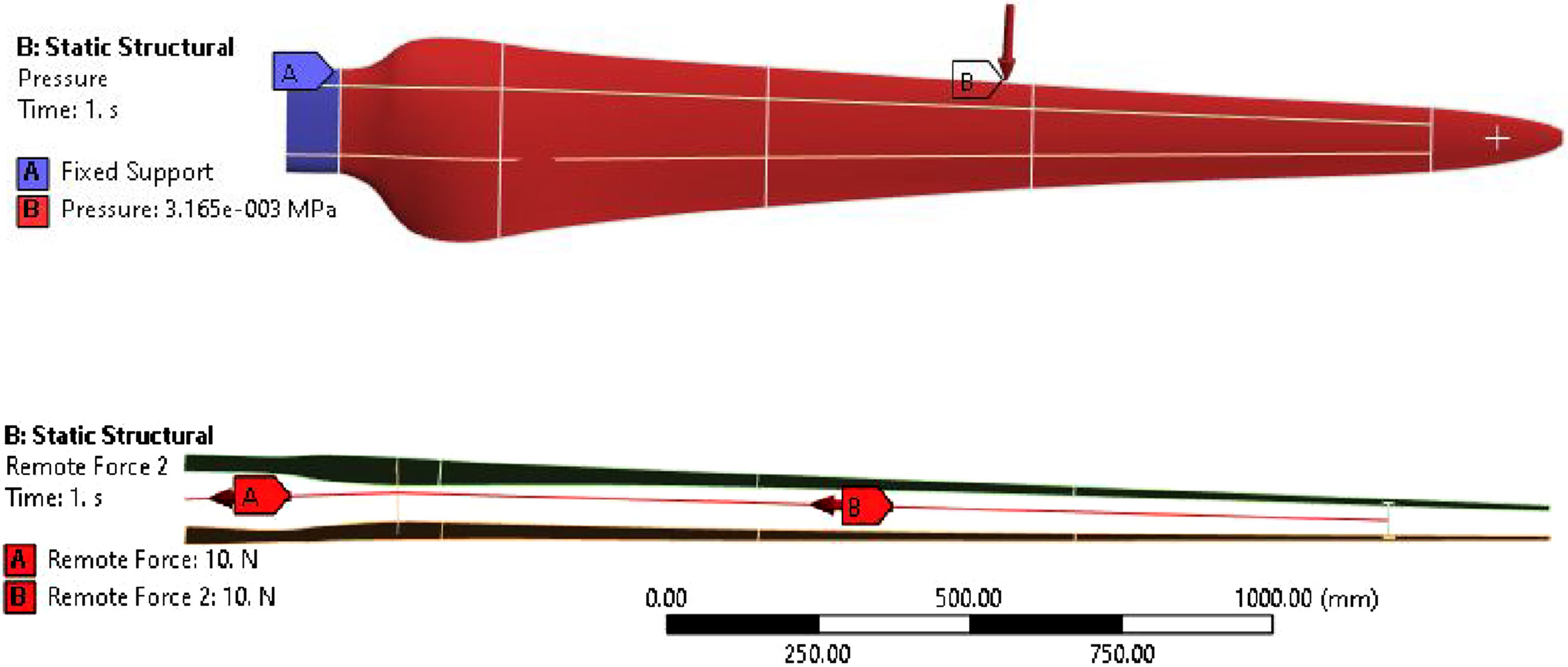
Finally, results of total deformation and equivalent or von Mises stresses are determined for both cases using ANSYS Static Structure (version 2023 R2) (ANSYS Inc., 2023). Moreover, failure analysis based on Inverse Reserve Factor (IRF) criteria, considering Tsai-Wu, maximum stress, and maximum strain methods, is applied to determine the failure conditions of the composite structure of the blade with and without support system. These include fiber failure, matrix failure, in-plane and out-of-plane shear failure, and delamination. In this paper, IRF, which is the inverse of the reserve factor, is used as failure criteria. According to most of the literature studies, IRF is defined generally as the ratio of ultimate load to ultimate strength, where an IRF value greater than one indicates failure and less than one represents a safe condition. Tsai-Wu failure criteria are spectacular material failure criteria which are commonly used for composite materials failure analysis in most commercial software (Tsai and Wu, 1971).
Since ANSYS is finite element software, ensuring mesh quality is essential for achieving accurate results. A structured meshing approach was adopted to enhance the precision of stress and deflection analysis. Both global and local mesh controls were applied, with a minimum element size of 1 mm specified for the cable support system. Adaptive sizing and mesh de-featuring were employed, maintaining a growth rate below 1.2 to ensure mesh refinement. To verify mesh independence, convergence studies were conducted. The resulting finite element mesh demonstrated high quality, with element quality values typically exceeding 0.8 and averaging around 0.96. Skewness values kept below 0.2, with an average of 0.047. The aspect ratio was also well-controlled, with a maximum of about 3 and an average of roughly 1.04.
Different cases based on various thickness values of the woven carbon fiber are considered keeping the arrangements and layups as described above for both conditions and the results of the deformation, stress, and the IRF compared. Finally, improvements provided with the suggested method of load mitigation are presented, comparing the results for both cases at different thicknesses of the utilized composite fiber.
Results and discussion
To facilitate a comprehensive comparison between the blades with and without the beam/cable support system and clarify the comparative advantages, the evaluation will initially focus on the blade without any support system. For this analysis, a woven carbon fiber layup configuration was employed in ANSYS ACP (Pre) (version 2023 R2) for integrated shell and spar-cup, consisting of one layer at +45°/−45° on the outer position, one layer at 0°/90° at the middle position, and one layer at +45°/−45° in the inner position. Similarly, the shear-webs layup comprises WCF with one layer at +45°/−45° on one side, a 2 mm thick core at the middle, and one layup of +45°/−45° on the other side. The blade without the support system was analyzed using WCF layups set at thickness of 0.6 mm, resulting in a total thickness of 1.8 mm for the integrated shell and spar-cups and 3.2 mm for the shear-webs, including the 2 mm honeycomb core.
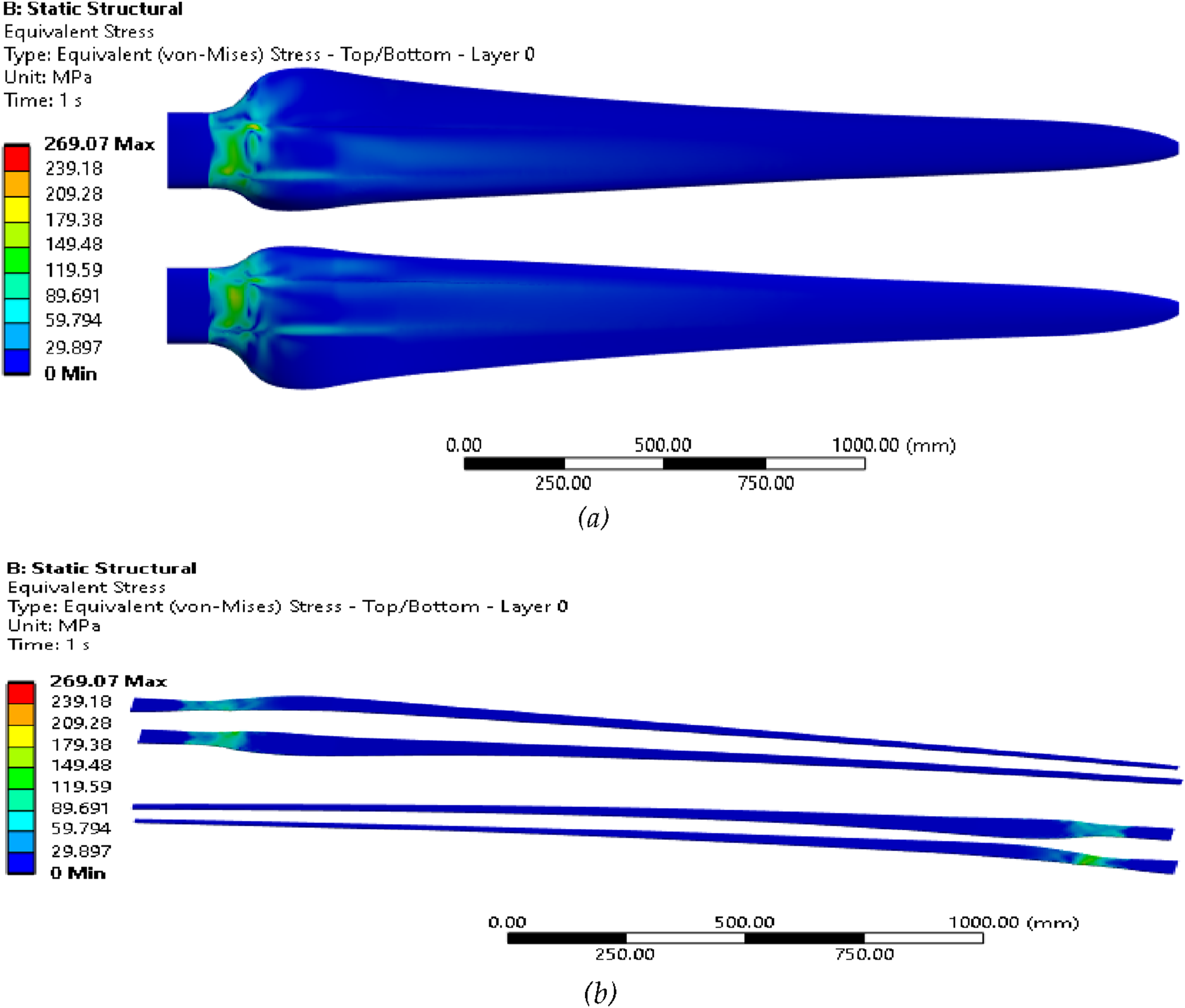
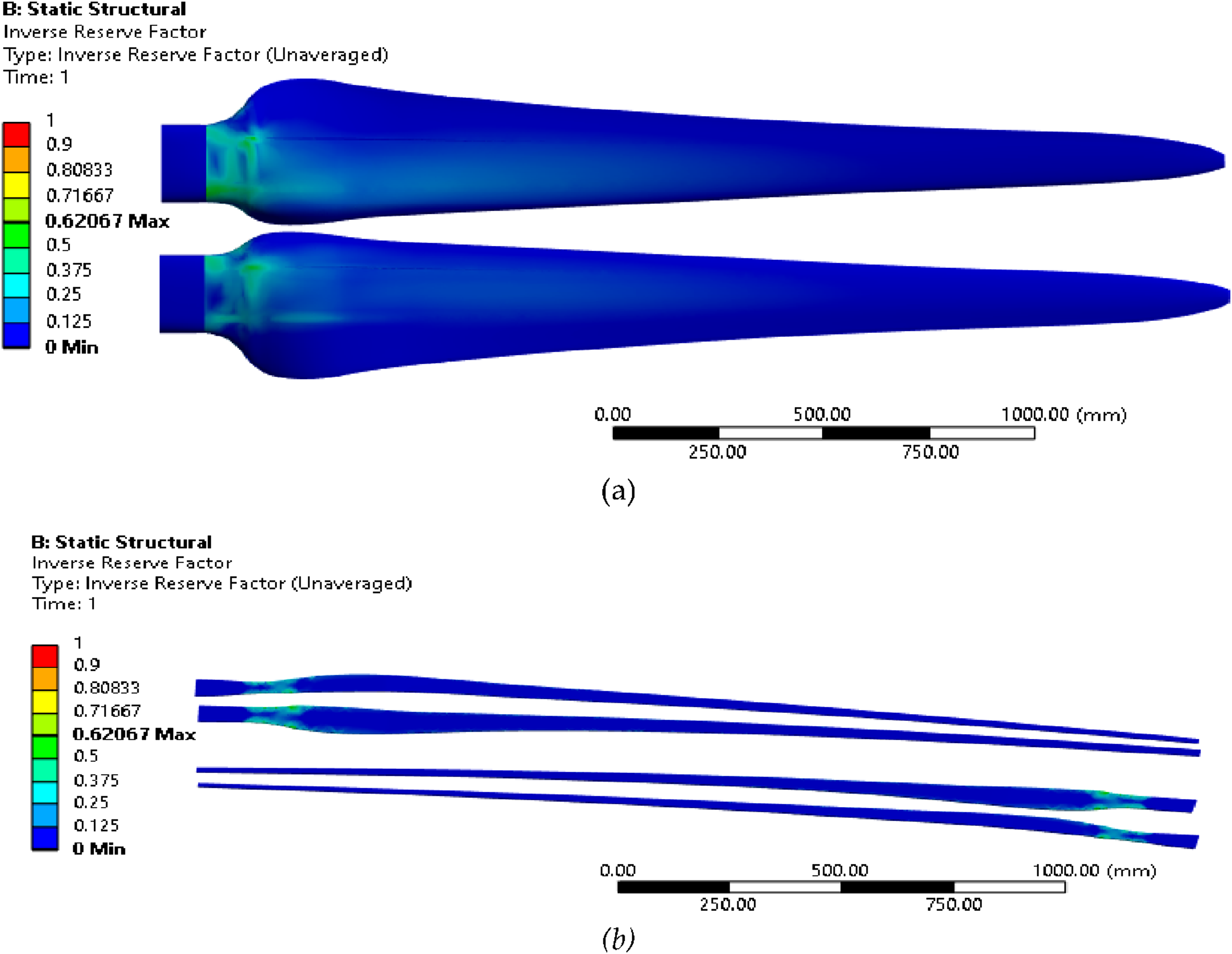
The results indicate that the blade deflection relative to the un-deformed model is depicted in Figure 4. With a blade length of 2.5 m, the maximum deflection is recorded at 146.4 mm, significantly less than 20% of its length, thereby adhering to basic engineering principles. Concurrently, the equivalent stress is represented in Figure 5. Figure 5(a) illustrates the equivalent stress for the shell and spar cup, while Figure 5(b) depicts the stress distribution for the shear webs. The maximum stress recorded is 269.1 MPa, and it is crucial to assess the safety of the blade at these stress levels through the application of failure criteria. To ensure the safety of the blade under extreme wind load conditions, Figure 6(a) and (b) present the IRF of the blade, with the maximum value reaching 0.62 at the root part, specifically on the shear webs (Figure 6(b)). This underscores the safety assurance of the blade under extreme wind load when utilizing a 0.6 mm thickness of woven carbon fiber with the specified layup arrangements. Deflection of blades without support system at safe layup condition. Equivalent stress of the blade without support system at safe layup condition: (a) Blade shell and spar-cups; (b) blade shear-webs. Inverse reserve factor of the blade without support system at safe layup condition: (a) Blade shell and spar-cups; (b) blade shear-webs.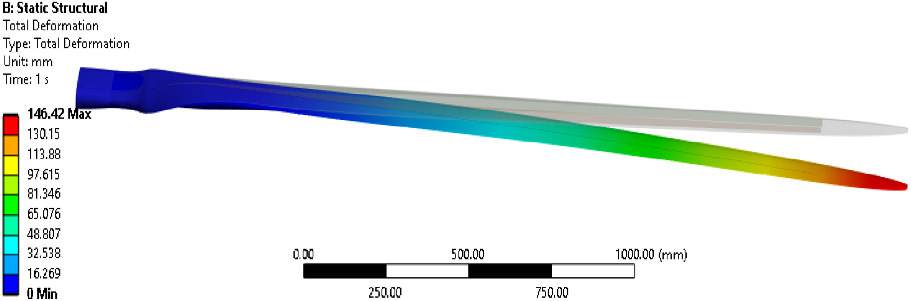
In summary, the evaluation of the blade without the support system and with the specified layup conditions using 0.6 mm thick WCF indicates satisfactory performance in terms of deflection, equivalent stress, and IRF values, affirming its structural integrity and safety under extreme wind load conditions. The subsequent discussion will delve into the comparative advantages achieved by integrating a beam/cable support system into the blade structure.
To illustrate the failure potential of the blade without the support system and underscore the significance of the beam or cable support system, a WCF layup with a thickness of 0.2 mm was employed for both cases. For the blade without support, integrated shell and spar-cup layups consisted of one layer at +45°/−45° for the outer position, one layer at 0°/90° for the middle position, and one layer at +45°/−45° for the inner position, resulting in a total thickness of 0.6 mm for the integrated shell and spar-cups. For the shear-webs, the layup included one layer of WCF at +45°/−45° on one side, a 2 mm honeycomb core at the middle, and one layer of WCF at +45°/−45° on the other side, providing a total thickness of 2.4 mm. A comparative analysis was conducted for fiber layups with and without the support system, considering that ANSYS Mechanical (version 2023 R2) provides IRF results for shell models only. Consequently, the results presented in the figures pertain to the blade shell and shear webs.
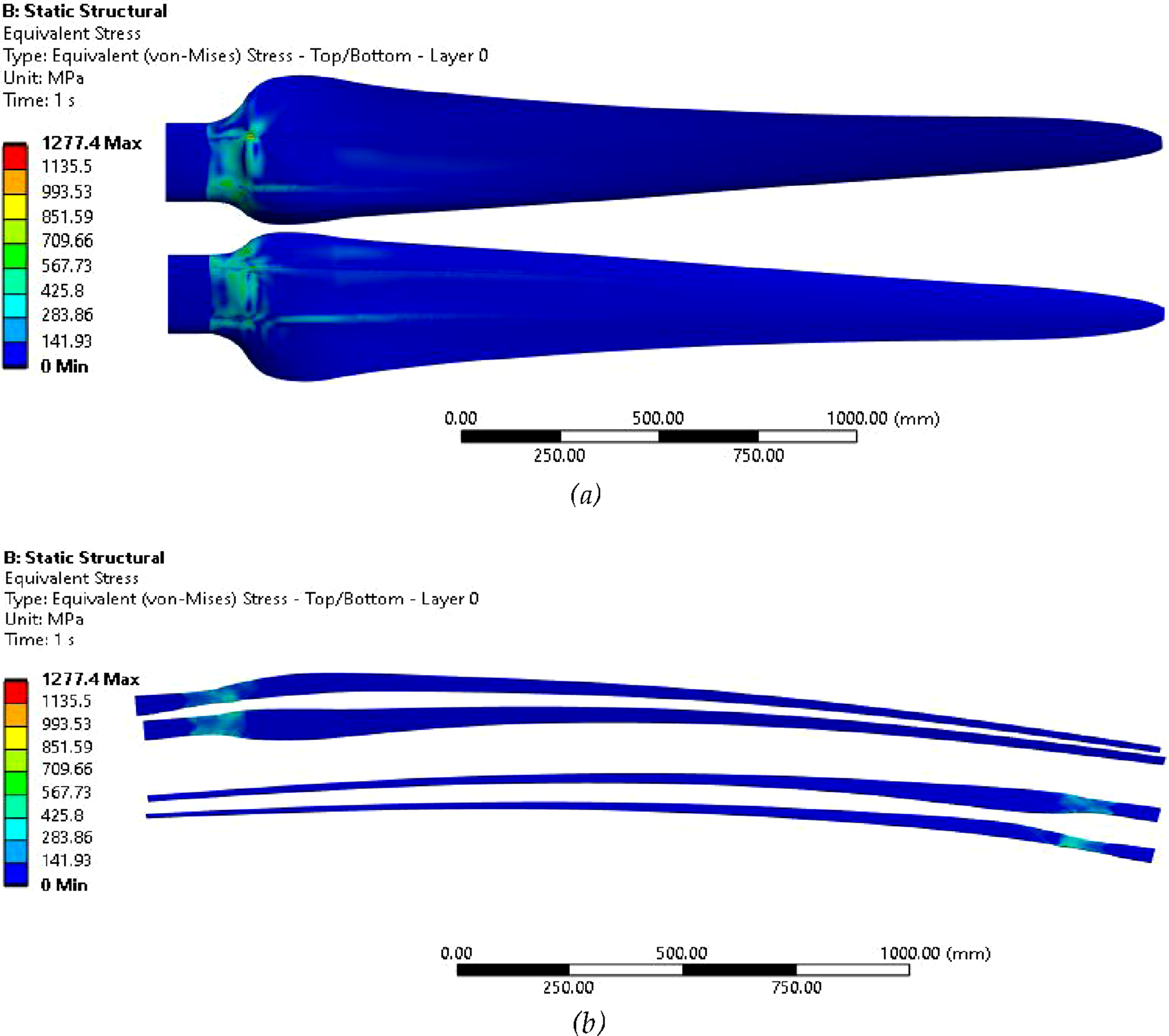
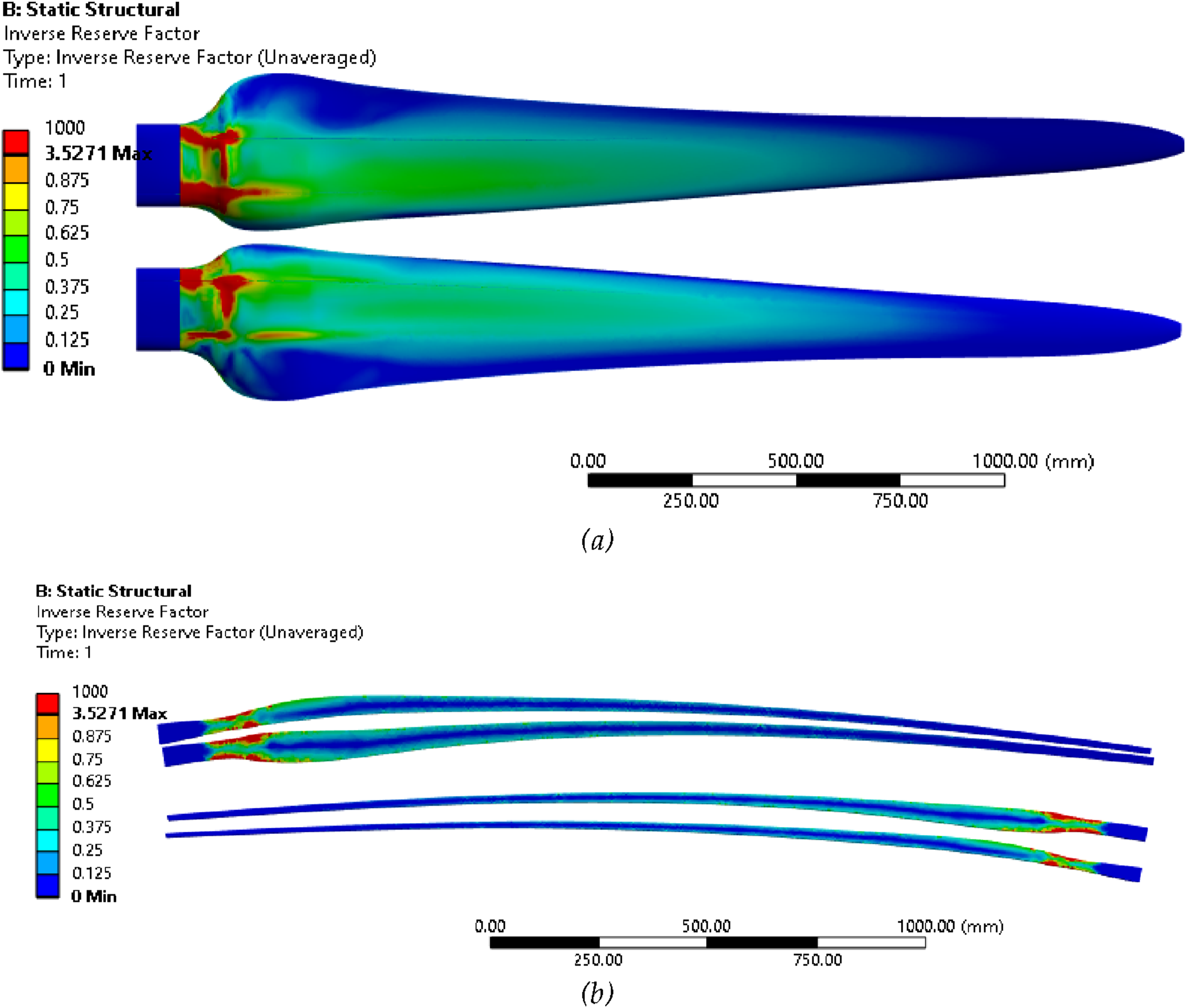
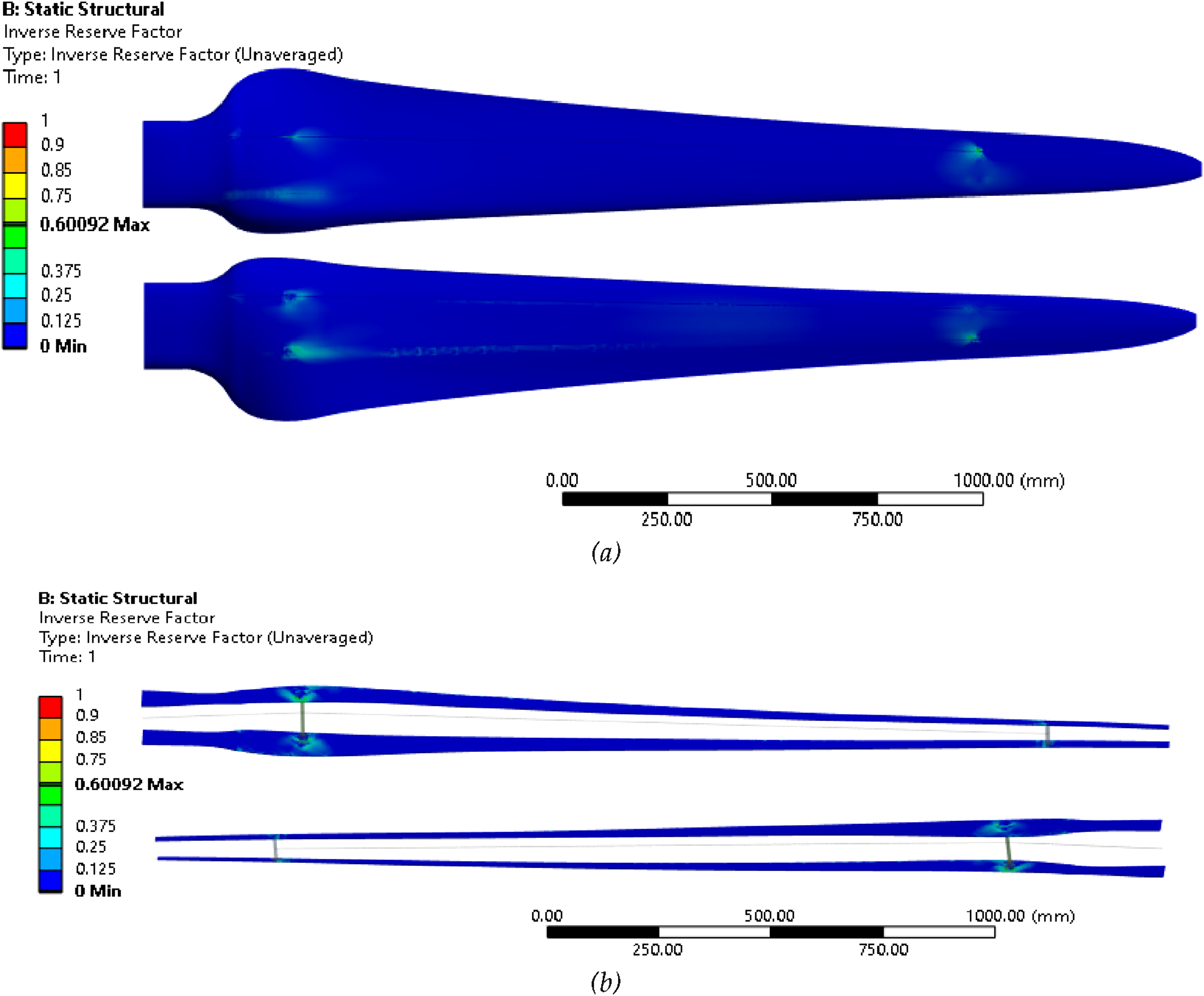
Figure 7 portrays the deflection of the blade without the support system, revealing a maximum value of 509.9 mm, exceeding the 20% limit for cantilevered structures. This substantial deflection would lead to failure due to excessive deformation. The equivalent stress surface plots in Figure 8(a) and (b) illustrate the stress distribution for the shell and spar-cup, and shear webs, respectively. A maximum stress value of 1277.4 MPa is observed, mainly at the root sections of the shell and spar-cups and the shear webs. The IRF values in Figure 9(a) and (b) highlight a maximum value of around 3.5, indicating failure at considerable areas of the root part for both the shell and spar-cups, as well as the shear-webs. A high IRF value indicates that the blade may fail at lower wind load. Therefore, a step-by-step examination of the blade failure at lower loads, relative to the value of the extreme wind load, revealed that failure occurs at 30% of the extreme wind load, specifically at the root part of the shear webs. Figure 10 illustrates the IRF of the shear webs, with the failed area highlighted in red at 30% of the extreme wind load. As the percentage of extreme wind load increases, so does the extent of failure area. At full extreme wind load, the failed areas are depicted in Figure 9. Consequently, without support, a blade with a thickness of 0.2 mm WCF would likely fail due to excessive stress under wind loads lower than those experienced in extreme conditions. Deflection of the blade without support system when using fiber thickness of 0.2 mm. Equivalent stress of blade without support system when using fiber thickness of 0.2 mm: (a) Blade shell and spar-cups; (b) blade shear-webs. IRF of the blade without support system for 0.2 mm fiber thickness: (a) Blade shell and spar-cups; (b) blade shear-webs. IRF of the shear webs for 0.2 mm fiber thickness without support system at 30% of the extreme wind load.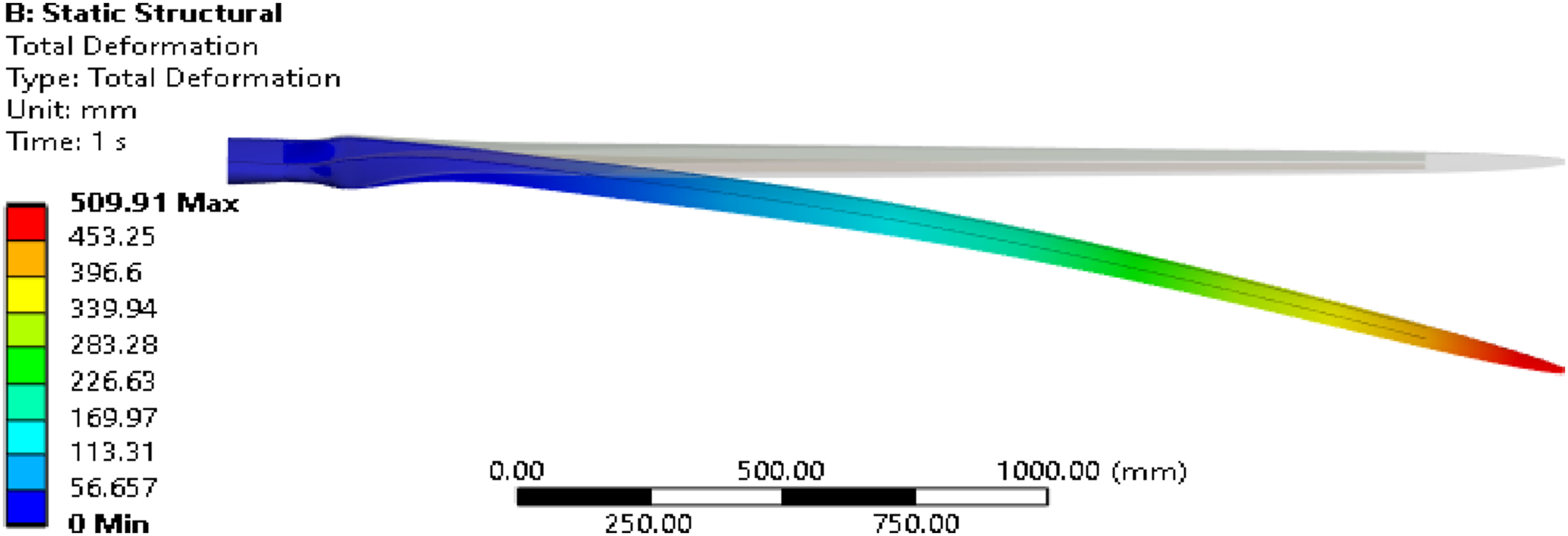
In the same manner, the surface plot results for deflection, stress, and IRF of the blade with the recommended support system, employing a 0.2 mm thickness of woven carbon fiber and the specified layup arrangement, are presented in Figures 11–13. Figure 11 visually represents the deflection of the blade with the support system in comparison to the un-deformed model. A remarkably small maximum deflection value of around 9.1 mm is observed for the blade with the support system. This subtle deflection results in the deformed blade almost coinciding with the position of the un-deformed model, making it challenging to discern them in the presented surface plot in Figure 11. The maximum deflection is concentrated around the mid-part of the blade span, suggesting potential high bending in this region for larger blades. This implies the necessity for additional support points around this position, indicating the potential need for multiple similar support systems as the blade size increases. The tip deflection value remains minimal and closely aligns with its un-deformed position. In comparison with the deflection results of the blade without the support system, a substantial improvement of approximately 98.2% in deflection is achieved with the implementation of the support system. Deflection of the blade with beam/cable support system for fiber thickness of 0.2 mm. Equivalent stress of blade with beam/cable support system for fiber thickness of 0.2 mm: (a) Blade shell and spar-cups; (b) blade shear-webs. IRF of blade with beam/cable support system when using a fiber thickness of 0.2 mm: (a) Blade shell and spar-cups; (b) blade shear-webs.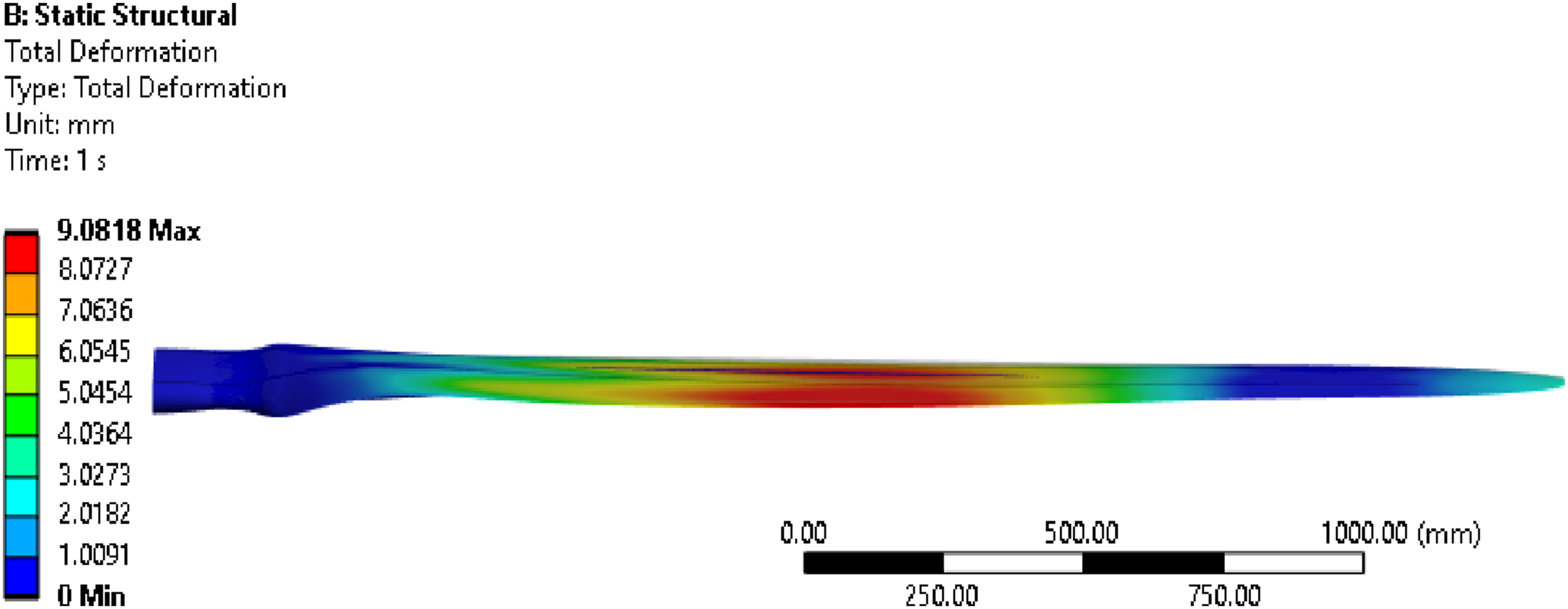
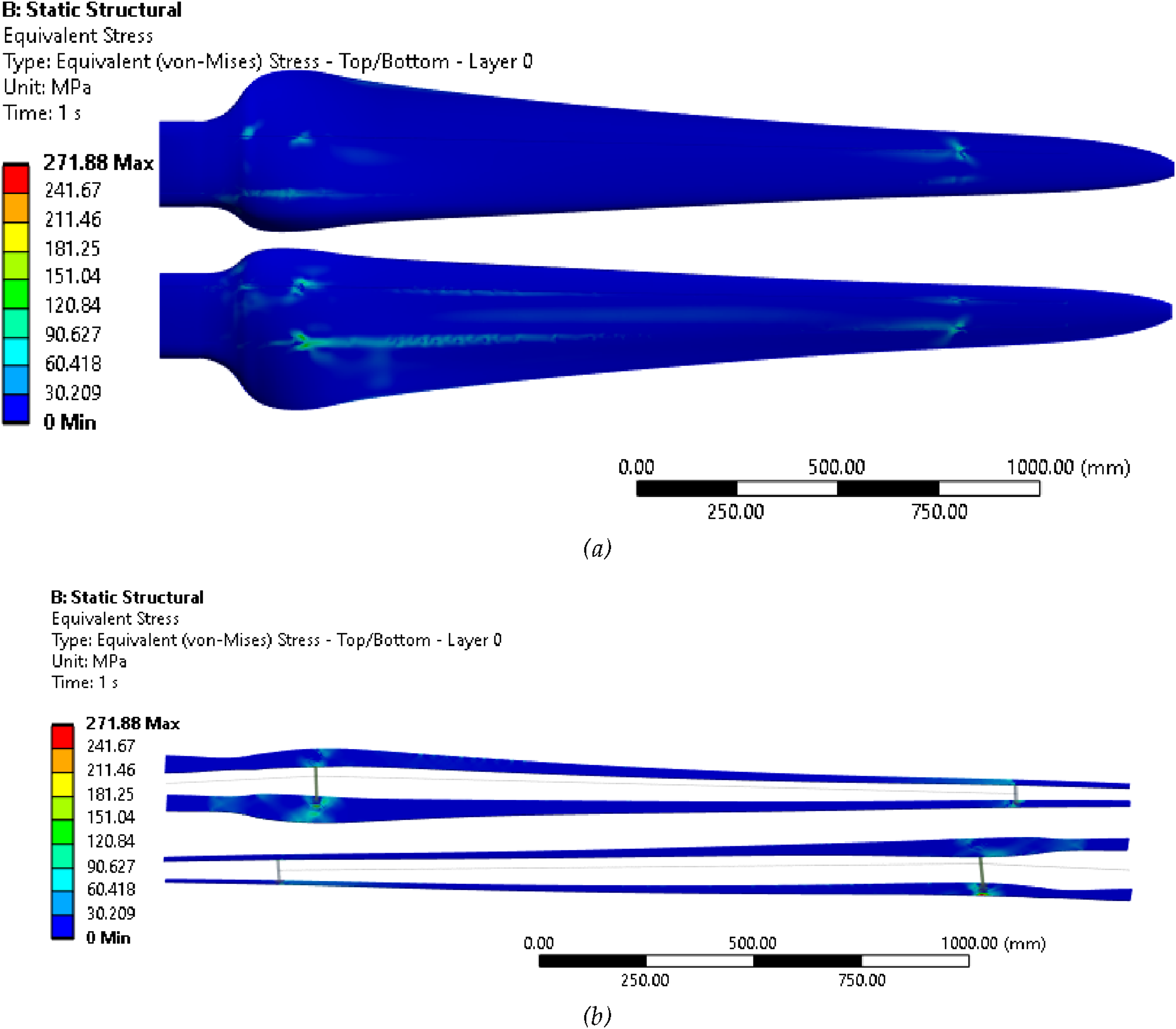
The equivalent stress results are depicted in Figure 12(a) and (b), representing for the integrated shell and spar-cups, and the shear webs, respectively. A maximum stress value of around 271.9 MPa is primarily concentrated in a few areas around the root and support points of the support system, as illustrated in Figure 12. Notably, the elevated stress points around the contact areas of the shear-webs with the added support beam elements, in addition to the root parts, suggest that the support system transfers some loads to these contact areas. Comparing the maximum stress results between the blade with and without the support system reveals a remarkable stress reduction of around 78.7% achieved through the implementation of the support system.
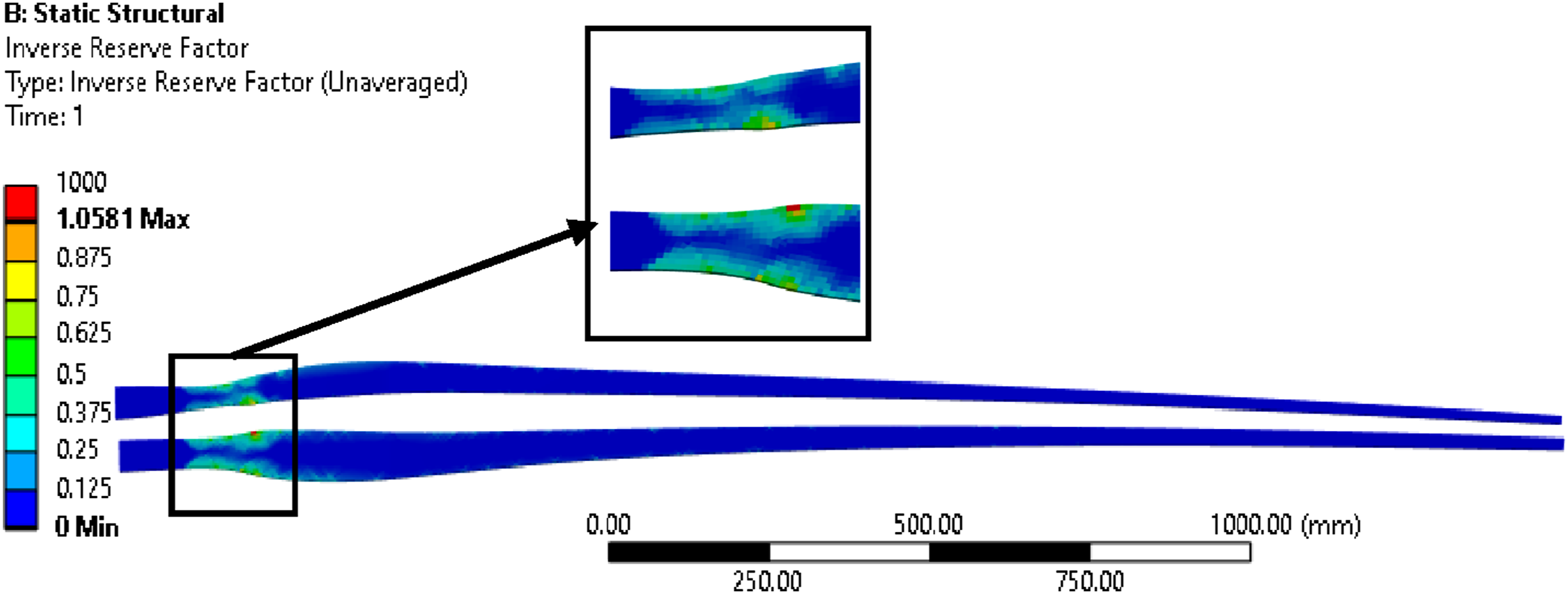
The significance of the improvements lies in the potential safety enhancement if the blade with the support system can achieve a favorable outcome in terms of the failure criteria, specifically the IRF, by reducing it to below one. Figure 13(a) and (b) depict the IRF values of the blade with the support system, considering a WCF thickness of 0.2 mm and the layup arrangements presented above. The result in Figure 13(a) and (b) demonstrates that the cable support system can endure the extreme wind load of 3.2 kPa, with a maximum IRF value of around 0.6 observed at a few points in the shear-webs around the contact areas of the supporting beam elements. Most of the blade surface exhibits very low IRF values, indicating the support system provides substantial relief from extreme load for the entire blade structure. When comparing the maximum IRF value with corresponding result for the blade without the support system, a notable improvement of around 83% is achieved through the implementation of a single beam/cable support system. This improvement highlights the effectiveness of the support system in reinforcing the structural integrity of the blade, ensuring its resilience against extreme wind conditions.
To attain these results, it is essential that the support system efficiently transfers a significant portion of the loads away from the blade, channeling them through the beam/cable support structure to other integral components of the turbine, such as the hub structure. The stress distribution of the shear webs and the beam/cable support system is illustrated in Figure 14, revealing a maximum stress of around 423.5 MPa. The maximum value belongs to the beam/cable support system, comparing to the stress distribution excluding the beam/cable support system in Figure 12, and significantly exceeds the maximum stress on the blade, indicating that the support system is effectively transferring the loads away from the blade to other parts of the turbine. A reaction force of approximately 1.9 kN is recorded at the root of the blade without the support system, while a similar magnitude is observed at the end point of the rod or cable, and around 0.7 kN at the blade root for the blade with the proposed support system. This observation reaffirms the concept of transferring a significant amount of load away from the blade through the utilization of the proposed support system. For wind turbine blades with larger root part, the beam/cable system could be implemented attaching to the front cross beam system only. Equivalent stress of shear webs and beam/cable support system.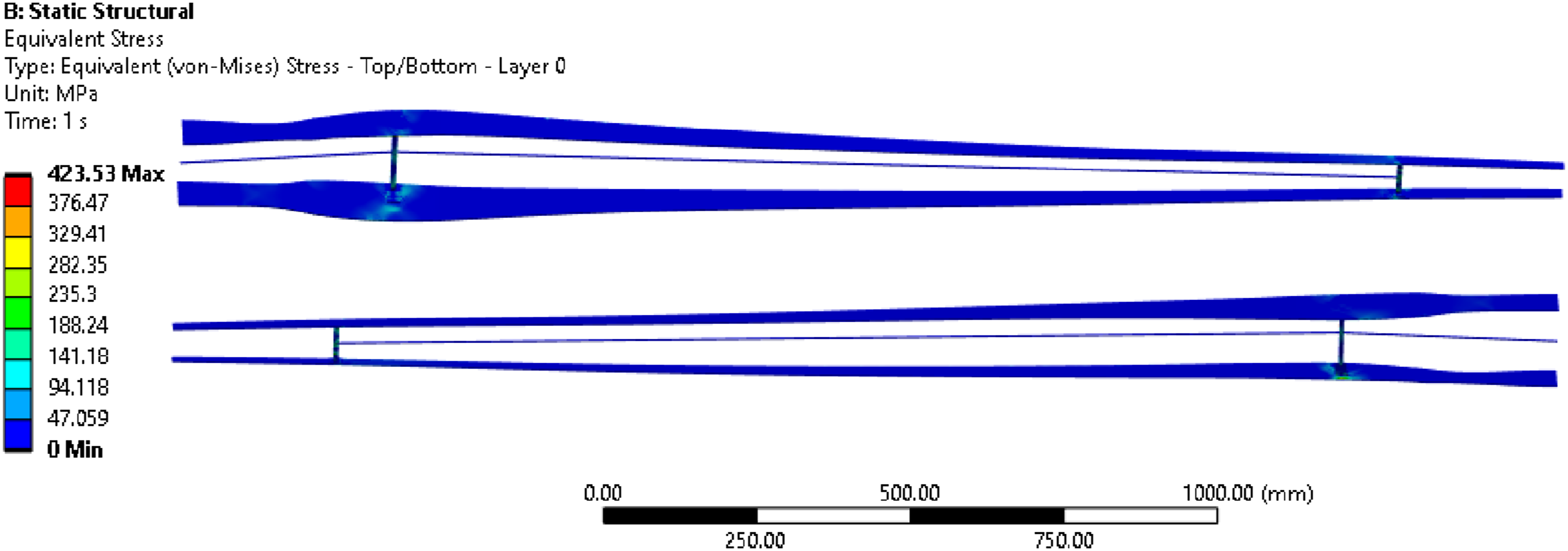
However, the effectiveness of this load transfer mechanism warrants further investigation into the specific arrangements and the overall impact of redistributing loads to other components of the wind turbine. A comprehensive understanding of these interactions will be crucial in optimizing the design and performance of the entire wind turbine system, ensuring its robustness and safety under varying operational conditions. Further studies and analyses will provide valuable insights into the intricate dynamics of load distribution within the turbine structure, enabling the refinement and enhancement of the proposed support system for optimal functionality and longevity.
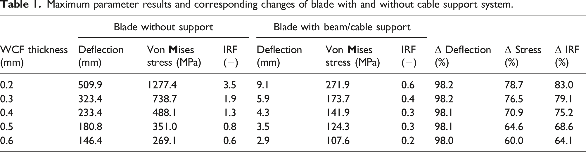
Maximum parameter results and corresponding changes of blade with and without cable support system.
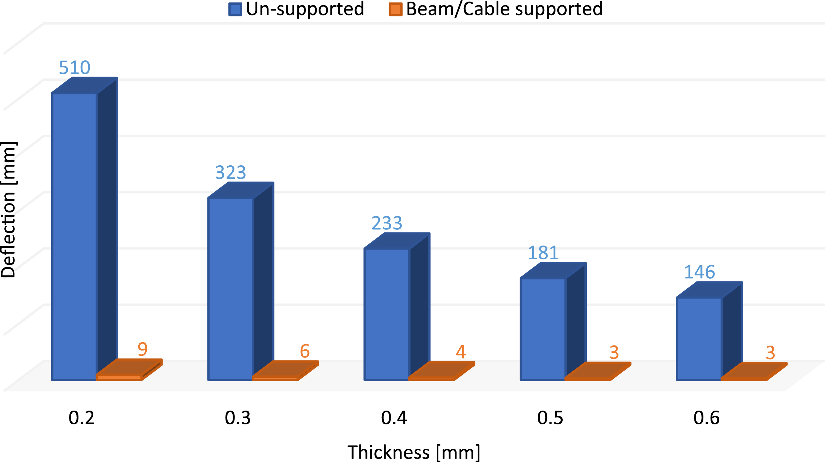
Maximum deflection of the blade with and without support system.
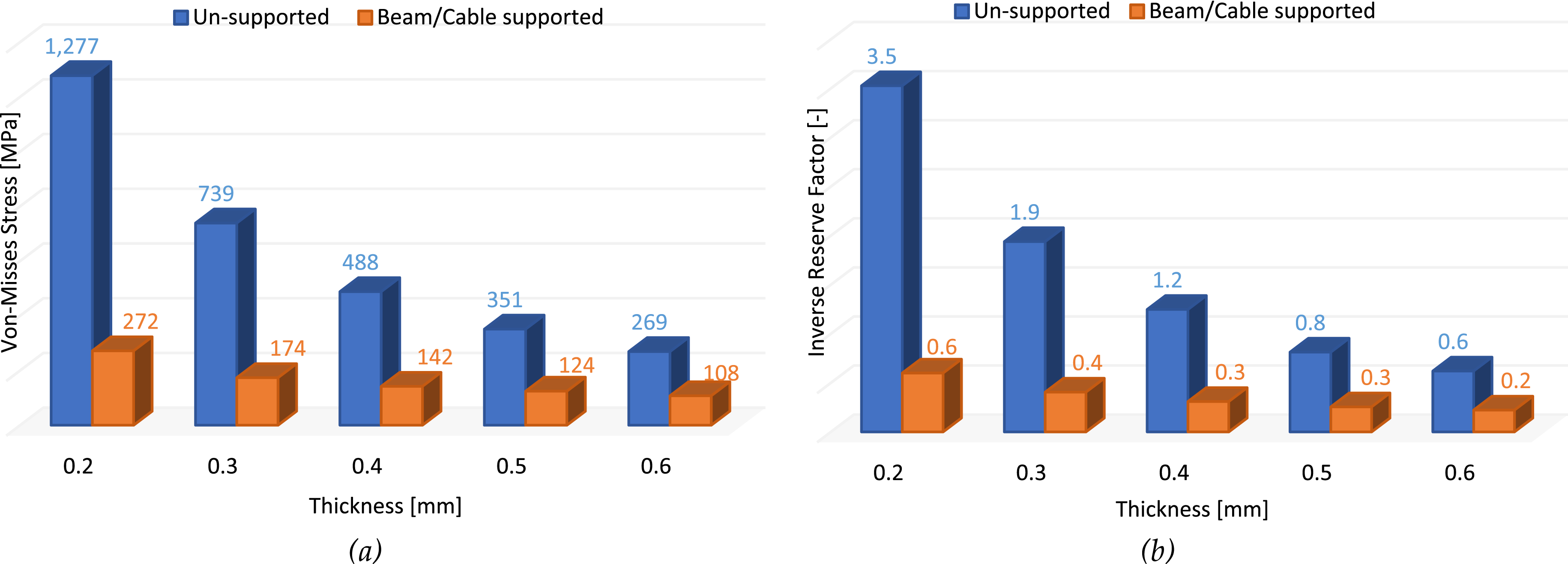
Maximum parameter results of the blade with and without support system: (a) von Mises stress and (b) IRF.
Similarly, the reduction in maximum stress remains high, ranging from 78.7% for 0.2 mm thickness of the fiber to 60% for 0.6 mm thickness, as observed in Figure 16(a). The IRF values shown in Figure 16(b) also demonstrate substantial improvement, varying from 83% to 64.1% with the use of 0.2 mm and 0.6 mm thicknesses of WCF, respectively. The improvement in IRF decreases with increased thickness, with an overall difference of 19.3% between the use of 0.2 mm and 0.6 mm thicknesses. Notably, corresponding decrement is observed for stress, with a difference of 18.7% in improvements. The trend of the decrease in improvement in IRF is particularly notable for thicknesses corresponding to the failed and safe conditions of the blade without the support system, specifically at 0.4 mm and 0.5 mm thicknesses of WCF. Moreover, the maximum stress and IRF values of the blade with the support system at a WCF thickness of 0.2 mm are shown to be comparable to the corresponding values of the safe blade without a support system at a thickness of 0.6 mm, as depicted in Figure 16(a) and (b) respectively. Hence, significant thickness reduction of approximately 70% would be achieved through the implementation of the proposed beam/cable support system, which implies a corresponding weight reduction of similar magnitude.
Therefore, in the wind energy industry, prioritizing safety, structural integrity, and cost efficiency are paramount for ensuring sustained progress. The considerable advancements achieved through the implementation of the beam/cable support system underscore its potential to enhance safety and reduce the utilization of fiber materials, even under safe design conditions. Moreover, it enhances the aerodynamic performance by protecting the reduction of the effective swept area during bending insuring sustainable energy harnessing capability of wind turbines. The support system is also applicable to large wind turbine blades, with the potential for optimized placement of support points or an increased number of the beam/cable system within the blade structure.
It is worth noting that the study currently focuses on extreme wind loading in one direction, and similar positive outcomes are anticipated for symmetric arrangements of the beam/cable support system under flap-wise and edgewise loadings. While the numerical simulations provide valuable insights, experimental studies are recommended to compare the attained results. Additionally, exploring the impact of load transfer from the blade to other components, such as the hub, is an avenue for future investigation. Comprehensive studies of the proposed support system should extend to extreme wind conditions not addressed in this study, as well as other loading scenarios.
Moreover, delving into the effects of the additional beam/cable support system on the dynamics and natural frequencies of wind turbine blades is an essential area for future research. Understanding these aspects will contribute to a more holistic assessment of the proposed system’s performance and its potential implications for the overall structural behavior of wind turbines. Continued research efforts in these directions will undoubtedly contribute to the ongoing improvement and optimization of wind turbine design for enhanced safety and cost-effectiveness.
Conclusion
Extreme wind loads continue to be a primary cause of structural failures in wind turbines, with the blades—particularly their flap-wise bending behavior—being the most vulnerable component under such conditions. These failures, especially during both parked and operational states, not only result in high maintenance costs and operational downtime but also significantly reduce the overall efficiency and economic viability of wind energy systems. Given that blade-related issues are among the most frequent and costly, enhancing structural resilience against these loads is a critical design priority.
This study introduces a novel passive load mitigation strategy by incorporating an internal beam/cable support system into the blade architecture. The system is designed to offload and redistribute stresses away from the primary fiber-reinforced composite structure, reducing vulnerability without compromising the blade’s weight efficiency. Through a comprehensive numerical analysis using finite element tools (ANSYS ACP and Mechanical, 2023 R2), this work demonstrates that the proposed system yields significant structural benefits. These include a marked reduction in blade deflection, maintaining it well within acceptable design limits, along with a decrease in maximum stress across various fiber layups. Most importantly, the structural safety margin—evaluated through the inverse reserve factor—shows a significant improvement, indicating a greatly enhanced resistance to failure under extreme loading conditions.
The principal contribution of this study lies in the integration of this lightweight, structurally efficient support system, which enables blades to better withstand extreme wind conditions without a proportional increase in material cost or complexity. Beyond improved mechanical performance, the approach also holds potential for material savings by reducing the required fiber volume in the blade design, which is particularly valuable in large-scale turbines where cost and weight optimization are paramount.
From a practical perspective, this system could be especially beneficial for smaller turbines operating in remote or harsh environments where reliability is crucial and maintenance access is limited. For utility-scale turbines, the system presents a pathway toward enhancing structural reliability and extending service life, ultimately supporting more consistent energy production and lower lifecycle costs.
However, while the numerical results are promising, the findings must be interpreted within the scope of the simulation environment. Experimental validation is essential to confirm these benefits under real-world conditions. Moreover, the current study does not fully capture the impact of load redistribution on other components, such as the hub and nacelle. Understanding the system-wide implications of this load transfer remains a critical next step. Additionally, the aerodynamic performance implications of the added internal structure were not addressed and should be evaluated in future studies.
Looking ahead, future research should aim to explore the dynamic response of blades equipped with the beam/cable system, including their modal characteristics and behavior under multidirectional, time-varying loads. Investigating system behavior across a wider range of blade sizes, materials, and loading scenarios—such as gust, turbulence, and off-design conditions—will further validate and refine the applicability of this concept. Optimization studies considering cost, manufacturability, and fatigue performance would also support the path toward practical deployment.
In conclusion, this research provides a meaningful step forward in the development of structurally robust and cost-effective wind turbine blades capable of withstanding extreme wind events. The proposed support system not only demonstrates technical viability but also aligns with the broader goals of improving energy reliability, reducing maintenance burdens, and supporting the expansion of sustainable wind energy. Continued interdisciplinary efforts in structural mechanics, materials science, and wind engineering will be vital to fully realize the potential of such innovations in the rapidly evolving landscape of renewable energy technologies.
Footnotes
Author contributions
Conceptualization, H.K.K., M.B.K., and T.K.N.; data curation, H.K.K.; formal analysis, H.K.K.; funding acquisition, M.B.K., and T.K.N.; investigation, H.K.K.; methodology, H.K.K.; project administration, M.B.K.; resources, H.K.K., and M.B.K., and T.K.N.; supervision, T.K.N., and M.B.K.; validation, H.K.K.; visualization, H.K.K.; writing—original draft, H.K.K.; writing—review and editing, H.K.K., M.B.K., and T.K.N.
Declaration of conflicting interests
The authors declared no potential conflicts of interest with respect to the research, authorship, and/or publication of this article.
Funding
The author(s) disclosed receipt of the following financial support for the research, authorship, and/or publication of this article: the study received financing partially from Norhed II project and NTNU for financing the article processing fee.
Data Availability Statement
Data will be available upon reasonable request.