
Abstract
Background:
Designed by Dr. Sethi, the Jaipur Foot prosthesis is ideally suited for amputees in developing countries as it utilizes locally sourced, biodegradable, inexpensive materials and is focused on affordability and functionality. To date, however, no data have been reported on the material properties of the foot components.
Objectives:
The goal of this work was to evaluate mechanical properties of the Jaipur Foot components to guide foot design and manufacturing and reduce weight.
Study Design:
Experimental.
Methods:
Mechanical testing was conducted on two types of woods (ardu and cheed), microcellular rubber, tire cord, cushion compound, tread compound, and skin-colored rubber. Each material was subjected to testing in either tension or compression based on its location and function in the foot. Samples were tested before and after vulcanization. Two-sample t-tests were used to assess statistical differences.
Results:
Cheed compressed perpendicular to the grain had a significantly higher modulus of elasticity than ardu (p < 0.05); however, cheed had a higher density. Vulcanization significantly increased the modulus of skin-colored rubber, cushion compound, and tread compound (p < 0.05) and decreased the moduli of both microcellular rubber and tire cord (p < 0.05).
Conclusion:
The material property results from this study provide information for computer modeling to assess material construction on overall foot mechanics for design optimization. Ardu wood was ideal based on the desire to reduce weight, and the tire cord properties serve well to hold the foot together.
Clinical relevance
With new knowledge on the material properties of the components of the Jaipur Foot, future design modifications and standardized fabrication can be realized, making the Jaipur Foot more available on a global scale.
Introduction
Innovative prosthetic technology has greatly extended human capability over time as the understanding of biomechanics and new materials have increased. As the technology has improved, so has the opportunity to create prosthetic devices that fit the needs of individual populations and lifestyles. Lower prosthetic limbs, such as the widely available solid-ankle cushion-heel (SACH) foot, are popular in Western “chair-sitting” and “shoe-wearing” cultures. Western feet tend to be made with a rigid keel, like the SACH foot, and do not allow amputees to sit, squat, sit cross-legged, or walk barefoot.1,2 Arya et al. 2 also noted that the Jaipur Foot is more stable when compared with the SACH and Seattle foot using ground reaction forces. In addition, Western prostheses are too expensive for low- and middle-income amputees across the globe. 3 Sethi et al. 1 recognized these problems and developed the Jaipur Foot in the 1970s with the purpose of providing rural Indian amputees with a durable, low-cost prosthetic foot that is both functional and culturally acceptable. The Jaipur Foot focuses on value for money and functional use and was designed to meet the needs of many Indian amputees including the ability to squat, sit cross-legged, and walk barefoot in muddy and uneven terrain. The foot is manufactured for under US$10, 4 utilizing local, biodegradable, 5 and inexpensive materials, making it financially accessible to amputees who could not previously afford a prosthesis.
The full design and fabrication process was previously described in detail by Sethi et al. 1 In brief, the Jaipur Foot consists of three separate blocks wrapped in layers of various rubbers. Wood is used for the ankle block, and both the heel and forefoot blocks are microcellular rubber (MCR). The flexibility of the rubber blocks, compared to the rigid blocks found in the SACH foot, allows for multi-directional movements with the Jaipur Foot, most notably dorsiflexion which allows the amputee to squat. 6 Each block is hand shaped and then wrapped in tire cord, a composite of aligned reinforcing cords in a rubber compound, and a rubber cushion compound before being joined together. A layer of tread compound is added to the bottom of the foot for increased durability before the entire foot is wrapped in a skin-colored rubber and vulcanized (Figure 1). The vulcanization is completed to adhere the various layers and components into a solid foot. This skin-colored rubber adds to the esthetic appeal allowing it to look similar to a human barefoot. This is important to many amputees who are regularly shoeless, and the rubber additionally provides a water resistant protective exterior.
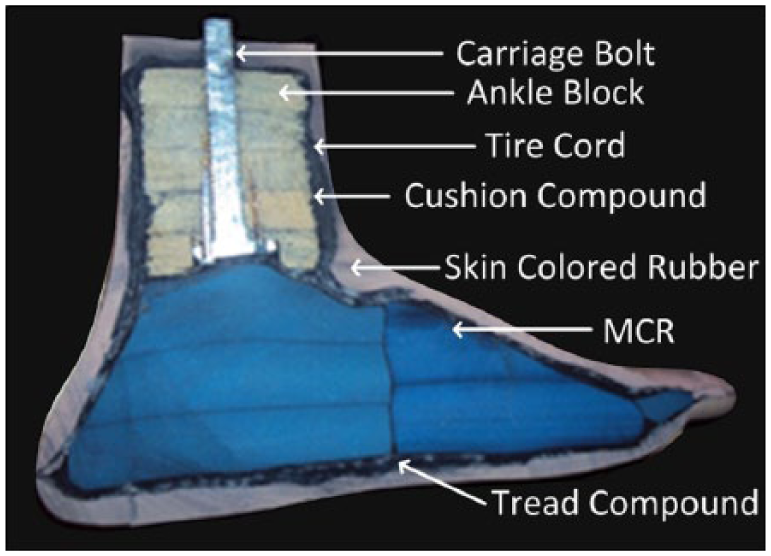
Photograph of a sagittal-plane cross-sectional view of the Jaipur Foot.
The material properties of the raw materials and how manufacturing (i.e. vulcanization) changes these specific properties remain unknown despite the widespread use of the Jaipur Foot prosthesis. Materials that are used for fabrication are selected from the open market based on availability and cost. The objective of this study was to assess the material properties of materials utilized in the Jaipur Foot. These data could be incorporated into a finite element analysis of the Jaipur Foot to identify regions of higher and lower load and deformation. Finite element analysis (FEA) could be used to optimize the geometric design and material selection, with the goal of reducing the weight and improving the mechanical function of the prosthetic limb. This work could also be used to set quality benchmarks for materials purchased for foot manufacturing. FEA allows for systematic assessments of material properties on global foot function.7,8 Currently, no evaluation of quality or composition is performed on the materials being purchased in local Indian markets for use in manufacturing of the foot. Regulating the quality of the materials could improve the consistency of the foot’s durability and performance. Eventually, a protocol could be created for buyers to use when purchasing raw materials and modulus values could be used as a metric to evaluate if a batch of material is appropriate for use in manufacturing.
Methods
All materials used in the Jaipur Foot were tested using a uniaxial material tester (Instron model 5967, Instron Corporation, Canton, MA) with a 30 kN load cell (Instron model 2580-202, Instron Corporation) in Jaipur, India (Table 1). The materials were obtained from the open market in around Jaipur, India. The materials were not procured from a single source, but rather purchased as would be done clinically to manufacture the feet, which chooses a vender based on availability and price. Each material was subjected to testing in either tension or compression based on its location and function in the foot. MCR, tire cord, cushion compound, tread compound, and skin-colored rubber were also tested in two conditions: pre and post vulcanization. The materials were vulcanized in a 145-A laboratory high-pressure vertical autoclave (Delhi, India) for 3 h at a temperature of 120°C and an average pressure of 119 kPa at a Jaipur Foot factory. Wood was only tested before vulcanization. During fabrication of the foot construct, the wood is completely covered with rubber; hence, the wood is not directly exposed to the vulcanization chamber moisture.
Testing dimensions (unvulcanized and vulcanized) and parameters used for all mechanical testing.
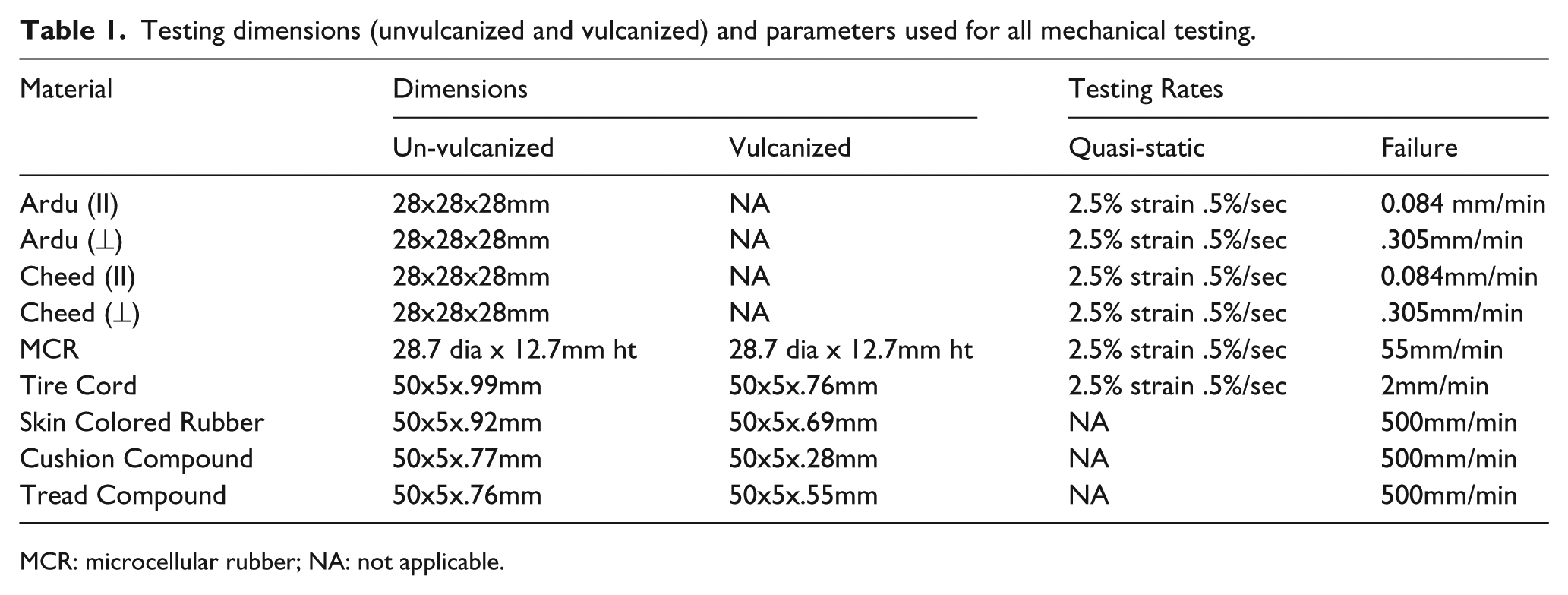
MCR: microcellular rubber; NA: not applicable.
Five samples of MCR, ardu, cheed, and tire cord under each condition were tested in quasi-static settings and then to failure. The quasi-static testing strained each specimen to 2.5% engineering strain at a rate of 0.5%/s. 9 Samples were then tested until failure at a material-specific rate (Table 1), determined by ASTM standards (ASTM Standard D143-14 or D1056-14). Skin-colored rubber, tread compound, and cushion compound were only tested to failure due to the lower limits of the force transducer exceeding the small loads of these rubbers under quasi-static conditions.
Compression testing
MCR, ardu, and cheed were tested in compression, as they are the main compressive load-bearing components of the Jaipur Foot. Ardu and cheed wood were tested in compression parallel and perpendicular to the grain. The size of the wood samples was selected from the ASTM Standard D143-14 and was 28 mm3. Ardu and cheed samples from a single plank were tested parallel to the grain at a strain rate of 0.084 mm/min and a rate of 0.305 mm/min in the perpendicular direction determined from ASTM Standard D143-14. 10 Samples of both unvulcanized and vulcanized MCR were machined to cylindrical disks of 28.67 mm diameter and 12.7 mm height in accordance with ASTM Standard D1056-14. 11 After being tested under quasi-static conditions, both the unvulcanized and vulcanized MCR samples were tested at a rate of 50 mm/min to failure.
Compression analysis
Force-displacement data from all compression tests, both quasi-static and failure, were converted into engineering stress and strain values and were used to calculate Young’s modulus. Given the non-linearity of the curves, we chose to determine two moduli values for the wood samples. The modulus was evaluated from the best-fit line (polyfit function within MATLAB, The Mathworks Inc., Natick, MA) to the stress–strain curve between 0.06 MPa and 0.26 MPa stress (low-strain region; Figure 2). The modulus was also evaluated as the best-fit line (least square regression, Linear fit, Microsoft Excel) to the stress–strain curve between 1.1 and 0.9 MPa below the yield stress or 1.1 and 0.9 MPa below the maximum stress (high-strain region) achieved if yield was not reached (Figure 2).
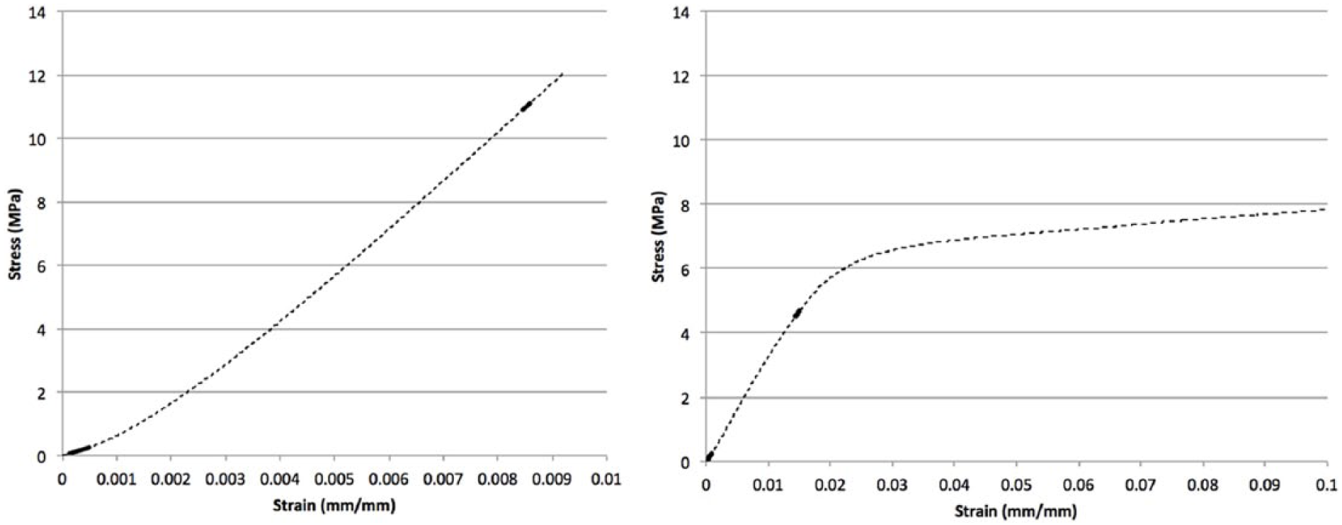
Modulus regions for wood samples. Left: cheed wood in parallel that reached maximum stress before yield. Right: cheed in perpendicular that reached yield during testing. Complete data are dashed line. Dark solid lines are lower and upper moduli regions.
Young’s modulus was calculated for both unvulcanized and vulcanized MCR samples under quasi-static conditions using a best-fit line (least square regression, Linear fit, Microsoft Excel) to the stress–strain data within 1.5%–2.0% strain (low-strain region). The modulus for both MCR’s compression to failure tests was evaluated from the best-fit line (least square regression, Linear fit, Microsoft Excel) to the data between 2.0% and 8.0% strain (high-strain region). These data also provided yield strength to be calculated for the unvulcanized MCR in full compression using a 0.2% offset.
Tension testing
Tire cord, skin-colored rubber, cushion compound, and tread compound were all tested in tension, both pre and post vulcanization (n = 5). All specimens for tensile testing were cut as straight rectangles from a single sheet of each material with a length of 150 mm, a gauge length of 50 mm, and a width of 5 mm. The thickness of the samples was left as the natural thickness of the sheet of each material (Table 1). Tire cord was tested to failure at a displacement rate of 2 mm/min. 12 The skin-colored rubber, tread compound, and cushion compound were all tested at a rate of 500 mm/min. 13
Tension analysis
Young’s modulus was evaluated from the quasi-static conditions for both unvulcanized and vulcanized tire cord. The modulus for both unvulcanized and vulcanized tire cord in quasi-static tests were calculated using stress–strain values between 1% and 1.5% strain, which was the linear regions of the curve. When tested to failure, the modulus of tire cord was calculated between 0.75% and 1.25% strain for unvulcanized and between 2% and 4% strain for vulcanized samples, as these regions exhibited linear behavior. The yield strength was found using a 0.2% offset. Ultimate strength was also determined from the stress–strain data for all unvulcanized and vulcanized samples of tire cord.
Tension for the skin-colored rubber, cushion compound, and tread compound all resulted in force values much lower than those recorded for other materials or testing performed in compression. Since the testing system was limited with a 30 kN load cell, these data sets had more noise due to the working range of the load cell, and thus the stress–strain data for these materials were filtered in MATLAB (The Mathworks, Inc. Natick, MA) using a polynomial Savitzky–Golay filter (polynomial order 1 and frame size 31) for smoothing. The Savitzky–Golay filter was selected, as it is commonly used to increase signal to noise ratio without greatly distorting the signal. The higher frame size was chosen, since the data acquisition was high, and the order size of 1 was selected, as the data were expected to be linear. No optimization was used when deciding on filtering process. The Young’s modulus, yield strength, and ultimate strength were then extracted from the filtered data. The moduli for these three compounds were calculated using the 1%–3% strain region of the stress–strain data. The 1%–3% was selected for modulus calculations, as this was the linear region of the data.
Poisson’s ratio and density
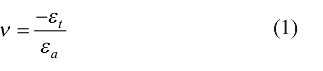
All failure tests were video recorded (HERO4 Silver GoPro, San Mateo, CA) to calculate Poisson’s ratio. Images were extracted from the video, one from before testing began and another before failure was observed, and imported into ImageJ (National Institutes of Health (NIH), Bethesda, MD) with FIJI package. Measurements were taken in the transverse and axial direction in each image and Poisson’s ratio was calculated using equation (1), where ν represents Poisson’s ratio and the transverse and axial strains are εt and εa, respectively. Equation (2) was used to calculate strain with dl being the change in length and L representing the original length. Poisson’s ratio values were not acquired for unvulcanized tire cord and wood samples tested parallel to the grain, as changes in dimensions were not observed under the given testing conditions. Material density was calculated using the mass and volume of each sample before testing
Statistical analysis
Two-sample t-tests were conducted between selected modulus values to determine significant differences. For wood samples, parallel moduli were compared to perpendicular moduli for all three (quasi-static, lower, upper) sets of values. The difference between the moduli of perpendicular cheed and perpendicular ardu was also calculated. For MCR, tire cord, skin-colored rubber, cushion compound, and tread compound, t-tests were performed between each material’s unvulcanized and vulcanized samples to determine significance of vulcanization on their material properties. All statistical analyses were carried out using Microsoft Excel, Data Analysis toolset. Averages of the five samples tested were used for statistical comparison.
Results
A summary of the complete testing table can be seen in Table 1. Young’s modulus of ardu under quasi-static compression in parallel and perpendicular orientations was not found to be statistically different (p = 0.18; Figure 3). When comparing the low-strain region and high-strain region modulus values from failure testing, ardu did have significantly greater modulus values when compressed parallel to the grain (p < 0.01 in both cases, Figure 3). The only significantly different modulus between parallel and perpendicular orientations for cheed was the upper modulus (p < 0.01, Figure 3). When tested to failure perpendicular to the grain, ardu had yield strength of 3.37 ± 0.40 MPa and cheed had a yield strength of 5.63 ± 1.68 MPa. The low strain moduli of perpendicular cheed and perpendicular ardu were compared, and cheed was found to have a statistically higher modulus (p < 0.01, Figure 3).
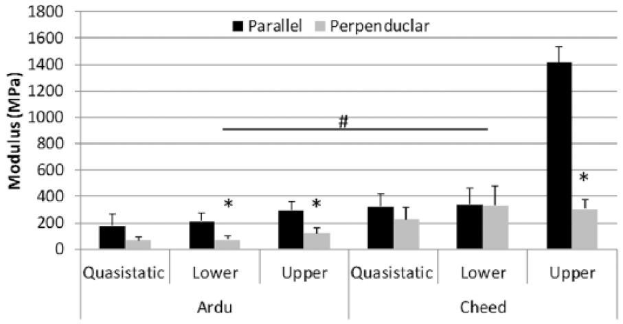
Modulus values for all wood tested (mean and SD).
Vulcanization was found to have a statistically significant effect on all the materials’ modulus values, except the tire cord when tested under quasi-static conditions (p = 0.5814; Table 2 and Figure 4). Specifically, vulcanization increased the modulus in most materials; however, MCR both in quasi-static (p < 0.01) and to failure conditions (p < 0.01) had the modulus significantly reduced by the vulcanization process. In addition, when tested to failure, tire cord also had a significantly lower modulus once vulcanized (p < 0.01). Tire cord had considerably higher modulus, yield strength, and ultimate strength properties than any of the other materials tested in tension. Interestingly, cheed had the lowest average Poisson’s ratio value at 0.08 and ardu had the highest at 0.46 (Table 3). Density for all materials ranged from 0.25 g/cm3 (unvulcanized MCR) to 4.31 g/cm3 (vulcanized cushion compound; Table 3). It is important to note that the MCR did not yield under the loading conditions tested; hence, some of the data are missing for MCR.
Summary of material properties for all rubbers (mean ± SD).
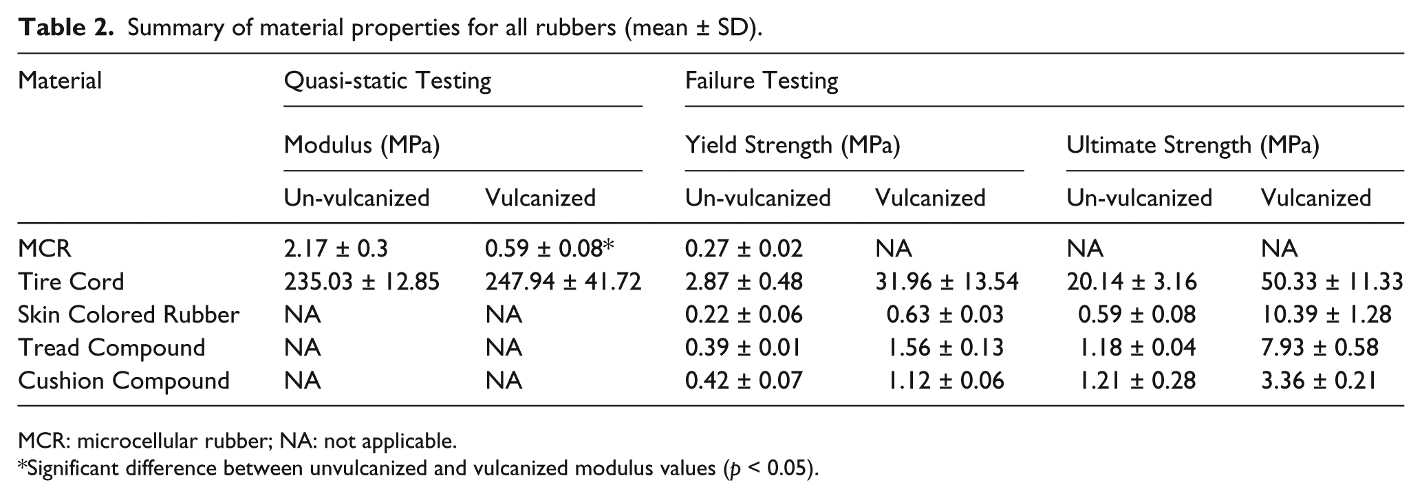
MCR: microcellular rubber; NA: not applicable.
Significant difference between unvulcanized and vulcanized modulus values (p < 0.05).
Poisson’s ratio and density values for all materials (mean ± SD).
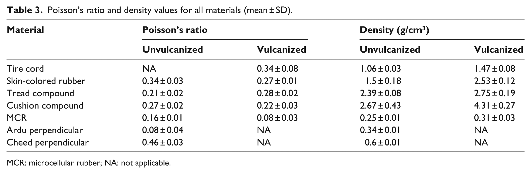
MCR: microcellular rubber; NA: not applicable.
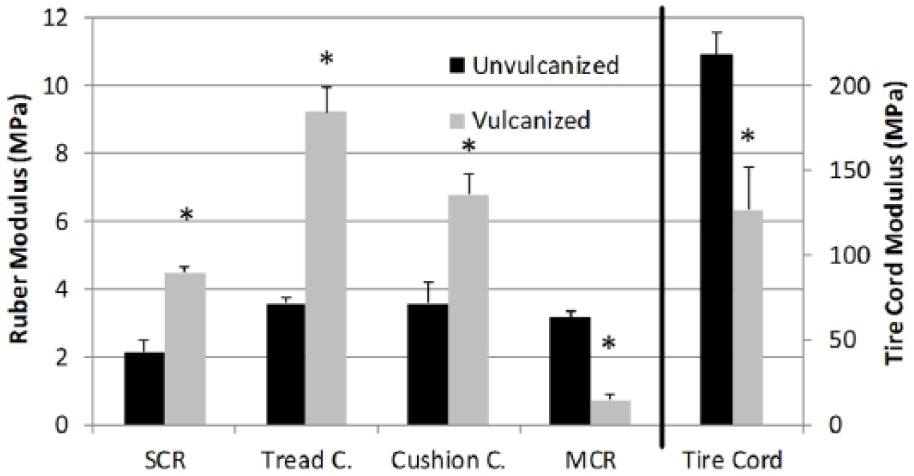
Modulus values for all rubbers tested unvulcanized and vulcanized (mean and SD). Tire cord modulus values on the left axis all other on the right.
Discussion
This work presents the first investigation of the mechanical properties of the materials obtained and utilized in the fabrication of the Jaipur Foot. As these materials were obtained at numerous different local markets in Jaipur, India, composition cannot be absolute, and comparisons with published data characterizing Young’s modulus of these materials are challenging. This is, however, the regular procedure that is used to manufacture clinical prosthetic feet. Both cheed and ardu had considerably higher moduli in compression than moduli found in literature,14,15 but this could be due to regional variations. Cheed is a type of cedar, so the closest comparison for modulus is to these cedars, which are anywhere from 13,700 to 43,500 kPa, parallel to the grain and between 1600 and 5000 kPa perpendicular to the grain. Cheed compressed parallel to the grain had an upper modulus far greater than other modulus values for wood reported within this study. The observed Young’s modulus of MCR in this study agrees well with other low-density MCRs in compression with observed values between 1 and 5 MPa. 16 The modulus values for unvulcanized tire cord in tension were also consistent with previously established values in literature of 200–300 MPa. 17
Cheed has a significantly higher modulus at large strains, compared to ardu when tested perpendicular to the grain, but both woods have moduli that exceed all other materials in the foot. In an epidemiological study of Jaipur Foot failures, the wood component was not the primary mode of failure; hence, we suggest that the choice of wood should likely be more heavily dependent on weight versus modulus. 18 Cheed has a higher density (approximately double) and would contribute more weight to the foot than a comparable ankle block made of ardu. With weight reduction being a large priority, the increased, but unnecessary, strength of cheed does not offset the addition of extra weight. Ardu is recommended as the primary wood type to be used in manufacturing the Jaipur Foot moving forward.
Vulcanization significantly increased the modulus of the skin-colored rubber, cushion compound, and tread compound, as expected. 19 The modulus of MCR decreased substantially with vulcanization. It is likely that vulcanization of the entire foot piece increases the compliance and flexibility of the MCR forefoot and heel blocks. Contrary to the original foot design, when the forefoot and heel blocks were composed of two grades of MCR, the current manufacturing process uses only low-density MCR. One design aspect to consider in the future is to combine the forefoot and heel blocks into a single solid block of MCR. Tire cord’s moduli were also decreased significantly by vulcanization when pulled to failure, yet still had a much greater modulus than any of the other materials that wrap the core blocks of the Jaipur Foot. This confirms that tire cord is a critical compound in providing strength and durability to the foot design.
While we have characterized the material properties of the individual components, the next step to improve the Jaipur Foot would be to extend this work in two directions. First, these data serve as input to a computer model of the foot that can be used to better simulate the complex loading conditions seem by the foot as a whole and allows for a simple parametric study of the materials and geometries of each component for how they affect foot behavior. Once the model is validated, the model could be used to complete a parametric study to determine how slight fluctuations in material properties affect the overall behavior of the foot under complex loading scenarios. This would then drive quality control parameters for material selection during manufacturing. The model could also be used to optimize thickness of the rubber layers or to test one piece of MCR versus two separate pieces and how the foot function is affected. Second, we believe simple mechanical testers could be built that can be taken to the market to quickly assess the material properties of the component parts and determine if they are of sufficient properties to result in a functioning Jaipur Foot. The computer model will be able to give us a range of properties that still results in similar foot performance. It is important to point out that others have suggested that ultimately a prosthetic foots functionality should be tested to determine the Amputee Independent Prostheses Properties (AIPP).20,21 This essentially requires testing of the entire foot as one as opposed to testing individual components. This is currently underway with the Jaipur Foot.
This study is not without limitations. The material selected to test was only from the Jaipur area of India, and thus, may not be representative of several different large manufacturing units throughout the whole country. In addition, not all materials were evaluated under all possible conditions. One instance of this was the inability to test vulcanized wood. Blocks of wood were vulcanized, but vulcanizing the bare wood dramatically changed the moisture content and is not representative of the actual manufacturing process in which the wood is protected by being wrapped in layers of rubber. Poisson’s ratio was unable to be calculated for unvulcanized tire cord and wood samples tested parallel to the grain. In both cases, no noticeable change in sample dimensions could be observed under the loads of this study. The tire cord was very anisotropic, so strain along the fibers (induced by the test) did not create a noticeable change in width of the specimen. Likewise, when the wood samples were tested in parallel, the upper limit of the load cell was reached under very low induced strain making assessments unreliable. Future evaluations using an extensometer attached to the material should be considered to determine Poisson’s ratio values for these materials.
Conclusion
The major key findings of this study are that for a cost–weight ratio, ardu is the best choice for the wood block within the foot. In addition, the tire cord properties are likely beneficial to hold the entire foot together with the various different materials and components. Furthermore, given some of the large changes in properties of the material with and without vulcanization, it may be worthwhile to investigate options other than vulcanization of the foot or explore the conditions of the vulcanization.
Footnotes
Author contribution
All authors contributed equally in the preparation of this manuscript.
Declaration of conflicting interests
The author(s) declared no potential conflicts of interest with respect to the research, authorship, and/or publication of this article.
Funding
The author(s) disclosed receipt of the following financial support for the research, authorship, and/or publication of this article: This work was supported by National Science Foundation (grant/award numbers: 1358004 and 1358157).