
Abstract
Background and Aim:
Misaligning the mechanical axes of Ankle–Foot Orthoses with the ankle axis may lead to tissue damage, reduced gait efficiency, and mechanical wear on the orthosis. Previous models developed to describe the consequences of joint misalignments have only been applied to the sagittal plane. In this study, a previously developed three-dimensional model of the Ankle–Foot Orthosis/leg system was used to determine the effects of misalignments in the frontal and transverse planes and how they interact with misalignments in the sagittal plane.
Technique:
The motion of two corresponding points on the leg and Ankle–Foot Orthosis was calculated for different binary combinations of translational and rotational misalignments of the mechanical axis, and the resulting displacements between those points recorded.
Discussion:
Misaligning the mechanical joint axis of the Ankle–Foot Orthosis in the transverse plane led to much greater displacements than other misalignments. Results from the model suggest the importance of prioritizing transverse plane alignment by appropriately accounting for tibial rotation.
Clinical relevance:
Misalignments in the transverse plane had a dominating effect on relative motion between the Ankle–Foot Orthosis and leg emphasizing the importance of including the third dimension in the model and prioritizing accuracy of alignment in the transverse plane.
Keywords
Background and aim
Ankle–Foot Orthoses (AFOs) are the most commonly prescribed type of orthosis, 1 and consequently, the efficacy of their fabrication is important to orthotic practice and patient care. One goal of fabricating an articulated AFO is the proper alignment of the AFO’s mechanical joint axis with the anatomical joint axis of the ankle. 2 However, the consequences of misalignment are only understood in general terms. Lehneis 2 described how misaligning the joint axes of the AFO and ankle could lead to harmful pressures on the soft tissues of the leg and deforming forces on the leg and foot, as well as forces on the AFO that cause binding within the mechanical joint, subsequently altering the user’s gait, reducing gait efficiency, and increasing wear and tear on the orthosis.
Mechanical testing supports Lehneis’ clinical observations. Bottlang et al. 3 applied an external mechanical axis to a cadaver leg and measured the work required to plantar flex and dorsiflex the ankle while varying the center of rotation of the external joint with respect to the anatomical joint axis. They found that misaligning the mechanical joint with respect to the anatomical joint by 10 mm increased resistance to motion by a factor of five. 3 This increase in resistance has the potential to alter gait efficiency and suggests that the misaligned external axis may create additional forces within the ankle that could lead to injury. Sumiya et al. 4 varied the center of rotation of polymer non-articulated AFOs by altering trimlines about the ankle. They found that dorsi and plantar flexing the AFOs about a simulated ankle joint caused the AFO to piston as the center of rotation moved posteriorly to the ankle axis. 4 This relative motion could lead to tissue damage if applied to human legs.
Models have also been developed to describe relative motion between the AFO and leg due to misalignment. The New York University (NYU) manual 2 proposed hypothetical diagrams illustrating how misaligning the AFO joint axis in the sagittal plane could lead to relative motion of the AFO calf band. The trajectory of the leg and the calf band was likened to circular arcs. Misalignments altered the center of rotation and the radii of these arcs so that their trajectories no longer coincided. However, the diagrams did not describe relative motion, and the core assumptions of the model were not clearly stated. Fatone and Hansen 5 formalized and quantified the patterns illustrated in the NYU diagrams using a two-dimensional (2D) computational model. This model supported the predictions of the NYU diagrams and showed that, in the sagittal plane, anterior–posterior misalignments led to more relative motion than proximal–distal misalignments.
Both the NYU diagrams 2 and the Fatone and Hansen 5 model show the effects of misalignments in the sagittal plane; however, misalignments between the ankle joint axes and the AFO may also occur in the frontal and transverse planes. Neither of these models are able to describe the consequences of misalignments in the other planes, nor the effects of combinations of misalignments. Additionally, these models simplify the AFO and leg to two points in space and do not consider how the geometries of the leg and AFO may interact. Therefore, we developed a three-dimensional (3D) model to explore how misalignments in all three planes affect relative motion between the AFO and leg. 6 This model was able to corroborate the predictions of Fatone and Hansen’s 5 model as well as provide new insights as to how the AFO and leg move with respect to one another when they are treated as rigid bodies with 3D geometries as opposed to just two points in space. Further insights might be gained by using this model to explore the effect of combinations of misalignments across all three planes. Such insights may help clinicians better understand whether it is important to prioritize alignment of joints in any given plane and/or the magnitude of misalignment that may be considered adverse. The purpose of this study was to use the 3D model 6 to determine the relative motion that occurs between the AFO and leg when the AFO and ankle joint axes were misaligned in the sagittal, frontal, and transverse planes and compare the relative effects of each.
Technique
The 3D model has been described in greater detail in a previous publication. 6 Briefly, it predicts the kinematics of three rigid bodies—the lower leg, the foot, and a standard AFO—as the ankle joint moves through a normal gait cycle. An open source model was used to define the surface of the leg. There were seven assumptions about how the leg moves and interacts with an AFO: 6
Anatomic ankle rotations occur about a single axis fixed between the lateral and medial malleoli;
The AFO ankle joint is a single axis that rotates freely;
The AFO is rigid;
The AFO foot shell does not move relative to the anatomic foot;
There is no slippage between the AFO and the surface of the leg;
The AFO does not alter leg kinematics during gait;
The AFO will adopt an ideal joint angle that minimizes the energy of the leg/AFO interface.
The concept of energy was introduced to the leg/AFO interface to help model the interactions between the compliant tissues of the leg with the stiffer material of the AFO. Compliance of the leg tissues allows the AFO to press into the surface of the leg; however, the soft tissues also push back on the AFO and affect its angular position. This behavior was modeled by springs connecting corresponding points between the AFO and lower leg: when the AFO presses into the leg, the displacement between the corresponding points at the leg/AFO interface stores energy within the springs. The surfaces of the AFO and the leg were aligned such that there was no displacement between nodes when the ankle angle was in the neutral position. The model assumes that the AFO joint will conform to the angle that results in the least amount of energy stored within the springs. Since the AFO cannot pull on the leg tissues, only displacements that result from the AFO pressing into the leg were used to calculate the interface energy. Additionally, different stiffness levels were assigned to different regions of the leg to simulate differences in stiffnesses of various tissues. For instance, the bony anterior surface of the leg was assigned a higher stiffness than the softer tissues on the posterior surface. In this way, AFO joint angles that result in the AFO pressing into bone are less likely than angles that cause the AFO to press into a muscle belly.
The output of the model was the displacement between two corresponding tracking points assigned to the AFO and the leg. Both points were located along the longitudinal axis of the shank at approximately the height of the proximal trimline of an AFO when the ankle is in the neutral position (Figure 1). This point reflects where most AFO designs have their proximal cuffs, and hence, a maximal lever arm effect for misalignments.

Sagittal plane image of AFO/leg showing the tracking point. Tracking points on the AFO and leg overlay one another when the ankle and AFO are in the neutral position.
For this analysis, the AFO joint axis was systematically misaligned in all three planes, and the resulting displacements between the two tracking points were recorded during the simulated gait cycle. The misalignments included translational misalignments of the AFO axis ranging from 20 mm posterior to 20 mm anterior of the ankle axis, and from 20 mm distal to 20 mm proximal to the ankle axis. Rotational misalignments were also applied over a 40° range centered about the orientation of the ankle axis in both the frontal and transverse planes. Different binary combinations of misalignments were combined over these ranges to determine how the misalignments interacted with one another and the resulting displacements were compared across misalignments. These misalignments were simulated with the ankle in 10° dorsiflexion and 20° dorsiflexion to explore the relationship between ankle angle and displacement over the full range of dorsiflexion experienced in the gait cycle.
Figure 2 shows surface plots of the predicted displacements between the leg and AFO tracking points from different binary combinations of AFO joint misalignments at two different ankle angles. Since the surfaces of the leg and AFO were assumed to be perfectly aligned when the ankle was in its neutral position, no displacement occurred with the ankle in the neutral position, but displacements increased with increasing ankle dorsiflexion for all misalignments. The resulting displacements of all the binary combinations of the extreme misalignments at 20° dorsiflexion are presented in Table 1, demonstrating how the different misalignments affect one another. However, these interactions depend on ankle angle and misalignment magnitude. Of all the misalignments tested, those in the transverse plane had the strongest effect on displacement, producing maximum displacements 4–5 times greater than the other misalignments. Misalignments in the frontal plane and in the anterior–posterior direction produced roughly similar changes in the relative displacement of the tracking points. Misalignments in the proximal–distal direction had the smallest effect.
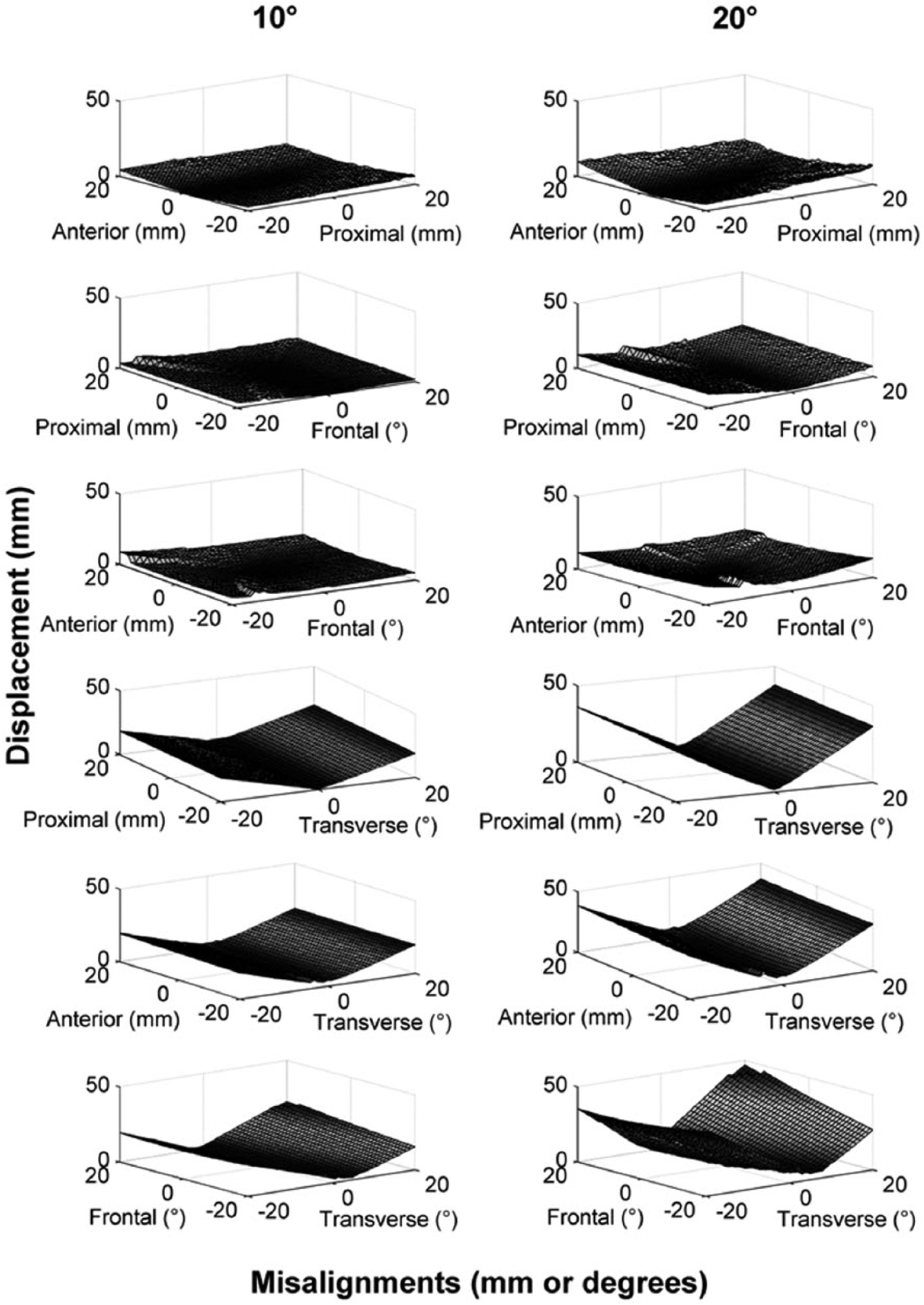
Surface plots showing the magnitude of relative displacement between corresponding tracking points on the leg and AFO resulting from misalignments of the AFO joint in anterior–posterior and proximal–distal directions (measured in millimeter), as well as in the frontal and transverse planes (measured in degrees). The left column shows displacements caused by misalignments when the ankle is in 10° dorsiflexion, and the right column shows displacements caused by misalignments when the ankle is in 20° dorsiflexion.
The resulting displacement (in mm) from the different binary combinations of the extreme misalignments at 20° dorsiflexion.
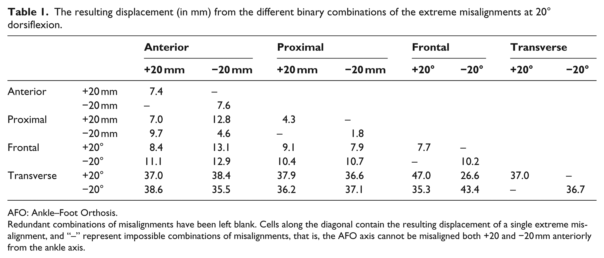
AFO: Ankle–Foot Orthosis.
Redundant combinations of misalignments have been left blank. Cells along the diagonal contain the resulting displacement of a single extreme misalignment, and “–” represent impossible combinations of misalignments, that is, the AFO axis cannot be misaligned both +20 and −20 mm anteriorly from the ankle axis.
Discussion
The results of the simulation strongly suggest that misalignments in the transverse plane lead to the most relative motion between the AFO and lower leg followed by misalignments in the frontal plane. This corresponds clinically to considering the effect of tibial torsion on ankle axis orientation, which was done using alignment tools and measurements when fabricating metal AFOs and should coincide with the location of the malleoli when fabricating polymer AFOs. The resulting difference in trajectories between the AFO and lower leg can lead to large pressures and shear forces on the skin, which in turn may lead to tissue damage. The discrepancies between the trajectories would also lead to large internal forces within the foot and the AFO. The results of the model suggest that, where possible, orthotists should prioritize transverse plane alignment. However, flexure joints would likely be more tolerant of misalignments, and in future, mechanical ankle joints may be designed that better track the anatomical axis, obviating the need for prioritization in the alignment process.
Rapid transitions within some of the surfaces, such as the sharp folds within the anterior–frontal and proximal–frontal surfaces seen in Figure 2, likely occur when a misalignment causes a sudden increase in the number of engaged springs within the model. The design of the AFO and the distribution of different stiffnesses across the leg create discrete boundaries where the energy of the leg/AFO interface greatly increases once the AFO starts pressing into the leg within those boundaries and engaging the corresponding springs.
Care must be taken when interpreting the results of the model. First, the calculated displacement will vary with the position of the tracking point: tracking points closer to the ankle joint axis will have smaller displacements than tracking points farther away. Second, the ankle joint used within the model is an accepted static approximation of the dynamic physiological ankle axis,3,7 which will contribute some error to the predicted displacements. Also, an AFO will never realistically achieve the large displacements with respect to the leg shown by this model since those displacements result from the AFO moving inside the leg. While the model minimizes overlap between the leg and AFO, it does not entirely eliminate it. The AFO joint would likely bind before the maximum displacements predicted by this model were achieved, preventing further motion until forces within the AFO were relieved in some way. These impossible trajectories do not negate the value of the model. Rather, they serve as indicators for a given misalignment’s propensity to create deleterious effects. A misalignment that forces the trajectory of the AFO through the leg would likely create large forces between the AFO and leg that may cause damage to tissues, binding of the mechanical joints, wear to the AFO, and reduce gait efficiency.
The physically impossible trajectories were made possible within the model by assuming that the AFO was rigid, that the AFO swung freely about its joint axis, and that the AFO does not affect the kinematics of the leg. By introducing a finite stiffness to the AFO, the model would be less likely to force the AFO through the leg. It would also be able to account for internal forces within the AFO. These forces could be used to estimate friction within the AFO joint and indicate the degree of binding. Once binding reached a certain threshold, the model could assume that the joint was locked and stop the simulation, eliminating physically impossible trajectories from the model. Expanding the model in this way would help clarify the scale of the detrimental effects of misalignments and help determine a range of “acceptable” misalignments. However, introducing stiffness to the AFO would significantly increase the computation time of the simulation. Computational simplicity was a goal for this model so that it could be widely distributed and quickly installed and executed on home/office computers for educational purposes within the orthotics community. In light of this restriction, AFO stiffness was not examined within the current model. 6
The stiffnesses of the springs used in our model were arbitrary, which can lead to errors in predicting the precise behavior of the system. We have conducted some preliminary work 8 in applying biomimetic stiffnesses to the model by incorporating reported stiffness values of soft tissues over the bone and muscle of the lower limb. 9 We found that the modified model revealed the same trends as the original. 8 Furthermore, we used the new stiffnesses to estimate the forces and pressures acting on the limb and compared them to pressures reported to cause tissue damage. 10 This comparison suggested a range of harmful misalignments. 8 The results of the preliminary work are limited by the range of tissue stiffnesses used. Several regions of the leg likely have different stiffnesses than those incorporated into the model. More research is needed to derive these values. However, this initial work demonstrates how the model can be expanded to provide more clinically relevant information.
Previous 2D models that described the effect of axis misalignments on AFO and leg motion were not able to describe the interactions revealed by the 3D model. The fact that misalignments in the transverse plane had such a dominating effect on relative motion between the AFO and leg emphasizes the importance of including the third dimension when modeling gait and prioritizing accuracy of alignment in the transverse plane. More work defining leg tissue and AFO stiffnesses is needed to confirm and improve the predictions of the 3D model.
Key points
We use a 3D computational model to determine the relative motion that occurs between the AFO and leg when the AFO and ankle joint axes were misaligned in the sagittal, frontal, and transverse planes.
The predicted displacements of all binary combinations of misalignments from 20° dorsiflexion and 20° plantar flexion are presented.
The model predicted that misalignments in the transverse plane had a dominating effect on relative motion between the AFO and leg.
Footnotes
Acknowledgements
The authors wish to acknowledge Andrew Hansen, PhD, and Steven Gard, PhD, for review of the final manuscript.
Author contribution
All authors contributed equally in the preparation of this manuscript.
Declaration of conflicting interests
Ethics approval was not required as this study did not involve human subjects.
Funding
This research was funded by the National Institute on Disability and Rehabilitation Research (NIDRR) of the US Department of Education under Grant No. H133E080009 (Principal Investigators: Steven Gard and Stefania Fatone). The opinions contained in this publication are those of the grantee and do not necessarily reflect those of the Department of Education.