
Abstract
Background and aim:
Dynamic alignment of transtibial prostheses is generally performed based on visual interpretation of gait without the benefit of any kinetic analysis in the clinic. The aim of this technical note was to present and discuss the possibilities of assisting dynamic alignment of transtibial prostheses through visualization of socket reaction moments.
Technique:
Smart Pyramid™ (currently Europa™) was used to measure the socket reaction moments under various alignment conditions from an amputee with transtibial prosthesis. The socket reaction moments were plotted to visualize the effect of alignment changes on them, and they were clinically interpreted.
Discussion:
Socket reaction moments could complement information available to prosthetists to optimize prosthetic alignment. They could be used to reduce excessive loading on sensitive areas, to improve gait stability, or to communicate the outcome of dynamic alignment with the amputees. Further research is needed to identify the contribution of kinematics and kinetics for optimal alignment.
Clinical relevance
Dynamic alignment of transtibial prostheses is currently tuned subjectively based on prosthetists’ experiences and skills. Socket reaction moments may potentially provide objective information for prosthetists to align transtibial prostheses in the clinic.
Background and aim
The alignment of transtibial prostheses is the relationship between the socket and foot in space, and it is tuned through three stages: bench alignment, static alignment, and dynamic alignment.1–4 A number of studies investigated the effects of prosthetic alignment changes on amputees’ gait. 5 The bench alignment is established based on amputees’ residual limb requirement (e.g. magnitude of contractures of the knee), but it is adjusted on the bench of a laboratory without amputees wearing the prosthesis. The goal is to set the orientation of the prosthetic components in the middle of the anticipated range of adjustments for subsequent static and dynamic alignment. In static alignment, the components are adjusted while the amputee is wearing the prosthesis under static weight bearing. The goal is to deliver appropriate socket height and orientation so that the amputee can balance the body well while standing. The dynamic alignment is undertaken through iterative adjustments based on observation of the amputee’s gait and communication with the amputee about their perception of a smooth forward progression, mediolateral stability, and socket comfort. This process is repeated until the prosthetist and the amputee agree that there is no longer a detectable improvement to be gained. The goal is to maximize the dynamic balance of the amputee provided by the prosthesis, and the amputee’s comfort, while walking.
In current clinical practice, prosthetists greatly rely on their personal experiences and skills as well as amputee’s perception of comfort to perform dynamic alignment. However, there is published evidence that the acceptable range of the alignment varies among prosthetists, even in repeated attempts by the same prosthetist, 3 and amputee’s perception of alignment is not very reliable. 6 A quantitative measurement that is sensitive to prosthetic alignment would therefore be valuable as additional information for aligning prostheses. Socket reaction moments can be directly measured at the base of the prosthetic socket using a moment-logging component, and these moments are systematically affected by alignment changes in transtibial prostheses.7,8 They can be measured without a computerized three-dimensional motion analysis system and force plates. Therefore, direct moment measurement has potential as a prosthetic gait assessment tool of being accepted in the clinical setting. The aim of this technical note is to present and discuss the possibilities of assisting dynamic alignment of transtibial prostheses through visualization of the socket reaction moments.
Technique
Equipment
The socket reaction moments can be measured using an instrumented prosthetic pyramid adaptor: Smart Pyramid™ (currently known as Europa™) (Orthocare Innovations, Mountlake Terrace, WA, USA).8,9 Its height is 3.22 cm, while its mass is 0.14 kg. Strain gauges located inside the Smart Pyramid are used to measure the socket reaction moments in the sagittal and coronal planes. The sampling frequency of the Smart Pyramid is 100 Hz, and the collected data are sent to the computer wirelessly via Bluetooth. A root mean square error (RMSE) for the measured socket reaction moments by the Smart Pyramid was tested by applying a series of known moments. The RMSE was 2.08% in the sagittal plane and 2.80% in the coronal plane. 8 While Smart Pyramid measures moments in 2-axis, another commercial device (iPecs, Warren, MI, USA) measures them in 3-axis, including moments in the transverse plane. 10
Procedures
This is a retrospective study of our previous work. 8 The Smart Pyramid was attached to the existing transtibial prosthesis with Multiflex foot and ankle (Endolite, Miamisburg, OH, USA) of a 46-year-old unilateral amputee. His height was 1.85 m and body mass was 85 kg. His left leg was amputated due to trauma 6 years prior, and the length of the residual limb was 18 cm. The alignment of the prosthesis was initially adjusted based on the agreement between the prosthetist and the amputee. This alignment was defined as nominally aligned. Subsequently, the alignment of the prosthesis was randomly changed from the nominal alignment as described in a previous publication: 8 angle alignment changes of 2°, 4°, and 6° (flexion, extension, abduction, and adduction) via the Smart Pyramid and translation alignment changes of 5, 10, and 15 mm (anterior, posterior, lateral, and medial) via a sliding adaptor. Therefore, data were collected under 25 alignment conditions including the nominal alignment. The amputee was instructed to walk down a 10-m path at a self-selected walking speed immediately after each alignment adjustment. The socket reaction moments were measured at each alignment condition. This study was approved by the institutional review board governing the institution, and informed consent was obtained from the participant.
Visualization of the socket reaction moments and alignments
The socket reaction moments during stance were normalized to 100% of the stance in 1% increments, and the average of three steps in each alignment condition was plotted. To present the data clearly and concisely, the socket reaction moments measured only at nominal alignment, 6°, and 15 mm of malalignments are presented in Figures 1 and 2. The alignment between the socket and the foot (i.e. position of the foot relative to the socket) is described in the socket centric view in which the socket is fixed in space and the foot is moved.
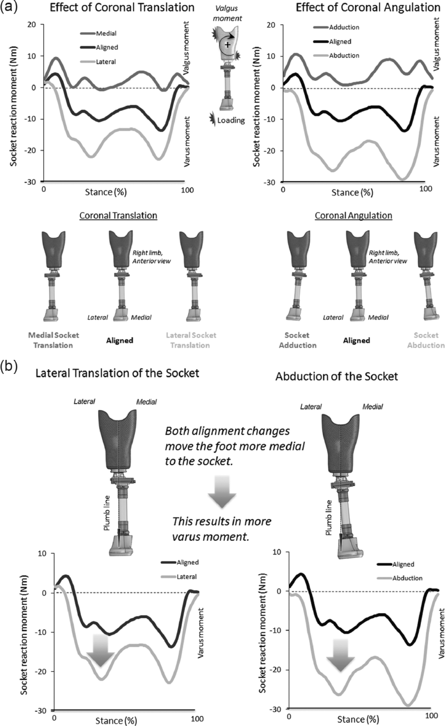
(a) Effect of the coronal alignment changes on the coronal socket reaction moments. Coronal translations present with 15 mm medial and lateral translations of the socket, while coronal angulations present with 6° adduction and abduction of the socket. Positive socket reaction moments are defined as external valgus moments, while negative socket reaction moments are defined as external varus moments. (b) Biomechanical explanation of the effect of the lateral translation and abduction of the socket on the coronal socket reaction moments.
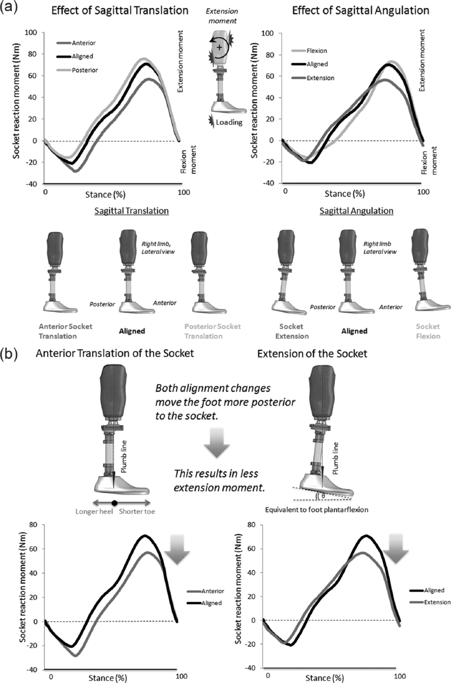
(a) Effect of the sagittal alignment changes on the sagittal socket reaction moments. Sagittal translations present with 15 mm anterior and posterior translations of the socket, while sagittal angulations present with 6° flexion and extension of the socket. Positive socket reaction moments are defined as external extension moments, while negative socket reaction moments are defined as external flexion moments. (b) Biomechanical explanation of the effect of the anterior translation and extension of the socket on the sagittal socket reaction moments.
Interpretation of the socket reaction moments
The effects of the coronal alignment changes on the coronal socket reaction moments are presented in Figure 1(a). When valgus moments are dominant, it is likely that loading is generally at the proximal–lateral and distal–medial aspects of the residual limb. Varus moments were dominant during stance under the nominally aligned condition. Lateral translation and abduction of the socket resulted in increases in varus moments. This may be because both alignment changes move the foot more medial to the socket (Figure 1(b)). This verifies the general clinical belief that slight inset of the foot in bench alignment results in more varus moments for stability during stance. 11
The effects of the sagittal alignment changes on the sagittal socket reaction moments are presented in Figure 2(a). When extension moments are dominant, it is likely that loading is generally at the proximal–anterior and distal–posterior aspects of the residual limb. Flexion moments in early stance were followed by extension moments throughout the rest of the stance under the nominally aligned condition. Anterior translation and extension of the socket resulted in decreased peak extension moment. This may be because both alignment changes move the foot more posterior to the socket, which results in a shorter toe lever (Figure 2(b)).
Discussion
This technical note presented a method to measure, visualize, and interpret the socket reaction moments under various alignment conditions collected from a transtibial amputee. In current clinical practice, dynamic alignment is generally performed by a prosthetist based on visual gait assessment and perception of the amputee about their gait. The goal of clinical prosthetic alignment is to optimize the prosthetic configuration based on a cost function of several factors, such as patient comfort, gait compensatory movements, socket-residual limb interface pressures, and metabolic cost, using the information available to the prosthetist. Smart Pyramid could contribute to this process of optimization because the socket reaction moments represent how a residual limb is loaded inside the socket and complement other information to achieve the desired alignment outcome.
Prosthetists could use the information from the socket reaction moments for various purposes in the alignment process. First, they could use them to prevent excessive loading on the sensitive areas of the residual limb. For instance, excessive flexion moments at early stance may indicate excessive loading on the distal end of tibia. This could be addressed by posterior socket translation or socket flexion (Figure 2(a)). Second, they could use them to improve gait stability. For instance, mediolateral stability can be generally achieved by adjusting the amount of varus moments during stance (Figure 1(a)). Third, they could use the socket reaction moments as a tool to communicate with their patients and visually explain the effect of alignment tuning and how that may potentially benefit them. This may help build more confidence about their prostheses.
There are some limitations associated with the alignment tuning process using Smart Pyramid. Performing dynamic alignment with the aid of kinetic information might reduce risk factors, such as excessive loading on the sound and residual limbs or dermatological issues for amputees while improving gait. However, kinetic and kinematic behavior is closely linked, and it may not be possible to manipulate one without modifying the other. Contribution of kinetics (socket reaction moments) and kinematics (visual observation of gait) for optimal prosthetic alignment requires further research. Each amputee may tolerate a different range of possible alignments, and some individuals may be able to compensate the effect of malalignments at the cost of greater and inappropriate loads on the residual limb and contralateral limb. However, it is challenging to take the level of tolerance into consideration when interpreting the socket reaction moments for dynamic alignment.
In conclusion, the socket reaction moments are responsive to alignment changes in transtibial prostheses, and they can be conveniently measured in the clinic. Further study is warranted to apply the socket reaction moments for assisting dynamic alignment of the transtibial prosthesis considering some limitations associated with Smart Pyramid.
Key points
Socket reaction moments can be measured directly on the transtibial prosthesis.
Socket reaction moments are responsive to alignment changes in the transtibial prostheses.
Socket reaction moments may provide valuable information to assist dynamic alignment of the transtibial prosthesis.
Footnotes
Author contribution
All authors contributed equally in the preparation of this manuscript.
Declaration of conflicting interests
None declared.
Funding
This study was supported by the National Center for Medical Rehabilitation Research, National Institutes of Health, Grant Numbers R43HD047119 and R44HD047119.