
Abstract
Background and aim:
Several studies have shown that feedback in upper-leg prostheses is possible, but slow or difficult to interpret. In this study, electrotactile and auditive error-based feedback, only giving feedback when an undesired event occurs, were tested for its use in upper-leg prosthesis when provided during a perturbation.
Technique:
A total of nine healthy subjects walked on a prosthetic simulator which was disturbed at the end of the swing phase. They received either no feedback, electrotactile feedback, or auditive feedback at the time of the perturbation.
Discussion:
The reaction time of the subjects only improved by 40 ms when using auditory feedback, compared to the no-feedback condition. No changes in reaction time were found in the electrotactile feedback condition. Considering perturbation detection was not taken into account in this study, this improvement is not enough for practical applications in upper-leg prosthesis.
Clinical relevance
Many transfemoral amputees are insecure about their prosthesis, are afraid of falling, or actually fall. Providing feedback specifically during a perturbation may prevent them from falling, or at least give them a chance to react.
Background and aim
Several studies have been performed on providing feedback about several states of a prosthesis to a user, but most of these studies showed that the feedback was difficult to interpret or reaction times were low.1–10 Continuous feedback, or feedback with information about the current state of the prosthesis, may therefore not be best suited for use in upper-leg prostheses. In this study, we therefore investigate a different approach of giving feedback: error-based feedback. This implies only giving feedback when an undesired event occurs. We hypothesized that if a subject only receives feedback in case of an undesired event they will react faster than without feedback. The outcome of the experiment was used to determine the usability of electrotactile and auditive error-based feedback in transfemoral prostheses.
Technique
Experiments
A total of nine non-amputees walked on a treadmill with a prosthetic simulator (PS) (Figure 1(a)), during which feedback was provided at the same time as a disturbance was applied to the PS. An informed consent was obtained before the experiments and the study was approved by the local Ethics Committee.
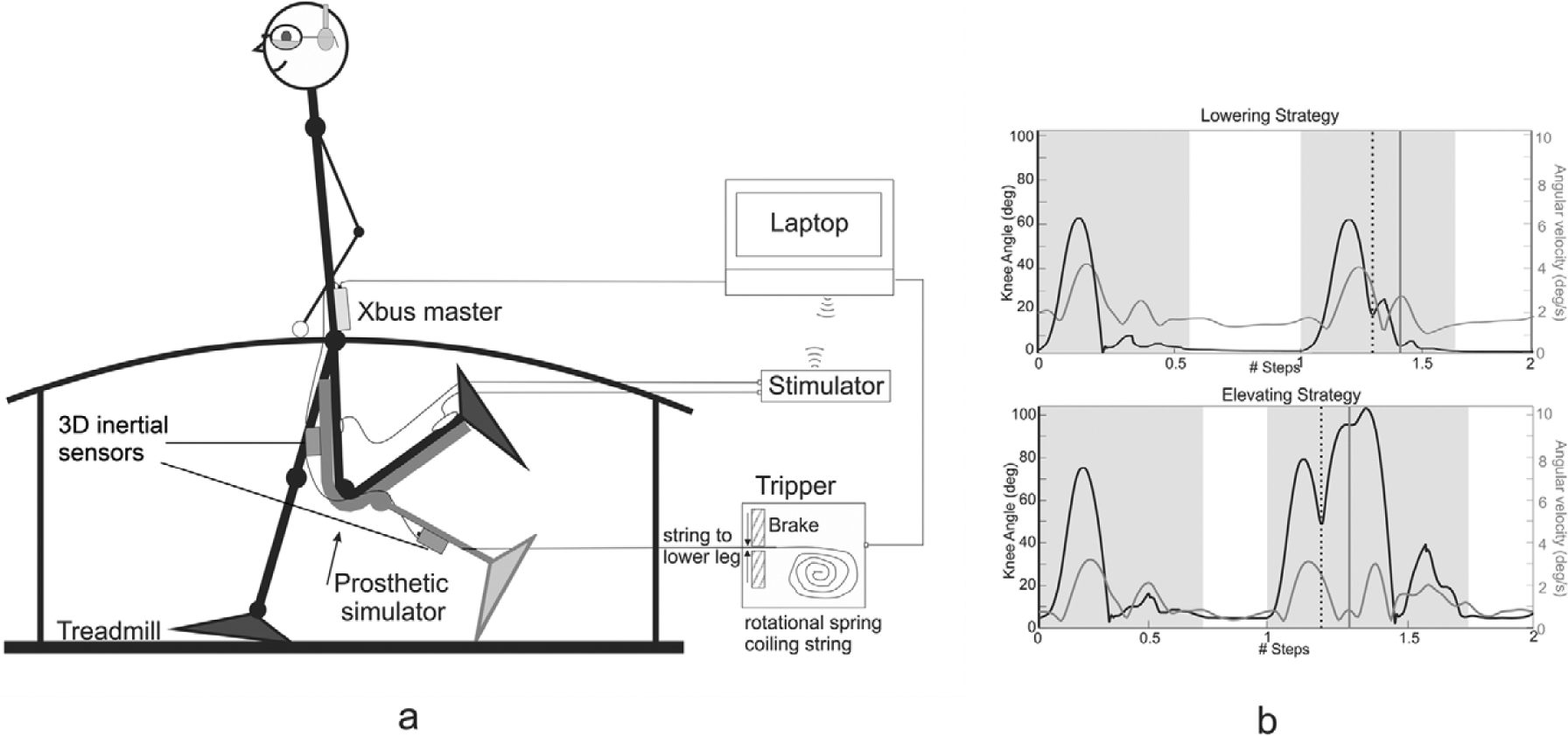
(a) Overview of the setup of the experiment. The prosthetic simulator is an L-shaped socket with a prosthetic knee, lower leg, and ankle fitted to it. This allows non-amputees to walk on a prosthetic knee. The upper and lower legs of this prosthetic simulator were each fitted with an inertial sensor, both attached to the Xbus master. The knee itself was fitted with a goniometer to measure the knee angle. The stimulation electrode was fitted to the back of the upper leg, and the contra electrode to the sound ankle at the same side. The Tripper device was attached to the prosthetic ankle. (b) Detection examples for the lowering strategy (top) and elevating strategy (bottom): in black, the knee angle from the precision potentiometer; in gray, the modulus of the angular velocity of the upper leg. Two steps are shown for each strategy: (1) a non-perturbed step (2) and a perturbed step. The shaded areas show the swing phase of the prosthetic leg, and the white areas show the stance phase. The black dotted line is the disturbance onset. The vertical gray line represents the detection of the first detectable change in the modulus of the upper-leg gyroscope data. A knee angle of 0° was considered an extended knee.
The experiments consisted of four phases. In the first phase, the subjects were allowed to learn to walk with the PS and determine their comfortable walking speed (1.5–1.8 km/h). The PS allowed healthy subjects to walk with a prosthetic knee; it was equipped with the single-axis knee 3R90 by Otto Bock.
Subjects were protected from falling with a harness and were allowed to use handrails, but this was discouraged. The second phase was used to determine the electrotactile stimulation settings prior to the feedback experiments.
The sensation and discomfort thresholds per subject were determined during walking on the PS. Both thresholds were determined using the 4-up/1-down method using an up/down step size of 0.28 mA.11,12 This allowed us to calculate the stimulus level. Stimulus level = (discomfort threshold − sensation threshold) × 0.8 + sensation threshold. Each stimulus during feedback trials consisted of 5 square cathodal pulses at the stimulus level.
The third phase consisted of the feedback experiments and the fourth phase consisted of a repetition of the second phase, but after the feedback experiments, to determine if the thresholds had changed.
In the third phase, four trials were performed per subject:
1. Without feedback (nFB1),
2./3. With auditory feedback (AF),
3./2. With electrotactile feedback (EF),
4. Without feedback (nFB2).
The AF and EF trials were randomized to prevent differences caused by learning.
Trials consisted of 400 steps, of which 20 were randomly disturbed with enough time in between the disturbances to recover and enough time to prevent them from being predictable. Between each trial there was a period of 5 min rest.
Setup
The general setup can be found in Figure 1(a). The PS was equipped with inertial sensors (Xsens, Enschede, The Netherlands) at the upper and lower leg (Figure 1(a)) and with a precision potentiometer at the knee, which was coupled to a device called Tripper. Tripper was the device used to provide the disturbances to the PS during walking. The device is attached by a string to the lower leg of the PS. The string always remained tight without interfering with the prosthetic swing phase, due to a spring inside the Tripper device, automatically coiling the rope as required (see Figure 1(a)). All devices were synchronized using a synchronization pulse seen in all data.
When the lower prosthetic leg was moving toward extension, Tripper was able to mechanically block the string and prevent further knee extension and thereby cause a disturbance to the subject. The prosthetic swing phase was elongated.
The potentiometer at the knee was used as an input for Tripper, to determine when the knee was moving to extension and when the disturbance could be applied. The disturbance was initiated when the knee was moving to extension at 95% of the maximum knee angle. Due to a time delay in the system, the disturbance was provided 50 ms later than when it was initiated, causing the actual disturbance to occur at the end of the swing phase. The string was blocked for 150 ms (see Figure 1(b)).
Feedback
AF was provided by Tripper itself due to the mechanical blocking of the string and therefore occurred at the time of the disturbance. To diminish the AF, subjects wore a headphone with (hard rock) music during the no-feedback and EF conditions, but not during the AF trials.
The electrotactile stimulation was provided by an electrotactile stimulator. 7 The stimulation electrode was placed at the back of the leg, above the knee in the PS. This was the only place where the PS would not interfere with the electrode. Subjects wore glasses that prevented visual feedback from the prosthesis.
Data analysis
Subjects were only able to actively control the upper leg. Therefore, the first reaction to the disturbance was expected to be seen in the above-knee inertial sensor data.
From the modulus of all three axes, the above-knee gyroscope data were determined in the first deviation in the disturbed gait cycle compared to the non-disturbed gait cycle. The time between this first deviation and the timing of the disturbance was calculated for each of the four conditions (see Figures 1(b) and 2(a)).
This first deviation in the above-knee inertial sensor data should lie at least 150 ms after the onset of the perturbation, because only after 150 ms the string was released. If a reaction is seen before the end of the perturbation, the subject would have had mechanical feedback of the disturbance itself. If this form of mechanical feedback exists, it should be clearly visible in the gyroscope data of the upper leg, as the leg would suddenly be pulled toward extension, while it is moving toward flexion.
Significant differences in the reaction time were tested using the Friedman and Wilcoxon signed-rank test (α = 0.05), with Bonferroni corrections where needed.
Results
Sensation thresholds
The sensation and discomfort thresholds were not significantly different before and after the experiment, therefore the effect of habituation was eliminated. 13
Reactions
Two “stumble” recovery strategies were found in the data, the lowering and the elevating strategy.14,15 Figure 1(b) shows an example for both recovery strategies. For both strategies a change in the gyroscope pattern of the upper leg was seen.
The top of the first peak in the modulus of the above-knee gyroscope data was taken as the first reaction. This is the point where for both strategies and for all subjects the first clear and detectable change in the gyroscope data was found. For all perturbations per feedback condition, the time between the perturbation onset and this peak was calculated. Examples of each can be found in Figure 2(a).
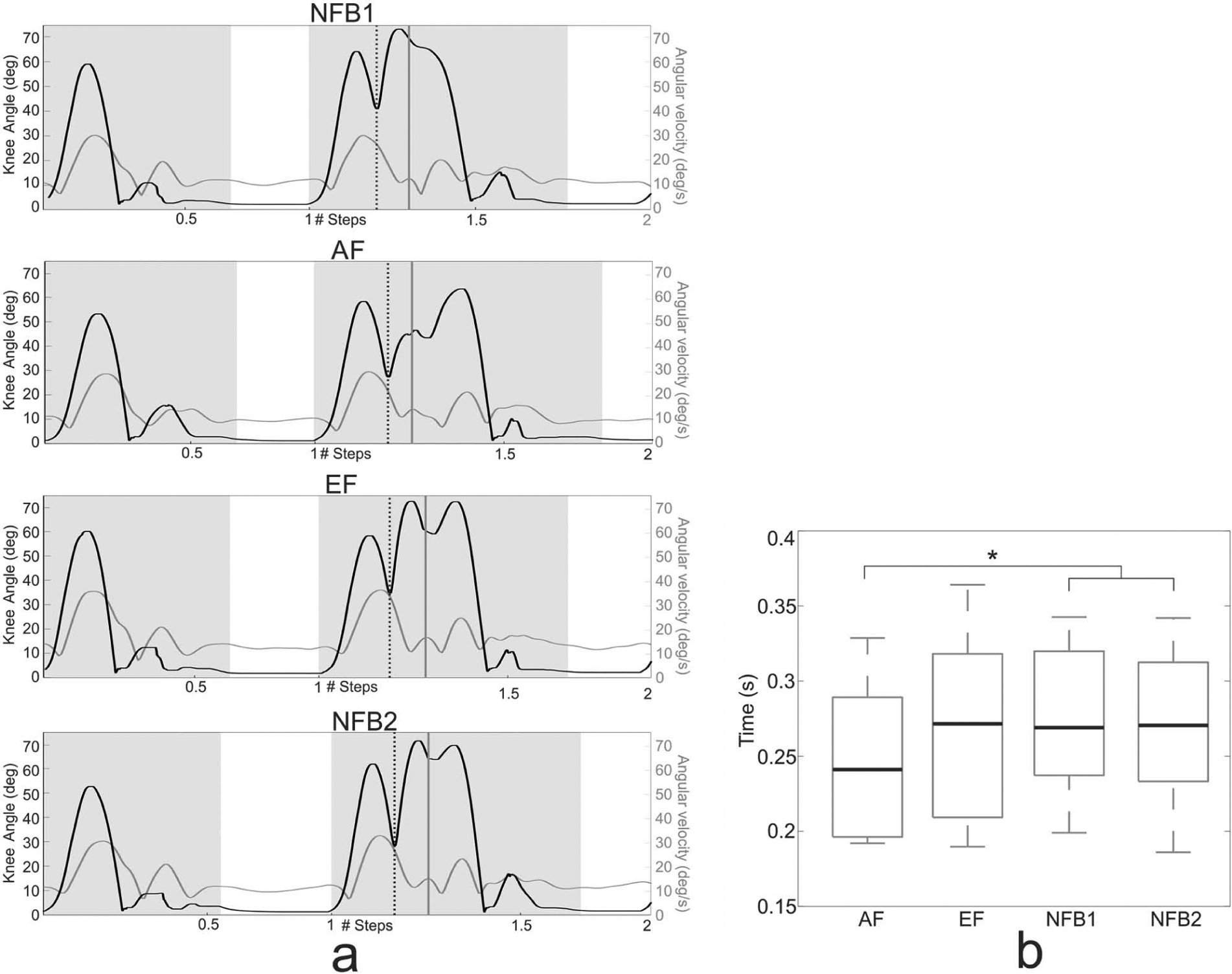
(a) Detection examples of the four different conditions, namely, no-feedback 1 (NFB1), auditory feedback (AF), electrotactile feedback (EF), and no-feedback 2 (NFB2): in black, the knee angle; in gray, the modulus of the upper-leg angular velocity. The vertical black dotted line is the disturbance onset, and the gray solid line is the first detected reaction of the subject. (b) Boxplot of the first changes detected in the upper-leg angular velocity for all subjects for all four experiments (AF, EF, NFB1, and NFB2). In each boxplot, the thick line represents the median; the box shows the 25 and 75 percentiles, and the whiskers mark the complete range; * indicates significant differences.
In recovery strategies, no change in the above-knee gyroscope data is seen until around 300 ms after the onset of the perturbation. This suggests that the perturbation did not cause any undesired mechanical feedback.
We determined per feedback condition, if the two strategies had significantly different timings, which was not the case. Subsequently we determined the differences between the feedback conditions, which can be seen in Figure 2(b). The median reaction times were 0.27 s of NFB1, 0.27 s of NFB2, 0.27 s of EF, and 0.24 s of AF. The only feedback condition that showed a significantly lower reaction time was AF (p = 0.05) by 30–40 ms.
Discussion
Reaction times to visual feedback are around 200 ms in specific experiments and we only found a reaction after 260–300 ms. For a reaction to a disturbance, this is rather long because a step only takes about 1 s. For the feedback to become useful, this time should have been reduced. For electrotactile (error-based) feedback to become a useful addition to above-knee prostheses, it should have shown an improvement in the reaction time in this study, which it did not. Even though it was presented to the subjects at the start of the perturbation, no differences were found.
Although AF did show a significant improvement, its usability remains questionable. A subject may not detect the feedback adequately in a crowded place or when distracted. The change in reaction time using AF was around 30–40 ms, but time delays for disturbance detection are around 50–70 ms. 16 The music in the non-auditory experiments could also have affected the reaction by the subjects, although this was not reported by the subjects and they were requested not to pay attention to the music.
The timing of the disturbance in this experiment coincides with a common disturbance in prosthetic walking. The disturbance leaves, however, little time for timely detection by the amputee. The disturbances in this experiment were enough to cause an actual stumble. Another option would be to elicit a reflex using electrotactile stimulation. This might allow faster reactions from the subjects, but little research was found on eliciting reflexes at the upper leg. Subjects were, however, allowed to use the handrail and a harness, which prevented them from falling. Therefore, the reduction in the number of stumbles was not an outcome measure. A real difference between the feedback conditions would have been a reduction in the number of stumbles. However, it is unlikely that this type of feedback will be of additional value to above-knee prosthesis.
Key Points
Feedback during undesired events was investigated for its use in upper-leg prostheses.
EF during a perturbation did not give better results than the no-feedback conditions.
AF during a perturbation reduces the reaction time, but not enough for it to become useful.
Footnotes
Conflict of interest
None declared.
Funding
This research is supported by the Dutch Technology Foundation STW, which is part of the Netherlands Organization for Scientific Research (NWO) and partly funded by the Ministry of Economic Affairs, Agriculture and Innovation, under grant no. 08003.