
Abstract
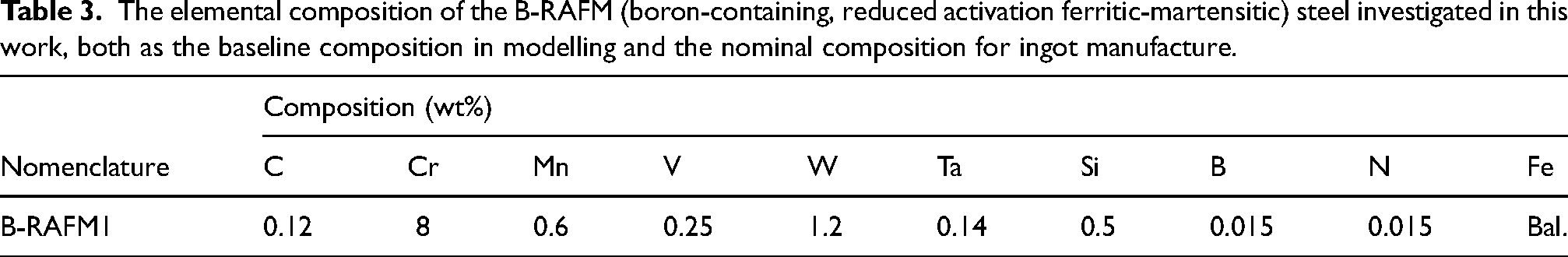
Steel will be an essential part of any commercial fusion reactor design. Applications in this area involve extreme conditions, imposing particular performance requirements, such as high operational temperature and creep resistance, and also a limitation on the elements that can be used due to the activation that occurs on interaction with irradiation. This work begins with a steel developed for conventional power plant applications, the IBN1 grade developed by IMPACT (a UK consortium of industrial and academic research organisations). This grade has shown excellent properties at high temperature due to high temperature-stable precipitate phases, but contains several elements that would become radiologically active to a degree that is incompatible with the required disposal routes after exposure to the fusion reactor environment. In this study, modifications of the composition are made to remove these elements, and thermodynamic modelling and experimental assessment of the phases that form are undertaken. In this, we have paid particular attention to the prediction of transformation temperatures (to understand if normalisation and tempering can be applied successfully) and the precipitates, to see if suitable phases that are likely to impart creep strength and other desirable properties would be formed. The modifications made include the removal of Nb, Mo, Ni, Co, Cu and Al from the starting alloy, and the substitution of Ta (intended to form carbides, replacing the effect of Nb). Modifications of the amount of retained elemental components, such as C, Mn and Cr, have been made with Thermo-Calc modelling, to ensure preservation of comparable phase transformation temperatures and microstructures. The predicted changes to the alloy are compared to the observations from experimental investigation, finding that tantalum can substitute for niobium in these systems and form similar carbides with similar distribution in the material, and that reduction of Cr to 8 wt% and increase of C to 0.12 wt% raises the Ae4 temperature to allow a high-temperature heat treatment without δ-ferrite formation. While assessment of the mechanical properties of this alloy would be required, the perspectives for these alloys to perform at high temperature that can be inferred from the microstructure are discussed.
Introduction
Reduced Activation Ferritic Martensitic (RAFM) steels have been developed to target applications in future nuclear fusion power plants.1–4 RAFM steels limit the amount of elements that cause long-lived radioactivity after operation in a fusion-spectrum neutron flux. Typical elements found in FM steels, such as Mo, Nb, Ni, Cu or N are limited or eliminated from the composition of RAFM steels in order for the expected radioactivity after service to decay to hands-on levels within 100 years.5,6 Most RAFM steels fall within the 7–9%Cr range, which in comparison to >9%Cr alloys, typically have increased creep strength, 7 reduced levels of hardening embrittlement, 8 and improved toughness. 9 At low temperatures (<350 °C), RAFM steels suffer a loss of ductility and embrittlement due to irradiation damage. 1 Operating conditions where the fracture-toughness can be severely reduced should be avoided (KIC ∼30 MPa.m1/2 is a reasonable assumed limit 10 ), thus limiting the steels to higher-temperature operating conditions where hardening-embrittlement does not occur. The temperature ceiling for RAFM steels is typically dictated by thermal creep, which limits the steels to ∼550 °C in order to operate the steel at 50–100MPa. 11 Considering typical design rules, this could require a creep rupture strength of up to 150 MPa for the intended component lifetime. There is increasing demand from fusion reactor design engineers for structural materials that can operate at temperatures in excess of 600 °C, particularly for thin-section components within the breeder blanket. Thus, developing higher-temperature RAFM steels could be important if fusion is to ever produce “useful” net power.
Ferritic-Martensitic (FM) steels for ultra-supercritical boiler pressure vessels are similarly limited by thermal creep. A class of FM steels with a much superior creep strength to the RAFM steels are the Martensitic Boron and Nitride-strengthened steels, or “MarBN” for short. Developed in Japan, 12 such steels can operate up to ∼650 °C in thick-section boiler components, allowing ultra supercritical power plants to be run more efficiently. The steels typically combine solid-solution strengthening elements – 1%Mo and 2.5–3%W – with precipitate strengthening from MX carbonitrides (NbC and V(C,N). Furthermore, the introduction of ∼3%Co helps to suppress delta-ferrite formation, refines both the Cr23C6 and MX precipitates, and also slows the coarsening kinetics of the carbides. 13 Boron addition (∼150 wt.ppm) enriches the Prior Austenite Grain (PAG) boundaries with boron on normalisation. 14 On tempering, the boron is transported to within the PAG and mostly ending up within chromium carbides as Cr23(C,B)6, which further slows the coarsening kinetics. This combination of tungsten, cobalt, and boron, and the large prior-austenite grain size (typically ∼100 µm, achieved through normalisation ∼1150–1200 °C), leads to an alloy with a vastly superior creep strength.
The UK “IMPACT” consortium has since developed a new steel of the MarBN class, designated as “IBN1” (Impact BN-1) and manufactured industrial-scale cast, forged and pipe products. 15 Long-term creep testing now shows substantial (>25 ⁰C) improvements in plant operating temperature capability compared with leading competitor martensitic steels. Our objective is to address the insufficient performance of current fusion reactor candidate materials through the transfer of this technology to fusion power. This will be done by adapting IBN1 to develop parallel boron-containing RAFM steels (B-RAFM steels), retaining the benefits of B-N control and improved heat treatment, while replacing high-activation elements such as niobium and cobalt with acceptable alternatives. In this contribution, we report the design of a new composition, supported by thermodynamic modelling, and the initial experimental assessment of the microstructure of the alloy formed.
Materials and methods
Thermodynamic modelling was performed using Thermo-Calc 2 software 16 and TCFE8: Steels/Fe-Alloys database v.8.2. 17
Casting took place at the University of Sheffield (Henry Royce Institute). An ingot of approximately 4 kg mass was produced, according to the composition specified in Table 1 (and here identified as B-RAFM1). This was cast in 70 × 80 mm cross section, producing an ingot of around 100 mm in height. Melt processing was by vacuum induction melting, with elements added either in elemental form, or as FeMn, FeB and CrN precursors (the latter encapsulated in a pure iron envelope), weighed to provide the desired compositions (due to volatility, some elements were deliberately added in increased quantity, for example Ta by 10%, FeMn by 15% and FeB by 10%). Compositional testing was carried out using ICP OES at Element Materials Testing, Sheffield. Sections of the ingot were taken in the as-cast form (initial thickness 65 mm), with the remainder hot rolled in order to refine the microstructure from the as-cast form. This was done in a series of sequential passes to ensure successful rolling, using a Fenn Model 081 hot reversing mill at the University of Sheffield. Rolling was done with the through-thickness direction being the 70 mm dimension of the original casting, and the longitudinal direction being the vertical direction in the casting. Samples were initially soaked at 1200 °C for 3 h, then received 10 passes at 5 mm reduction per pass (taking less than 2 min) before reheating at the soak temperature for 15 min. After this stage, a final 4 passes were used to achieve a final thickness of ∼13 mm. A rolling speed of 5mpm was used in all cases. Heat treatments were performed on samples taken from the alloys in a resistance heated tube furnace, with the tube sealed in order to provide a flowing argon atmosphere. Normalisation was at 1200 °C for 2 h, followed by rapid removal from the furnace (done manually using tongs) and air cooling to below 100 °C, with the samples positioned across the gap between two furnace bricks, in order to provide the most uniform cooling possible. Samples were then tempered at 735 °C for 16 h, with air cooling, with the heat treatments performed using the same furnace and methodology as normalisation.
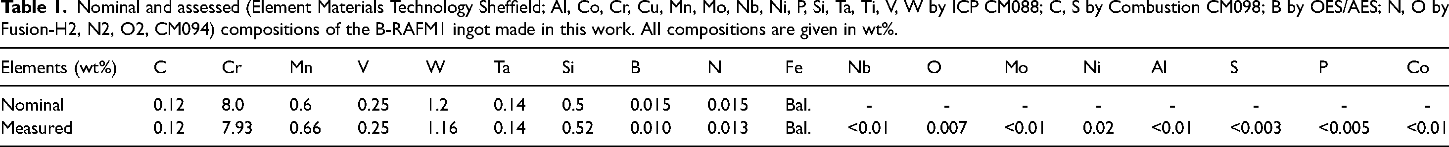
Nominal and assessed (Element Materials Technology Sheffield; Al, Co, Cr, Cu, Mn, Mo, Nb, Ni, P, Si, Ta, Ti, V, W by ICP CM088; C, S by Combustion CM098; B by OES/AES; N, O by Fusion-H2, N2, O2, CM094) compositions of the B-RAFM1 ingot made in this work. All compositions are given in wt%.
Samples were sectioned transversely, mounted ground and polished for optical microscopy, and indentation used to determine the HV5 in a 3 × 3 grid of hardness measurements, avoiding the outermost ≈ 2–3 mm where subsurface oxidation effects might have affected the data, but otherwise spanning the specimen surface area (spaced at least 5 mm apart), and thus collecting information from the centre, top, bottom and edges of the specimen (though not near the extreme edges of the specimen).
Specimens for electron microscope investigation were prepared by standard metallographic methods, grinding from P400 to P1200 grit, and polishing to 0.04 µm colloidal silica. Scanning electron microscopy (SEM) in both secondary electron (SE) and backscattered electron (BSE) modes was performed using an FEI Inspect F50 microscope, with energy dispersive spectroscopy (EDS) analysis performed using Oxford Instruments Aztec software. The area of the EDS point scan is 1 sq. μm, hence it is appropriate to note here that only precipitates and features of interest of approximately at least this size were analysed via this technique.
Transmission Electron Microscopy (TEM) was carried out on thin foil specimens, prepared by mechanical thinning to below 100 μm before electropolishing using a Tenupol-5 twin-jet electro polisher at −35 °C using a 5% perchloric acid, 35% 2-butoxyethanol, 60% methanol polishing solution. STEM-EDS mapping and point analysis were carried out on a JEOL JEM-F200 transmission electron microscope operated at 200 kV. Electron energy loss spectroscopy (EELS) was carried out with a GATAN quantum GIF using a 5 mm aperture and 150 mm camera length.
Dilatometry was performed on samples (6 × 6 × 24 mm) in the as-cast condition, in order to determine transition temperatures Ac1, Ac3 and Ms for comparison with predictions. Ac4 (δ-ferrite) was not determined experimentally in this work. The dilatometer used was the Netzsch DIL402 Expedis. A heating rate of 50 °C min−1 was applied from room temperature to 600 °C, thereafter 6.6 °C min−1 was used up to 1000 °C. The samples were then air cooled back to room temperature.
Compositional modelling and alloy design
Verification with IBN1
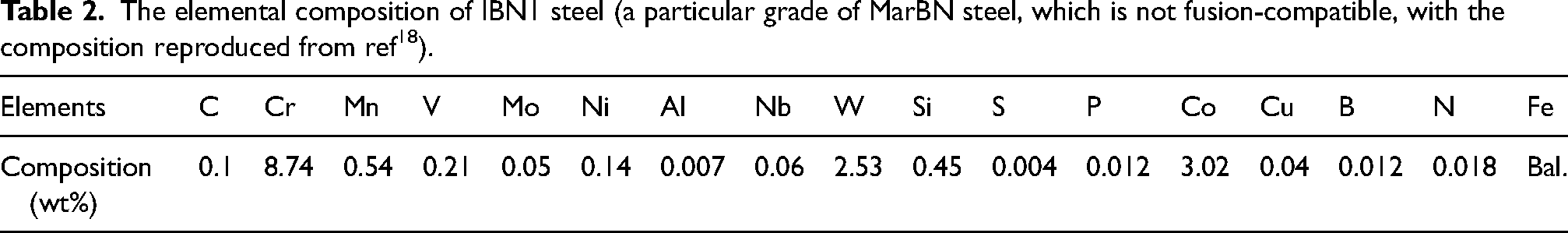
Although IBN1 is not suitably for reduced activation for fusion use, in order to gain confidence in the modelling and to understand parameters that could be more challenging, modelling of IBN1 as a known alloy was performed. The typical composition of IBN1 18 was used with Thermo-Calc 2023a software 16 and the TCFE8 database.
The produced variation in equilibrium phase fraction with temperature is shown in Figure 1, which can be compared with the same results from Figure 11 of Ref. 18 Both predictions are seen to be in agreement, with the same phases and transitions, and the same cardinal transformation temperatures identified. For example, the results agree that δ-ferrite should not form below 1300 °C, and that M23C6 carbides will be stable below 900 °C. Laves phase is predicted in both cases to start to form above 750 °C, and to make up a mass fraction of 3–4 wt% of the material by 500 °C. There is also agreement in the complex variation in the predicted content of NbC, which occurs as this is affected by, in turn the appearance of VN, and then M6C carbides on cooling. Initially P and S were included in our calculation, however, this caused the formation of additional precipitates (MnS and M3P) and formation of liquid to be lower than the previous calculations. 18 Removing P and S from the calculation (in the manner of simplifications often done in thermodynamic modelling) resulted in replication of the results, and such elements are excluded from the calculations used here, making them less complex and more time efficient.
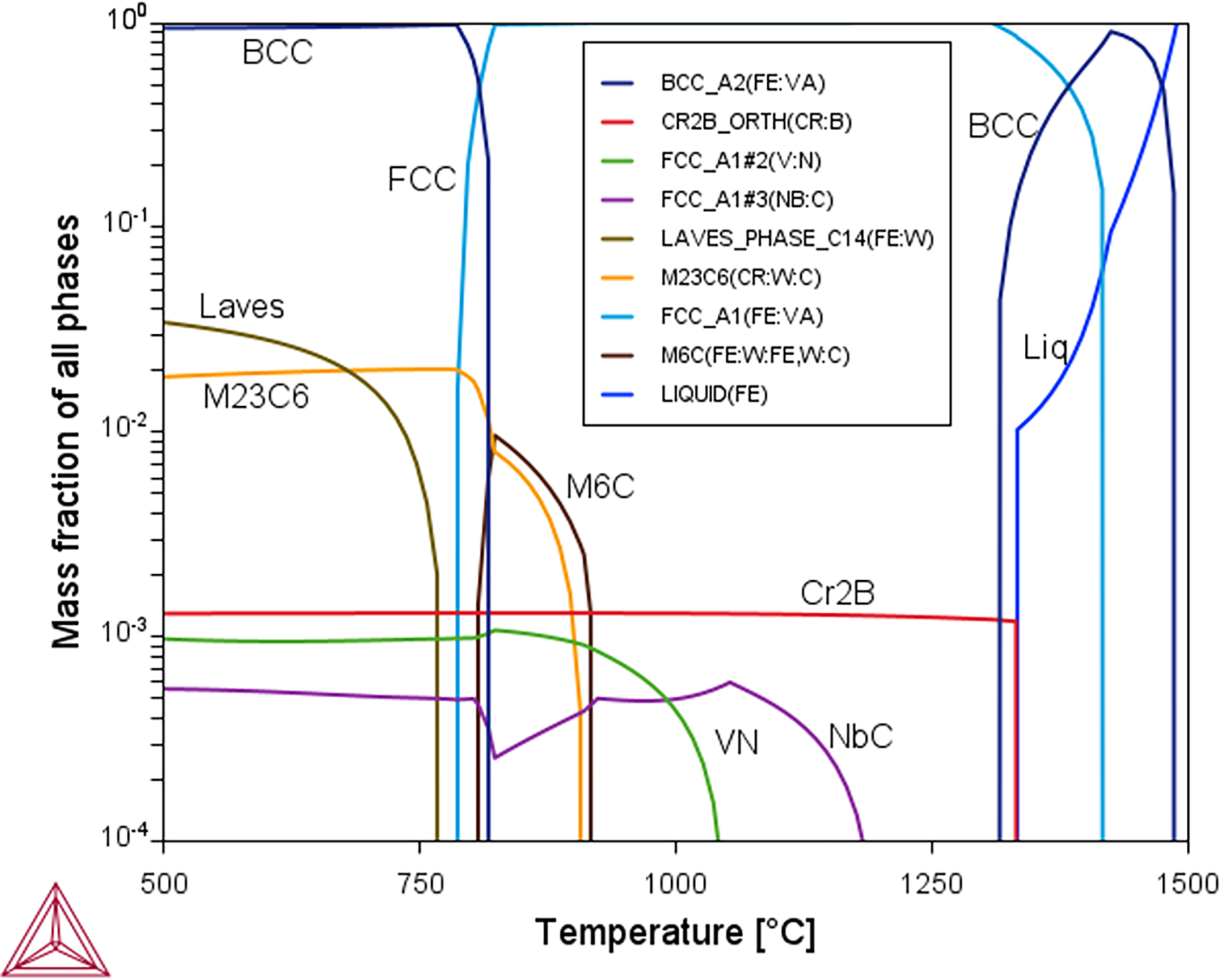
The equilibrium phase fraction with different temperatures for the IBN1 composition (composition given in Table 2), predicted by Thermo-Calc 2 software with the TCFE8 database.
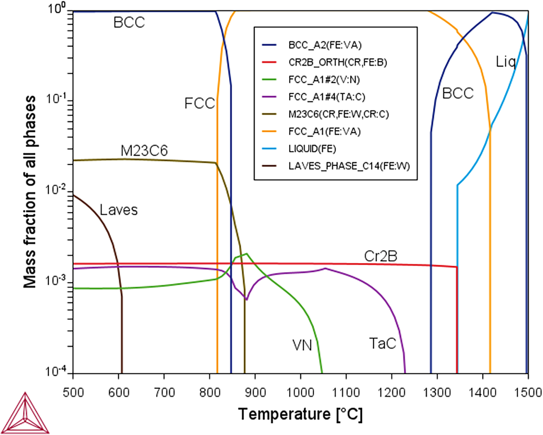
The equilibrium phase fraction with temperature for the B-RAFM1 composition (composition given in Table 3) predicted by Thermo-Calc 2 software with the TCFE8 database.
The elemental composition of IBN1 steel (a particular grade of MarBN steel, which is not fusion-compatible, with the composition reproduced from ref 18 ).
Reduced activation version of IBN1
The aim of the design process was to adapt the IBN composition (Table 2) into a form where the content of each element was limited to levels that would be acceptable for activation. Based on these limits, the content of Nb, Mo, Ni, Co, Cu, and Al were removed. The changes induced require compositional changes in order to attempt to retain what were expected to be desirable precipitates and microstructures. A key part of this is replacing the niobium with an alternative element that can produce carbides to retain creep strength. A candidate for this is tantalum which occupies the same group in the periodic table as niobium, but offers a suitably low level of activation, so the likely efficacy of this element was to be explored. In order to make use of the same approach as is effective for IBN, having an alloy that can be normalised at high temperature (1200 °C) without the risk of delta ferrite formation is also important as this allows the elements to be fully taken into solution, to be re-precipitated during tempering. The changes in elements are likely to lead to a reduction of the austenite-ferrite transformation temperature, so to avoid this, and the transformation to delta ferrite, the Cr, Mn and C contents can be adjusted, with the goal of keeping Ae1 and Ae3 above 800 °C (for postweld heat treatment), and Ae4 above 1200 °C. Exploration of an appropriate balance between austenite and ferrite formers under the new constraints was also important for this reason.
As an initial baseline, around which to vary the content of the elements of interest, a starting composition was selected, denoted B-RAFM1 (Table 3). This was loosely based on the nominal composition for Eurofer97, with boron added with the aim to replicate the delayed tertiary creep that has been observed for the MarBN alloys. 19 In this, the selection is following the concepts behind the IBN1 steel discussed previously, while respecting the limitations on activity of the elements that can be included. Boron can be problematic in steels targeting nuclear applications, due to B10(n,α) reactions. 20 However, this stage of the alloy design was agnostic to such irradiation effects, where simply creating microstructures that could theoretically improve thermal creep was the primary objective. In order to understand the nature of the B-RAFM1 composition and the differences the changes have on the key properties, it was modelled by Thermo-Calc to produce the expected content of different phases at equilibrium at different temperatures (Figure 2) and the key transformation and precipitate dissolution temperatures that were identified from this (Table 4).
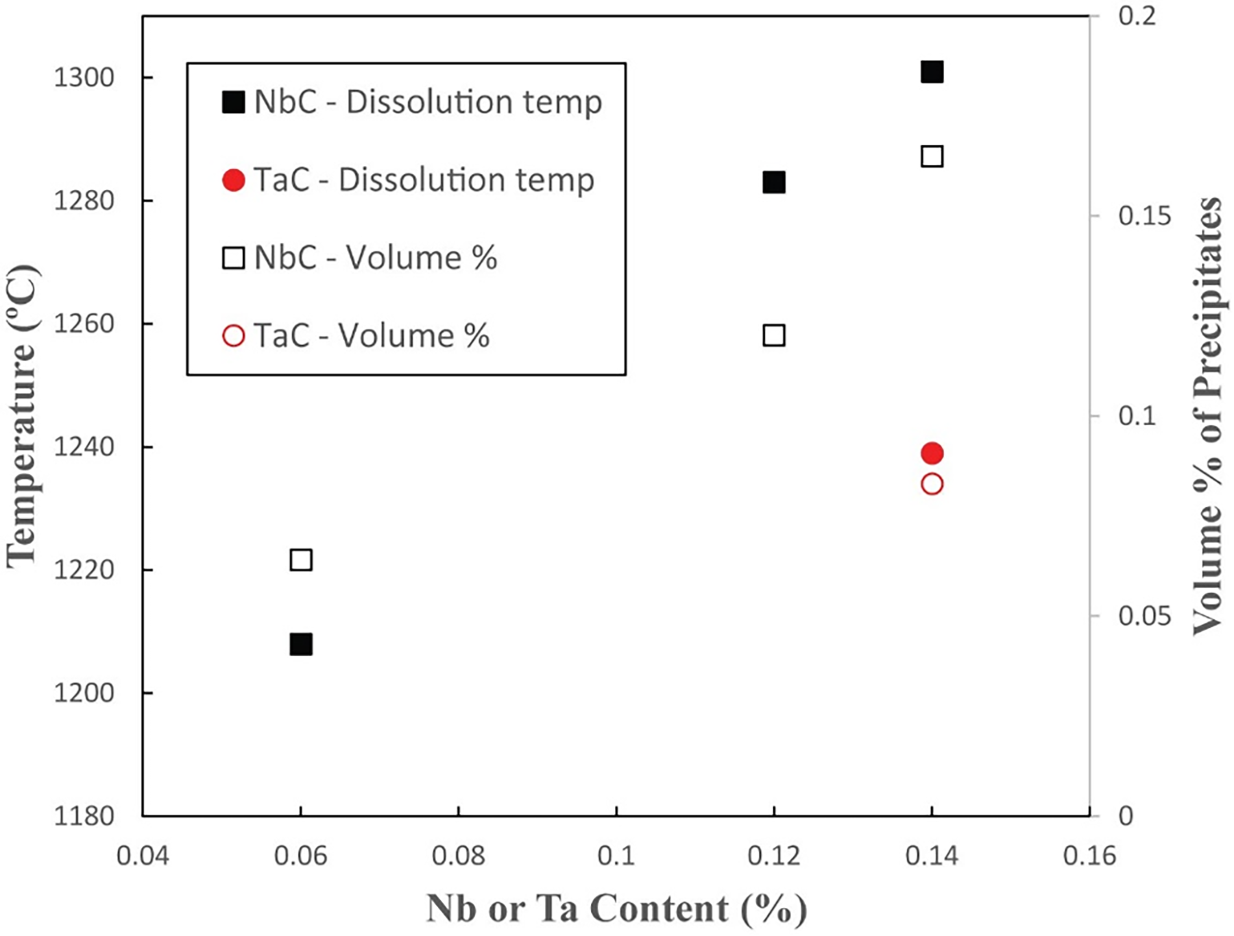
The variation in equilibrium dissolution temperatures and volume fraction of NbC with Nb content predicted by Thermo-Calc 2 software with the TCFE8 database for the steel compositions in Table 5. The predicted values for TaC with the baseline B-RAFM1 composition are also shown.
The elemental composition of the B-RAFM (boron-containing, reduced activation ferritic-martensitic) steel investigated in this work, both as the baseline composition in modelling and the nominal composition for ingot manufacture.
The key equilibrium phase transformation temperatures and the precipitate dissolution temperatures predicted by Thermo-Calc 2 software with the TCFE8 database for B-RAFM1 steel compared with IBN1 steel are examined in this work. All temperatures in °C.
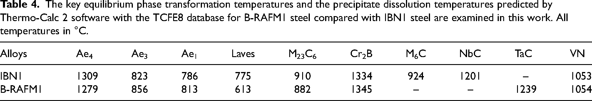
These predictions show that the B-RAFM1 steel composition has slightly higher phase transformation temperatures than IBN1 steel. With regard to the precipitates, the M6C is not predicted to form in B-RAFM1 steel, due to the lower content of Cr compared to IBN1 steel, which contributes significantly to this phase. The dissolution temperature of M23C6 decreased by nearly 30 °C to 882 °C in B-RAFM1 steel. With a higher content of B and V in B-RAFM1, the dissolution temperatures of Cr2B and VN precipitates are increased over those in IBN1 steel. The Ta in B-RAFM1 is intended to fulfil a similar role to Nb in IBN1, and it is notable that the TaC phase is more stable with a higher dissolution temperature than NbC. The baseline B-RAFM1 steel therefore has higher phase transformation temperatures and also slightly increased maximum precipitate dissolution temperature to 1345 °C, compared to IBN1 steel.
There is also some unexpected behaviour observed between approximately 825 °C and 1050 °C for the VN and TaC phases (Figure 2). In this region, the phase designated TaC is destabilised, and the volume fraction of the phase designated VN increases. In this region, the composition of the designated VN phase changes, increasing significantly in C and Ta, suggesting formation of a single (V,Ta:C,N) FCC phase. This result suggests some uncertainty within the thermodynamic database, relating to the competing stability of TaC and VN for different compositions.
Comparison of the effect of Ta with Nb
In the newly designed B-RAFM steels, Ta is added instead of Nb, due to the reduced activation requirements. One of the important roles of this addition is to form stable carbides, and this behaviour can be checked, both with regard to the carbide dissolution temperatures and volume fraction of precipitates. Variants of the baseline B-RAFM1 composition were created with the Ta removed and different amounts of Nb added, 0.06 wt%, 0.12 wt% and 0.14 wt% (Table 5; Nb-containing variants are given a designation indicating the presence of this element). The lower end of the range is selected to be comparable to the addition present in IBN1, while the upper end is the same amount as the Ta that is added in B-RAFM1. The equilibrium dissolution temperatures and maximum percentage volume of TaC and NbC present at any temperature (as a general characteristic of their presence) were calculated by Thermo-Calc, following the procedures outlined earlier.
Compositions modelled to explore the effect on precipitates of Ta compared to Nb in B-RAFM steels. Modelled dissolution temperatures (in °C) of selected precipitates (TaC and NbC) for each composition are also shown.
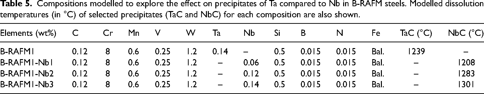
The predicted equilibrium dissolution temperatures for TaC and NbC are also shown in Table 5 and are plotted in Figure 3. Adding 0.14 wt% Ta in B-RAFM1 gives a TaC dissolution temperature of 1239 °C, which is higher than the NbC dissolution temperature (1208 °C) with Nb at 0.06 wt%. The volume fraction of TaC is also slightly higher than NbC under these conditions. By interpolation on the graph, when increasing the Nb to around 0.1 wt%, the NbC dissolution temperature would be increased to be similar to TaC when the Ta content is at 0.14 wt%, with a similar volume fraction of NbC. With further increase in the Nb content to the same amount as Ta, the NbC dissolution temperature increased to 1301 °C, higher than TaC in the B-RAFM1 baseline, with higher volume fraction. This shows that Nb has a higher capability than Ta to react with C, but, with the increased amount of Ta in the B-RAFM1 specification compared to the Nb that would be used in IBN1, the carbides produced have comparable stability and volume fraction. It would therefore be expected that the B-RAFM1 Ta content of 0.14 wt% would be suitable to satisfy the requirement we have set of producing precipitates that are likely to be suitable for high-temperature service.
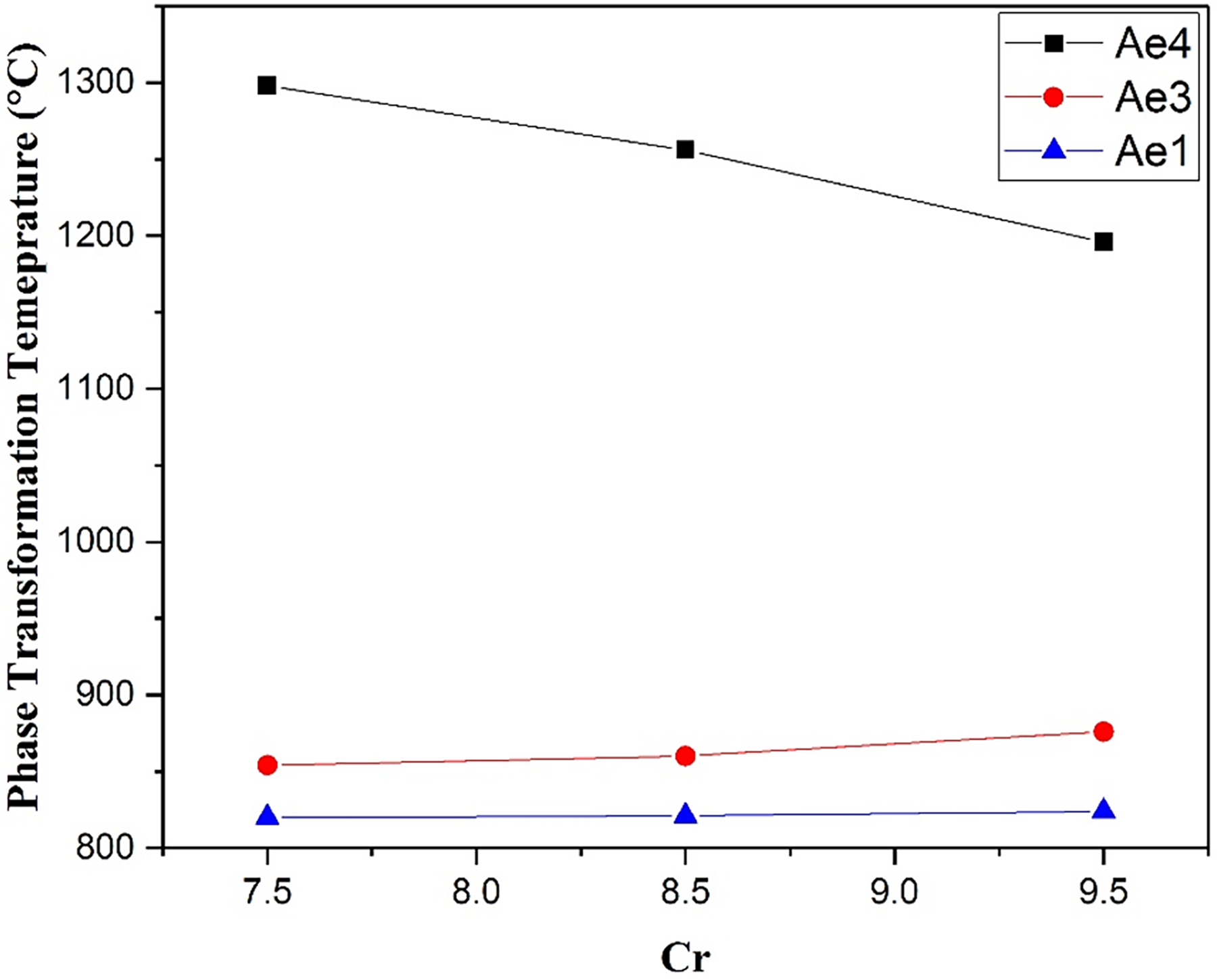
The variation in equilibrium transformation temperatures with Cr content predicted by Thermo-Calc 2 software with the TCFE8 database for the steel compositions in Table 7 .
Variation of Cr content
Chromium is a ferrite stabilizer, and therefore its level may be a means to control the transformation temperatures. Chromium will have other effects, and is considered to be important for creep-fatigue performance and oxidation resistance, so variations in this element were explored over the range 7.5 wt% to 9.5 wt%, taking the B-RAFM1 composition and varying the amount of Cr as specified in Table 6 (Cr-containing variants are given a designation indicating the presence of this element). The equilibrium phase transformation temperatures for these alloys were predicted by Thermo-Calc as described previously.
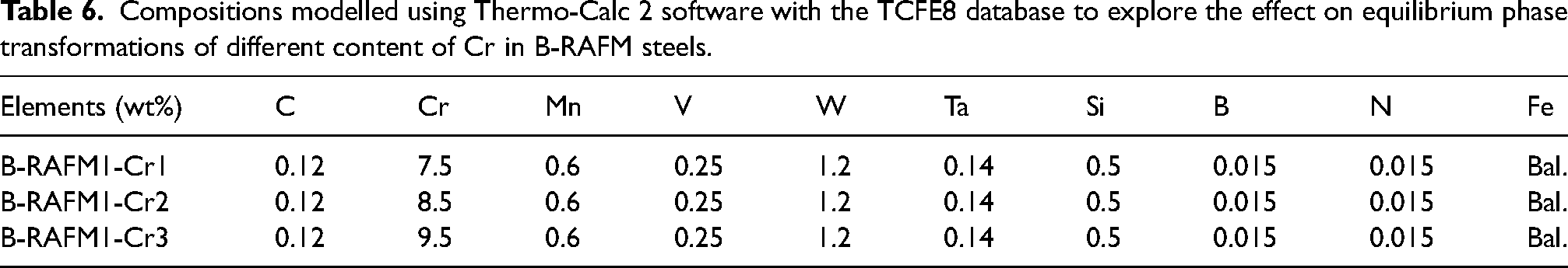
Compositions modelled using Thermo-Calc 2 software with the TCFE8 database to explore the effect on equilibrium phase transformations of different content of Cr in B-RAFM steels.
The predicted equilibrium phase transformation temperatures are presented in Figure 4. From the calculated data, the Ae4 temperature is predicted to be decreased and the Ae3 temperature increased with increasing Cr content, with the effect on Ae4 in particular being relatively strong over the range explored. Considering the requirement that Ae4 is higher than 1200 °C and that Ae3 should be higher than 800 °C, the figure suggests that a good compromise for content of Cr would be 8 wt%, which is adopted as the level of Cr for the baseline B-RAFM1.
The variation in equilibrium transformation temperatures with Cr content predicted by Thermo-Calc 2 software with the TCFE8 database for the steel compositions in Table 7.
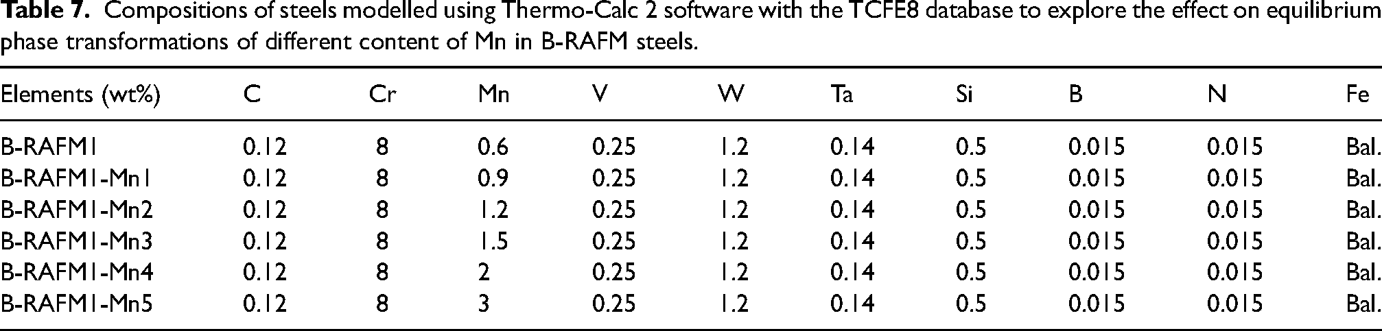
Compositions of steels modelled using Thermo-Calc 2 software with the TCFE8 database to explore the effect on equilibrium phase transformations of different content of Mn in B-RAFM steels.
The martensite start temperature is also important to consider, and this will be affected by the Cr level (lower levels of Cr will increase the Ms temperature). The change can be estimated by the empirical equation
21
below: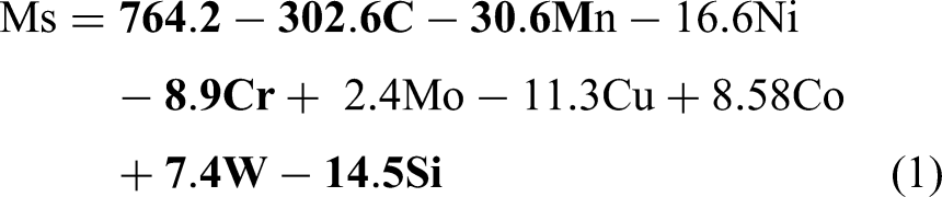
The parts of the equation relevant to the current compositions are highlighted in bold. Using this equation for the compositional range explored here suggests that Ms will vary between 626 °C and 644 °C. The Ms of the composition selected (B-RAFM1 baseline) with 8 wt% Cr is 640 °C.
Variation of Mn content
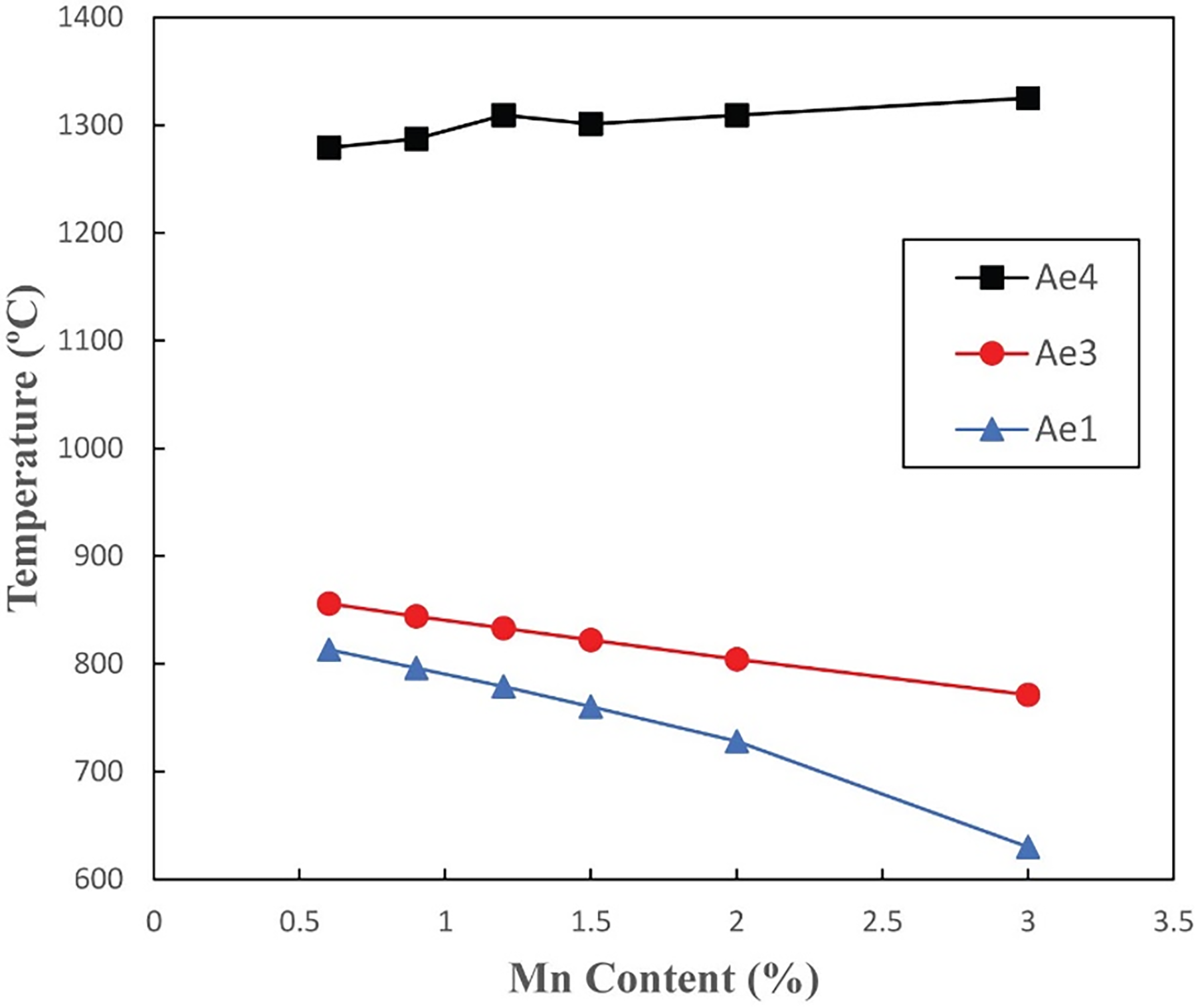
Manganese is another element that could act to alter the transformation temperatures, and its content could be increased (while remaining acceptable from an activation point of view) to try to stabilise the austenite phase to higher temperatures. The effect of Mn on the predicted equilibrium phase transformation temperatures has been assessed using the compositions shown in Table 7 (alloys with different Mn content are indicated with their nomenclature), where Mn content is varied between 0.6 and 3 wt%. These compositions were modelled using Thermo-Calc as previously.
The predicted equilibrium phase transformation temperatures are shown in Figure 5. The results demonstrate that with increasing Mn content, the Ae4 temperature increases only slightly, but the Ae3 is reduced rapidly. For the whole Mn composition range explored, the Ae4 temperatures are all higher than 1200 °C, but are not further increased. However, when the Mn content is higher than 1.2 wt%, the Ae1 temperature is reduced to lower than 800 °C. Mn also has a role in improving the hardenability, strengthening, and hot workability, which motivates the addition of 0.6 wt% in the B-RAFM1 baseline, but there is little evidence from this exploration that a benefit can be gained from increasing it further.
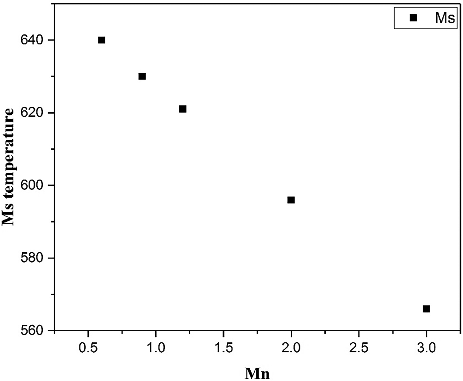
The variation in martensite start temperature with Mn content was predicted by means of the empirical equation (1) for the steel compositions in Table 7.
Mn can also affect the martensite start temperature, and this effect can also be estimated for the compositions using the same equation as previously. The results of this are shown in Figure 6, illustrating how increasing content of Mn lowers the martensite start temperature. Taking the effects of Mn together, there seems little motivation to change if from the level of the baseline alloy (0.6wt%), but the amount could be increased up to around 1.2wt% without it being likely to lead to negative effects.
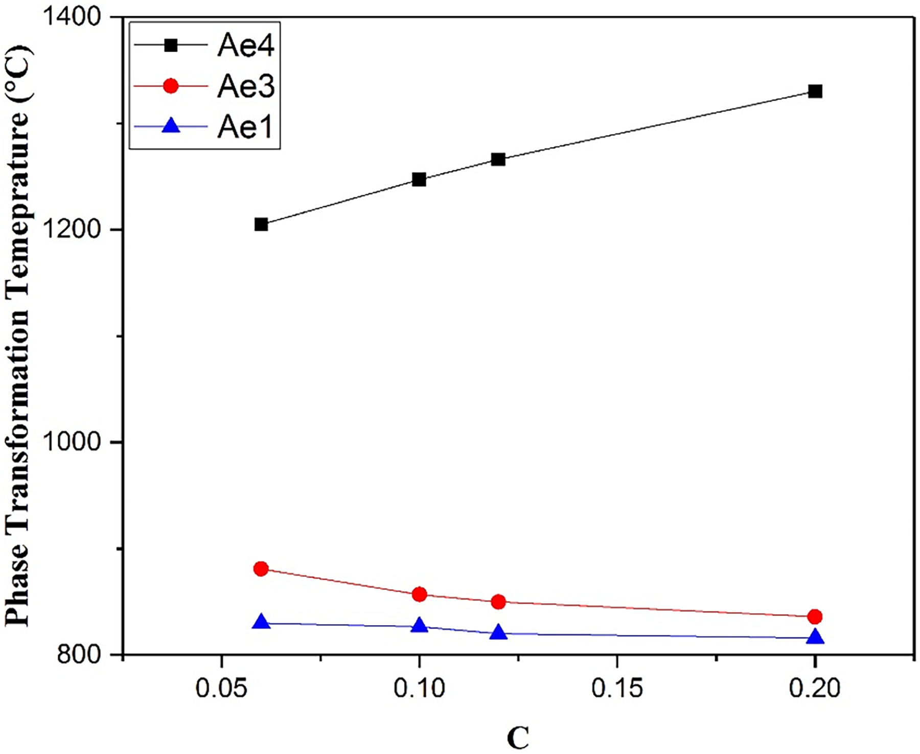
The variation in equilibrium transformation temperatures with C content was predicted by Thermo-Calc 2 software with the TCFE8 database for the steel compositions in Table 8.
Variation of C content
Carbon is also an austenite stabilising element, and the effect of this on transformation temperatures has been explored. The B-RAFM1 baseline was taken and adjusted to have different contents of C, Table 8 (alloys with changed compositions are given and appropriate designation). The equilibrium phase transformation temperatures have been simulated by Thermo-Calc, following the method detailed previously, and the results are shown in Figure 7.
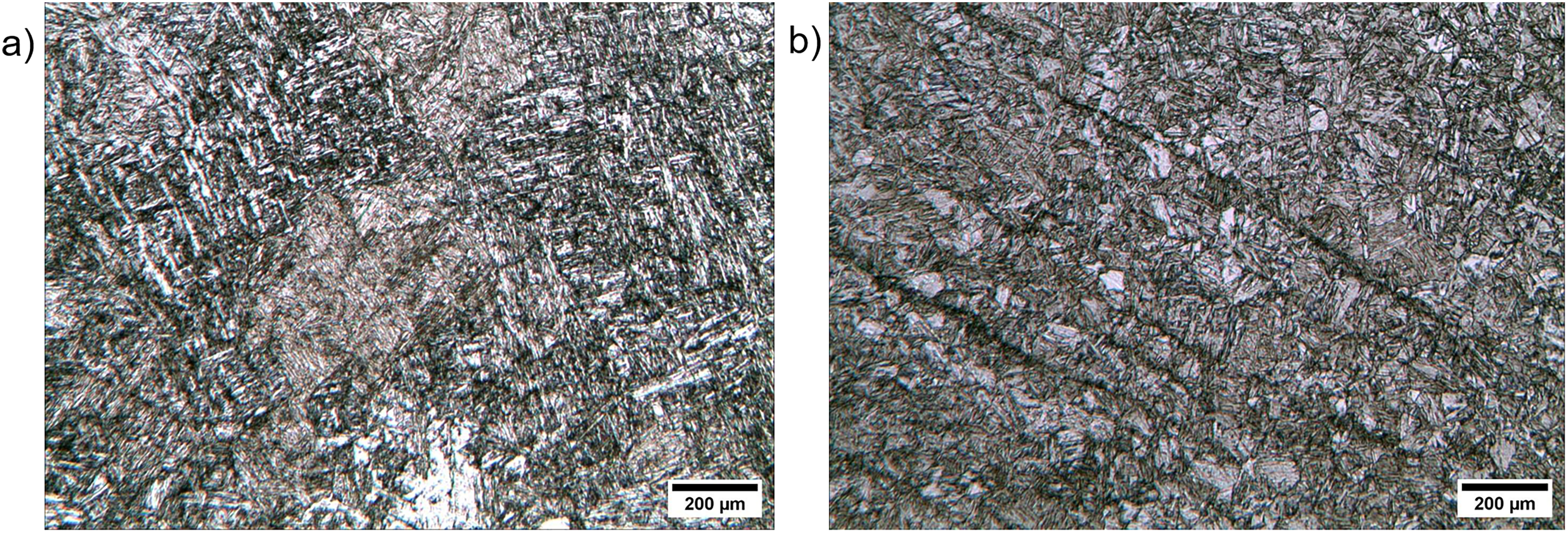
Typical microstructures (obtained by optical microscopy) of the heat treated experimental sample of B-RAFM1 produced in this work, showing two different conditions: (a) as-cast and heat treated condition, (b) rolled and heat treated condition. In both cases the heat treatment applied was normalisation at 1200 °C for 2 h, and tempering at 735 °C for 16 h, under argon.
Compositions modelled by Thermo-Calc 2 software with the TCFE8 database to explore the effect on equilibrium phase transformations of the content of C in B-RAFM steels.
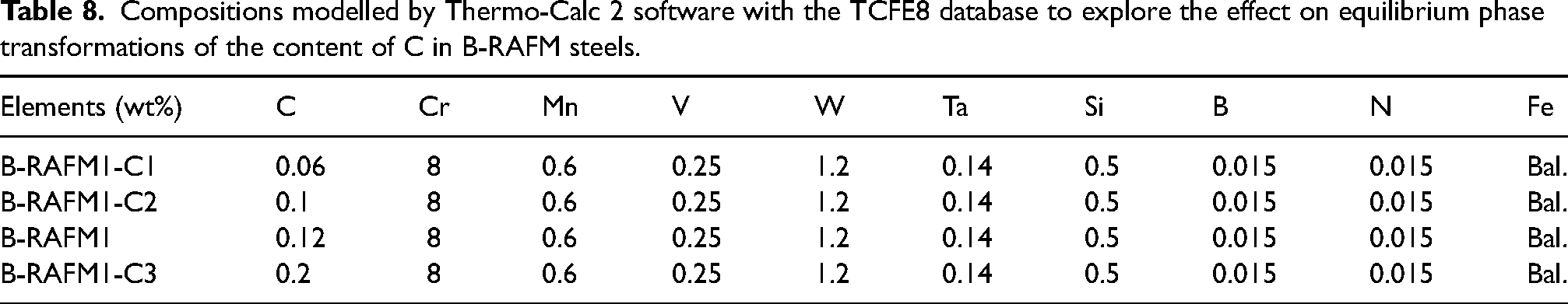
The data illustrate that with increasing C content, the Ae4 temperature is increased, and the Ae3 temperature is decreased, trends which are similar to the effect of Mn, though with greater magnitude. When increasing the C content to 0.2 wt%, the Ae1 remains higher than 800 °C but Ae4 is predicted to increase higher than 1250 °C (however, such a high carbon addition would induce poor welding performance). To meet the requirement for austenite to ferrite phase transformation temperature higher than 800 °C, and delta ferrite phase transformation temperature higher than 1200 °C, while keeping the C content low, the B-RAFM1 baseline level of 0.12 wt% is predicted to be an appropriate level for this element.
Carbon content will also clearly affect the Ms temperature; using the same equation as earlier suggests that the variation will be between 616 °C and 658 °C for the range explored here, with the Ms temperature of the IBN1 composition being predicted to be 640 °C using the empirical equation (1).
Selected composition
Overall, considering the variations on the composition explored using Thermo-Calc 2 software with the TCFE8 database, no advantages have been indicated over the B-RAFM1 composition (summarised in Table 4). This suggests that this would be a suitable selection for further development, and this was selected for experimental manufacture and exploration.
Experimental results and discussion
Following the Thermo-Calc modelling, an ingot of the B-RAFM1 composition was made, as described in the methods section. This ingot was to be experimentally characterised, in order to provide data to validate the modelling results. The compositional analysis of the ingot after manufacture yielded the results shown in Table 1 (which also gives the nominal composition). This composition is assessed as being within a suitable specification, such that this experimental alloy is appropriate to examine to validate the modelling results.
Microstructures
After heat treatment (starting from both the as-cast and rolled conditions, in order to examine the effect of the deformation) the samples all showed wholly or largely lath martensite microstructures. Typical as-cast and rolled microstructures are shown in Figure 8 (note that there could be some ferrite presence, which may be what is seen as a light phase at the bottom of Figure 8(a)). These rolled materials show deformation banding along the rolling direction, seen in the images as a dark banding. This feature results from heavy deformation and fragmentation of the lath structure.
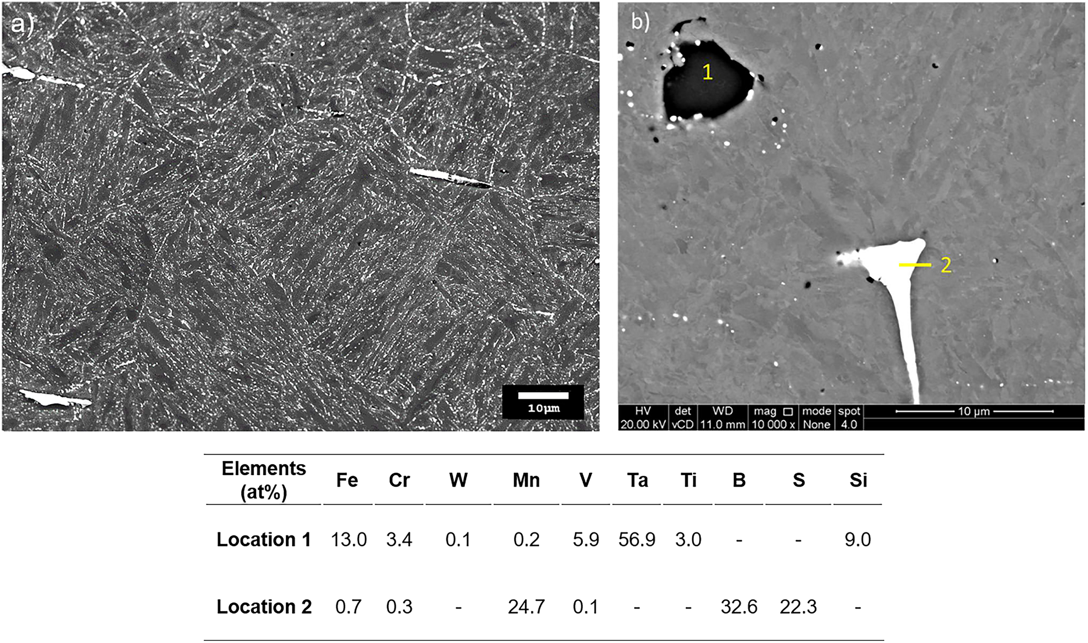
Typical Scanning Electron Microscope (SEM) images microstructures seen in B-RAFM1 under the of the rolled and heat treated condition, showing: (a) general view and (b) detailed view of some example larger inclusions, which were occasionally observed. In the case of the image shown, these include a possible Ta-rich phase (1) and a MnS inclusion (2). The table included shows the quantified EDS analysis (based on the average of 3 scans at each point) of the composition at points 1 and 2.
These final microstructures are affected by the structure when in the austenite phase. The prior austenite grain size was measured on the as-cast samples using the mean linear intercept (MLI) method. 22 The number of prior austenite grain boundaries (PAGBs) intercepting at least three arbitrarily drawn scan lines of length ≈ 10–20 mm was counted, and the mean grain size dimension thereby calculated, yielding a result of 302 ± 51 µm. This value may be somewhat approximate, as it may be that not all PAGBs were clearly visible in the optical microscope. There was also some, albeit fairly slight, evidence of grain anisotropy in the rolled samples, which would be expected following the deformation received by the material in the austenite phase. Broadly, however, the results provide reasonable semi-quantitative data on grain size.
Vickers hardness HV5 was measured over a 3 × 3 grid of hardness measurements. This found a value of 257 ± 4 HV5. Industrial IBN1 MARBN normalised at 1200 ⁰C (for 16 h, rather than the 2 h used here) and tempered at 735 ⁰C 16 h has a typical hardness of the order of 260–280HV5, 15 so the hardness value (and grain size) of the material heat treated from the as-cast condition are broadly in line with these. While, due to the multiple factors that contribute to strength this is not conclusive, it does suggest that tantalum substitutes effectively for niobium, achieving comparable hardness levels. Further, this could be taken as potentially indicative of comparable creep strength levels (although no creep tests have yet been conducted on this material).
Next, the material in the rolled and then heat treated condition was examined. IBN1 is typically considered in the as-cast form, so there is less data available to compare with the rolled product explored here. In the rolled samples, the prior austenite grain sizes were assessed as being substantially smaller, 78–114 µm (although notably this is still an order of magnitude higher than might be expected of EUROFER 97), suggesting that rolling may produce persistent microstructural features that constrain grain growth during normalising, in a way that does not happen for the as-cast material. A candidate for such a structure could be the extensive deformation banding seen. Some PAGBs were observed to cross these deformation bands, but many do not, such that the deformation band spacing (around 100 µm) sets an upper limit to the grain size. The hardness for rolled and heat treated material is 262 ± 3 HV5, only marginally higher than the as-cast material, despite the smaller grain size. This suggests that the contribution to the strength of this smaller grain size is not that large, and that the precipitate structure is rather the main contributor to strength in this alloy, although further analysis to verify this would be required.
Precipitates
In order to determine that, in the B-RAFM1 alloy with tantalum, the precipitates are indeed present as expected, and that their distribution is similar to that found with niobium-containing alloys, microscopic examination was necessary. SEM was used to assess the microstructure; a typical SEM image, Figure 9, again shows the martensitic structure, with a grain size broadly consistent with that measured on the optical specimens. This indicates that to two different imaging modes in optical and electron microscopy are both able to reveal the microstructure properly. EDS analysis of the larger inclusions, Figure 9(b) and accompanying table, gives compositions which could correspond to an MnS phase, or possible boride, and regions of an undetermined precipitate type, but one that appears to be significantly enriched in tantalum. Note that these features exist at a different scale, and a different apparent composition as assessed by EDS, to the finer precipitates seen in the TEM investigation, discussed below. While these results show that such phases can be seen in the alloys, the number of instances of these phases observed is not sufficient to permit an analysis of their relative frequency, nor have sufficient regions been explored in detail to prove the absence of other precipitates in the sample. A comparison can be made with EUROFER97, based on the analysis by Fernandez et al. 23 In their SEM investigations, MnS, oxides and Ta-rich inclusions were found. The presence of large deoxidation products such as sulphides and oxides which form directly from the melt is usual in steels, but the presence of Ta-rich precipitates in a similar size range is more noteworthy. The implication, taking our findings in conjunction with the literature observations on EUROFER 97, is that tantalum in RAFM steels may also be lost from solution into melt-precipitated large inclusions. If these large inclusions are oxides, then they will be stable to higher temperatures than the carbides, and this and their size would make them harder to dissolve on normalising. This would deplete the amount of tantalum available to be reprecipitated as potentially creep-strengthening fine-scale phases on tempering, reducing the total volume of such precipitates that was possible to achieve from a given tantalum addition to the alloy.
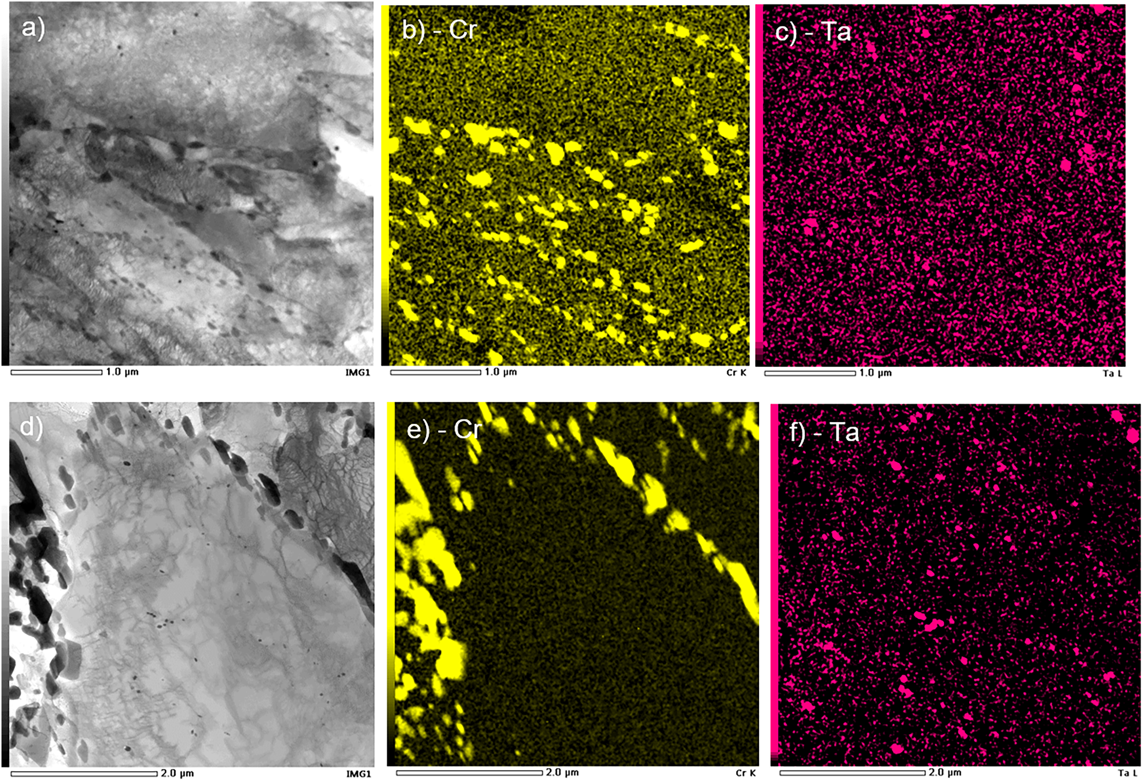
Example Transmission Electron Microscope (TEM) images (a, d) obtained from B-RAFM1 under the rolled and heat treated condition, along with quantitative Energy Dispersive X-ray Spectroscopy (EDS) maps of the distribution of Cr (b, e) and Ta (c, f) in the same areas.
Transmission Electron Microscopy was used to assess the formation of precipitates at a fine scale. Figure 10 shows TEM images of two different, randomly-selected regions, with corresponding EDS maps of the distribution of Cr and Ta across the same field of view. The images in the figure demonstrate that there are two carbide types with differing size and distribution. The two characteristic carbide types were; chromium-rich carbides, typically of ≈ 0.1–1 μm in diameter, which were primarily located on martensite lath boundaries and prior austenite grain boundaries, and tantalum-rich carbides, which were generally smaller, ≈ 0.1 μm diameter, and were located within martensite laths.
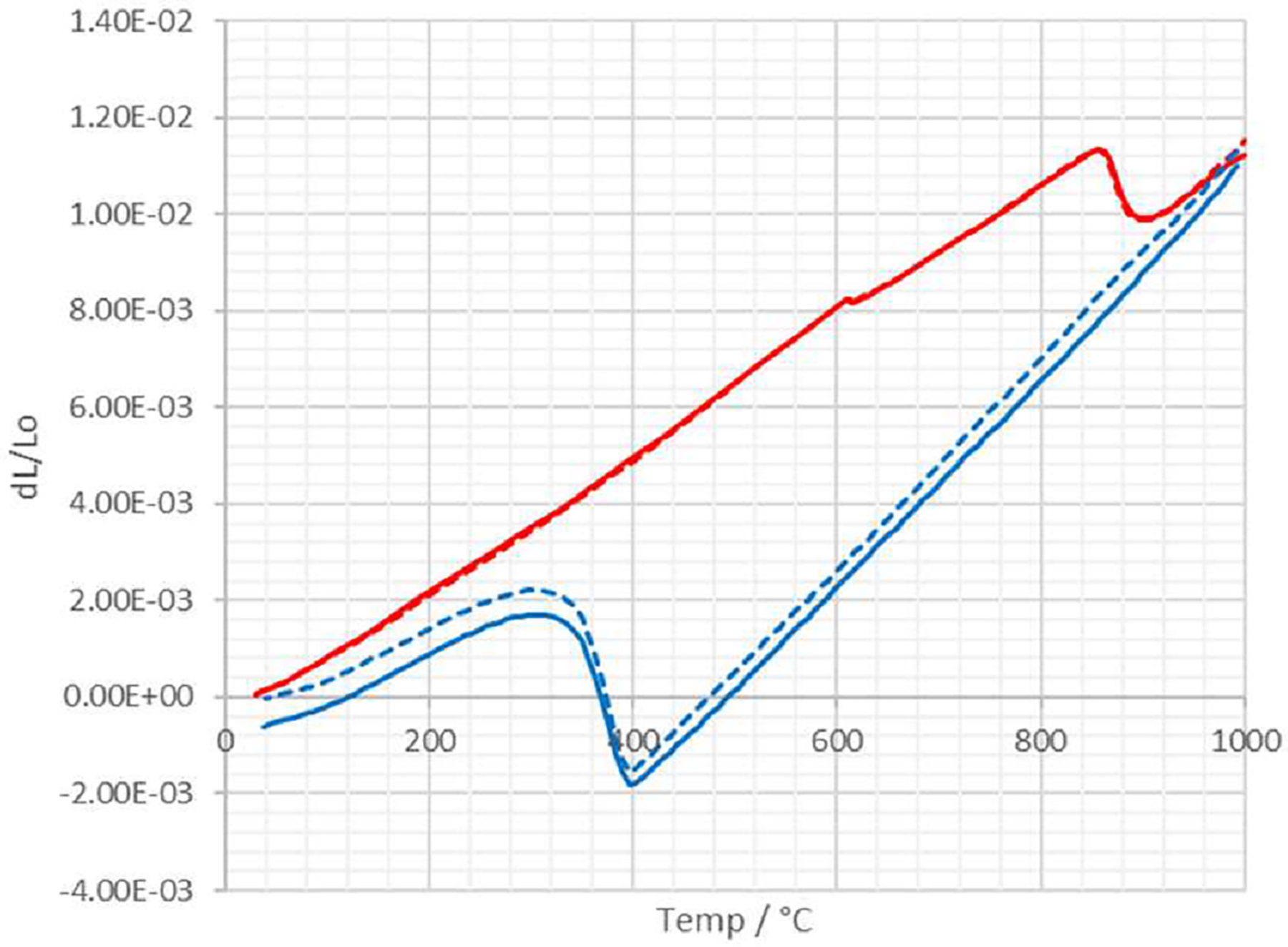
Heating (red) and cooling (blue) dilatometry curves from dilatometer experiments on two separate samples of a steel of the B-RAFM1 composition. One sample is shown with solid lines, the other with dashed lines; these do not signify any particular difference, with data from both samples included to illustrate the reproducibility.
In TEM investigation of EUROFER97, Fernandez et al. 23 also found two main types of sub-micron tempering precipitate; in that case they were chromium-rich precipitates and tantalum / vanadium-rich precipitates. These would appear to correspond broadly with the two main precipitate types observed here, the relatively large M23C6 carbides, primarily formed on the PAGBs, and the finer scale MX carbides / carbonitrides, mainly within grain interiors. However, it is of course important to assess how these precipitate types and distributions may vary between these different alloys.
In EUROFER97, the Cr-rich precipitates, identified as M23C6, were the main precipitates observed. They were ≈ 0.025–0.02 μm in size, located mainly along grain and lath boundaries, of varied shapes, and typically 66 at. % Cr and 31 at. % Fe with traces of W and/or V. The MX type precipitates were smaller, ≈ 0.008 to 0.04 μm, rich in Ta or V, and mainly located inside the subgrains. Three types of MX morphologies were identified after tempering: Type I (commonest) a spherical Ta or V rich MX, Type II a plate-shaped fine V-rich precipitate, and Type III a specific V-wing morphology formed by secondary V-rich precipitation on Ta-rich particles. EDS analyses showed a wide range of compositions, from 60–80 at. % Ta down to 15 at. % Ta, with V being the other main constituent alongside smaller percentages of Fe and Cr. Fernandez et al. did not fully identify these precipitates, but V is commonly recognised as a nitride former, while Ta is a carbide former. These results are therefore comparable to the findings here, which suggests that a very similar distribution of fine-scale precipitates forms in B-RAFM1 as in EUROFER 97, an unsurprising result given the similarities that exist between the two compositions. Further analysis would of course be needed to determine if any of the differences are significant, and to shed more detailed light on precipitate formation mechanisms.
Transformation temperatures
As well as the microstructure and the phases formed, another point of comparison between the Thermo-Calc predictions and the experimental alloy would be the temperatures at which phase transformations occur. Due to the volume change that accompanies many of the key phase transformations in steels, these temperatures can be assessed from dilatometry results, assessed over the temperature range of interest. Figure 11 shows two heating-cooling dilatometry curves, captured from repeat experiments on two samples of the alloy. The two curves on each plot show excellent agreement, and transformation temperatures can be inferred for each alloy from the points at which they deviate from linearity, with average values being Ac1 860 °C, Ac3 915 °C and Ms 399 °C. The measured Ac1 value is about 25–30 ⁰C higher than the predicted Ae1 value, and the measured Ac3 is some 80–90 ⁰C higher than the predicted Ae3 value. Differences in this direction of similar order are expected due to kinetic effects and are similar to those determined for MARBN steels by McLachlan. 24
Following the findings of the experimental study reported here, which demonstrate the basic concept behind a reduced activation composition for a MarBN alloy, there are further important analyses that would be required in order to assess the materials suitability or otherwise for applications in fusion. The most immediate of these would be creep testing. Bhattacharya 1 provides useful comparative data on competing RAFM alloys, showing that standard EUROFER 97 is inferior to Grade 91. Modified heat treatment can lead to considerable improvement, with short term data superior to Grade 92, but longer term data fall sharply. Data presented on a 3 W high B alloy are more impressive, with creep strength above that of Grade 92 out to ≈10,000 h. This may provide a benchmark for alloys such as those developed here, though noting that in the current case the tungsten level has been held to 1%, and this is likely to be a significant contributor to good creep performance. Along with such assessments of the behaviour of the B-RAFM1 alloy, further compositional modifications could be investigated experimentally, in order to widen the understanding of Reduced Activation Ferritic-Martensitic steels containing boron, and increase their potential to address some of the materials capability gaps for fusion energy.
Conclusions
This project undertook the rapid development and modelling exploration of a new candidate B-RAFM steel composition for use in a fusion reactor system. While a finalised composition was not targeted within the work, and assessments of key behaviours such as the mechanical response (including creep) and the resistance to irradiation would be a vital part of this, it is possible to draw some conclusions concerning alloys of this type, where the benefits of boron-containing steels are to be exploited in a fusion setting.
The Thermo-Calc simulation results displayed in Figure 3 and the microscope images in Figures 9 and 10 show that tantalum can substitute for niobium in these systems, in terms of the formation of similar carbides which are well distributed through the material. It is possible that some of the added tantalum is more easily lost to large oxides or other inclusions, but this could be addressed by optimisation of the processing. Also, importantly, while these carbides are similar in terms of their appearance in the microstructure, their efficacy in influencing mechanical properties would have to be confirmed experimentally.
These alloys have also used a slight reduction of chromium to 8 wt%, and an increase of C to 0.12 wt%. As shown by the Thermo-Calc simulation results in Figures 4 and 7, this raises the Ae4 temperature and allows the use of high normalising temperatures, and thus better hardness (and possibly creep strength). While the effect of this on other properties, such as environmental resistance and mechanical behaviour, is not known, this may suggest that reductions in the Cr levels typically used in RAFM steels is an effective means to allow these higher heat treatment temperatures, minimising the risk of delta ferrite formation. As with any such modification, the effect on other behaviours, such as the martensite start temperature, must also be borne in mind.
Footnotes
Acknowledgements
The authors would like to acknowledge funding for this work from UKAEA via the UKAEA / EPSRC Fusion Grant 2022/27 (EP/W006839/1), and from the Henry Royce Institute Materials Challenge Accelerator Programme (MCAP014), under UKRI funding (EP/X527257/1). We also wish to acknowledge the Henry Royce Institute for Advanced Materials, funded through EPSRC grants EP/R00661X/1, EP/S019367/1, EP/P02470X/1 and EP/P025285/1, for access to the Consarc VIM and Fenn Hot rolling mill at The University of Sheffield.
Declaration of conflicting interests
The authors declared no potential conflicts of interest with respect to the research, authorship, and/or publication of this article.
Funding
The authors disclosed receipt of the following financial support for the research, authorship, and/or publication of this article: This work was supported by the Engineering and Physical Sciences Research Council, (grant number EP/P02470X/1, EP/P025285/1, EP/R00661X/1, EP/S019367/1, EP/W006839/1, EP/X527257/1).