
Abstract
Objective
Using three distinct mini-implant diameters with bicortical anchorage in palatal bone-borne expansion (mini-implant assisted rapid palatal expansion (MARPE)), the differences in stress distribution and displacement in the supporting bone and mini-implants are evaluated and compared.
Materials and Methods
A skull model was utilized to simulate maxillary expansion and to examine the von Mises stress distribution and displacement across three clinical scenarios involving bicortical mini-implants of varying diameters (1.6, 1.8, and 2.0 mm). Each scenario was analyzed using the finite element method (FEM) simulations to assess biomechanical behavior.
Results
The 1.6 mm mini-implant model showed higher stress concentrations around the implant area compared to the 1.8 and 2.0 mm models. The 2.0 mm bicortical anchoring model had a larger total displacement. Additionally, the stress within the expander during the initial 0.25 mm activation was observed to be highest in the 2.0 mm mini-implant.
Conclusion
Mini-implants with larger diameters, especially 2.0 mm, demonstrated greater biomechanical stability in bicortical anchorage applications. They contribute to improved force transmission, reduced risk of implant deformation, and more effective skeletal expansion, making them a favorable choice in adult palatal expansion treatments.
Keywords
Introduction
An essential component of orthodontic treatment is the identification and correction of skeletal transverse deficiency, which aims to restore the appropriate transverse relationship between the maxilla and mandible. In orthodontics, expansion appliances are generally categorized as rapid maxillary expanders (RME) or slow maxillary expanders (SME), depending on the time required to achieve the desired expansion. In adult patients, where conventional methods may not be sufficient to separate the mid-palatal suture, alternative approaches such as mini-implant assisted rapid palatal expansion (MARPE) 1 and surgically assisted rapid palatal expansion (SARPE) 2 are employed. In situations when traditional procedures would not be viable, these techniques offer efficient remedies for adults with transverse maxillary deficits. 3
The mini-implant assisted rapid palatal expander was introduced as a modified version of the conventional rapid palatal expander (RPE), specifically designed to promote transverse expansion of the basal bone.4, 5 By incorporating micro-implants into the palatal framework, MARPE helps minimize dentoalveolar tipping and improve skeletal expansion outcomes.6, 7 MARPE is an alternative to SARPE.8, 9 For bone-borne palatal extension to be successful, mini-implant stability is essential. 10 This expansion strategy can increase the expansion’s feasibility in older adults and its efficiency in teenagers and young adults. 11
The finite element method (FEM) is a computational approach that uses numerical techniques to solve particular issues in order to study stress and strain in complex mechanical systems. Since this cannot be assessed clinically, the stress and strain simulations using FEM are useful for improving the MARPE behavior. FEM converts a complicated structure into a finite number of tiny components connected to one another at nodes, or corner points. Forces are applied to represent clinical loads, and each element can be allocated material qualities based on the model conditions or the clinical scenario. Experimental analysis allows for the observation and quantification of the response to applied mechanical forces or stresses. The simulated results can then be used to enhance clinical protocols, ultimately leading to improved implant stability. 11 Additionally, FEM can assist to clarify the therapeutic effects of appliances and how they affect the craniofacial complex’s sutures and basal bones. 12
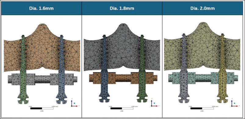
The effectiveness of skeletal orthopedic expansion largely depends on the primary stability of mini-implants. Bone-borne expanders utilize these implants for skeletal anchorage, facilitating the direct transmission of orthopedic forces to the basal bone and minimizing dental side effects. 11 It has been shown that bicortical mini-implant anchoring is better than monocortical mini-implant anchorage.10, 13 Studies have shown that the initial stability of mini-implants is closely related to their diameter. 11 Furthermore, securing bicortical anchorage has been associated with enhanced implant stability, which may contribute to more efficient skeletal expansion.10, 11, 14 Therefore, the present finite element model is intended to be hypothesis-generating, aiming to explore biomechanical trends in stress distribution and displacement associated with varying mini-implant diameters (1.6, 1.8, and 2.0 mm) under bicortical anchorage during bone-borne palatal expansion (Figure 1). The findings are not intended to predict clinical outcomes but to provide biomechanical insights that may inform future experimental and clinical investigations.
Finite Element Models Illustrating the Meshing and Configuration of Mini-implants with Three Different Diameters—1.6, 1.8, and 2.0 mm.
Materials and Methods
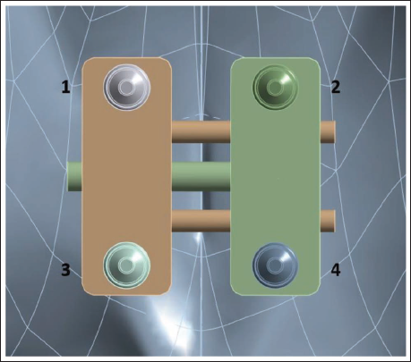
Cone-beam computed tomography (CBCT) data from a dry adult skull, with a slice thickness of 0.30 mm, were processed in specialized imaging software (Mimics v14.0, Materialize) to construct a finite element model. Following threshold-based segmentation, a three-dimensional virtual surface model of the skull was generated. Associated maxillofacial sutures were manually designed and incorporated into the model, each measuring approximately 1.5-2 mm in width. Three different bicortical mini-implant diameters were assessed in this study. The 3D skull models were imported into Autodesk Meshmixer (version 3.5; Autodesk) for volumetric mesh generation suitable for finite element analysis. Three-dimensional computer-aided design (CAD) models of the mini-implants (1.6, 1.8, and 2.0 mm in diameter; 11 mm in length) and the bone-borne maxillary skeletal expander (BioMaterials Korea, Seoul, Korea) were designed using Creo Parametric software (version 10.0.1.0; PTC), based on the actual manufacturer specifications. These designs were exported as stereolithography (STL) files for further processing. For accurate anatomical placement, the expander’s position was determined using CBCT images and clinical photographs, and aligned using posteroanterior cephalometric references within 3-Matic software. Across all three simulation conditions, only the implant diameter varied; the expander’s position remained unchanged (Figure 2).
The Expander with Four Mini-implants of the Same Diameter.
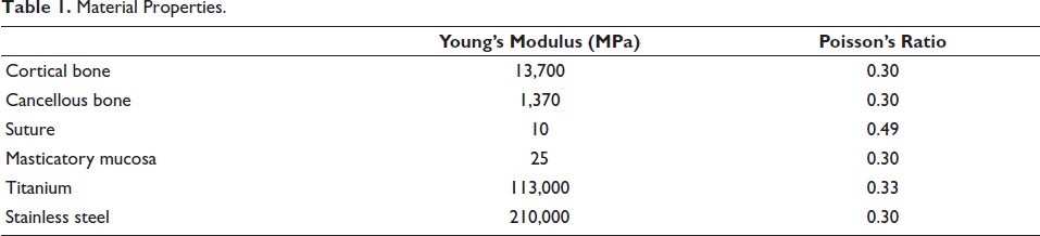
The finite element mesh was composed of tetrahedral elements. Each skull model consisted of approximately 207,817 elements and 350,697 nodes. Local remeshing was applied to the maxilla and associated sutures to enhance accuracy. The mini-implants were meshed as follows: the 1.6 mm implant had 15,218 elements and 23,959 nodes, the 1.8 mm implant had 16,215 elements and 25,250 nodes, and the 2.0 mm implant included 17,481 elements and 27,105 nodes. The expander mesh contained around 29,575 elements and 52,575 nodes. The skull, expander, and mini-implant models were all imported into ANSYS Workbench (version R22; ANSYS, Inc.) for finite element analysis. The material characteristics were assumed to be homogeneous, isotropic, and linearly elastic; therefore, isotropic assumptions may underestimate localized stress gradients, particularly in sutural regions. The Young’s modulus and Poisson’s ratio were determined for each component based on available literature (Table 1).3, 15, 16
Material Properties.
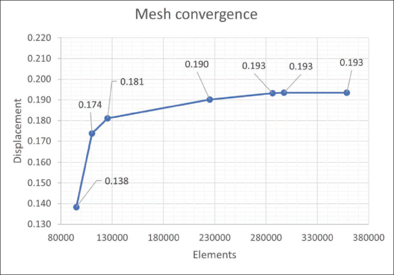
A mesh convergence test was performed to ensure the numerical accuracy and reliability of the finite element model. The progressive mesh refinement resulted in increasing displacement values that gradually approached a stable plateau, beyond which additional refinement produced negligible variation, confirming numerical convergence and mesh independence of the finite element model (Figure 3). For boundary conditions, the nodes associated with the foramen magnum were entirely immobilized, restricting all translational and rotational degrees of freedom. Meanwhile, the expander was not constrained in the transverse, sagittal, or coronal planes, allowing unrestricted expansion during the simulation. A single transverse displacement of 0.25 mm was applied to activate the expander, corresponding to one clinical MARPE screw turn. Clinically, maxillary skeletal expanders are typically activated by 0.2-0.25 mm per turn (corresponding to one-quarter turn of the expansion screw), once or twice daily during the initial phase of expansion. 10 Therefore, the applied displacement represents an early-stage, clinically relevant activation rather than the full expansion protocol, allowing the evaluation of initial stress distribution and skeletal response under controlled conditions. The stress distribution was analyzed using von Mises criteria, and directional displacement along the transverse, anteroposterior, and vertical planes was evaluated to assess the skeletal response. A coordinate system was constructed with the X-axis represented the transverse direction corresponding to lateral expansion of the maxillary halves, the Y-axis represented the anteroposterior direction, and the Z-axis represented the vertical direction.
Number of Elements and Displacement Used During the Mesh Convergence Test.
Result
Among the three diameters tested, the 1.6 mm bicortical mini-implant demonstrated the highest stress concentration around the peri-implant region, whereas the 1.8 and 2.0 mm implants exhibited comparatively lower stress levels, suggesting a biomechanical trend toward improved load distribution with increasing implant diameter. This suggests that smaller-diameter implants may lead to greater stress concentration at the peri-implant bone site, potentially increasing the risk of microdamage or reduced stability under functional loading. However, the overall differences in stress values among the three diameters were minimal, indicating that while implant diameter influences stress distribution, the magnitude of variation may not be clinically significant. The comparable performance of the 1.8 and 2.0 mm implants also suggests that beyond a certain threshold, increasing implant diameter may not substantially enhance biomechanical stability. These findings highlight the importance of considering implant diameter in relation to anatomical and clinical constraints when planning for skeletal anchorage in maxillary expansion procedures.
Stress Distribution at the Peri-implant Site
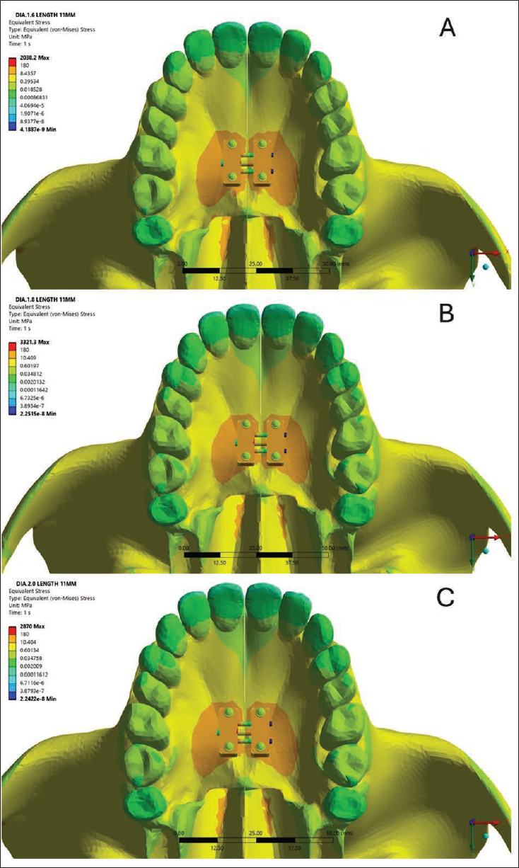
The analysis suggested that stress levels at the surrounding cortical contact zone decreased with increasing implant diameter (Figure 4). The 1.6 mm bicortical mini-implant recorded the highest stress value of 3.20 MPa, suggesting that smaller-diameter implants may transmit greater mechanical loads to the surrounding cortical bone. In comparison, the 1.8 and 2.0 mm implants showed reduced stress levels of 2.28 and 2.22 MPa, respectively, indicating improved stress distribution with increased implant diameter. Although the numerical differences appear modest, the trend supports the biomechanical advantage of using slightly larger implants in minimizing localized stress.
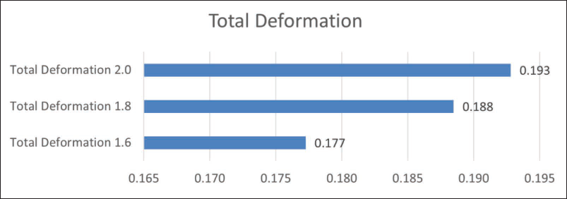
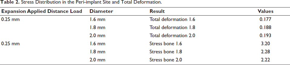
The displacement measured in the palatal bone showed a slight increase with larger implant diameters. The 2.0 mm model demonstrated comparatively higher palatal displacement, with a maximum value of 0.1993 mm, while the 1.6 mm model exhibited the lowest at 0.177 mm (Figure 5). These findings indicate that although larger implants reduce stress at the bone–implant interface, they may be associated with slightly greater deformation of the palatal bone under loading conditions (Table 2).
(A, B, C) The Equivalent (von Mises) Stress Distribution Across the Maxilla and Palatal Expander Assembly Using 1.6, 1.8 and 2.0 mm Diameter Mini-implant.
Total Deformation (Millimeter) for All Three Anchorage Models.
Stress Distribution in the Peri-implant Site and Total Deformation.
Stress in the Mini-implants
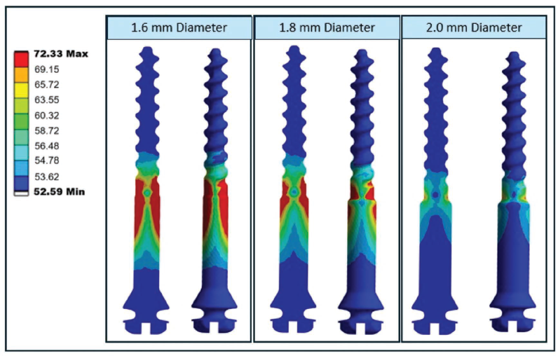
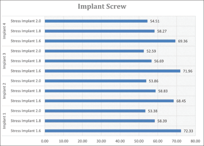
von Mises stress of the 1.6, 1.8, and 2 mm mini-implants was also evaluated (Figure 6), and the 1.6 mm implant exhibited the highest internal stress, indicating a greater concentration of mechanical load within the implant structure itself (Figure 7). In comparison, the 1.8 and 2.0 mm implants demonstrated lower internal stress values. This finding suggests that smaller-diameter implants are more susceptible to mechanical strain under functional loading, potentially increasing the risk of structural fatigue or failure. Lower internal stress observed in the larger-diameter implants reflects a more favorable load distribution, supporting their biomechanical advantage in clinical applications where long-term stability and durability are essential.
Stress Distribution Within Mini-implants of Three Different Diameters—1.6, 1.8, and 2.0 mm.
von Mises Stress Values (in MPa) Within Mini-implant Screws of Varying Diameters (1.6, 1.8, and 2.0 mm) Across Four Different Implant Positions.
Stress in the Expander
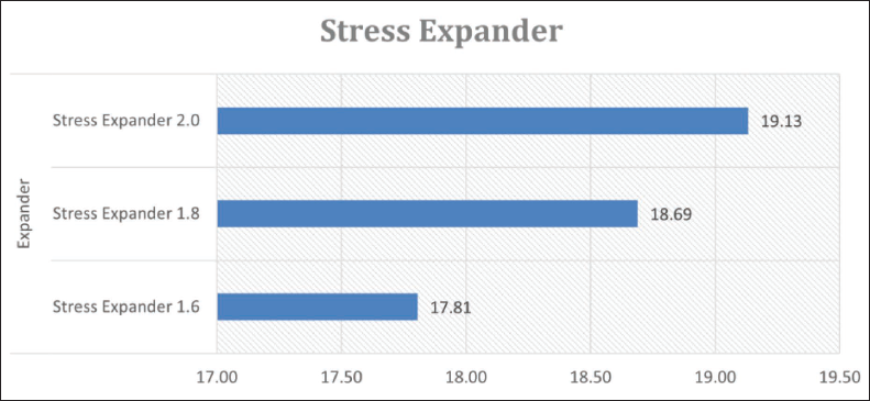
Stress analysis of the expander component demonstrated that the use of smaller-diameter mini-implants resulted in lower stress transmission to the expander. The internal stress values observed in the expander varied with implant diameter, measuring 17.81 MPa for the 1.6 mm implant, 18.69 MPa for the 1.8 mm implant, and reaching 19.13 MPa for the 2.0 mm implant (Figure 8), indicating a gradual increase in stress with larger implant sizes. Although the differences were relatively minor, the trend indicates that larger-diameter implants may lead to slightly greater mechanical loading on the expander. From a biomechanical standpoint, lower stress within the expander is desirable as it may contribute to improved durability of the device and a reduced risk of material fatigue over time.
von Mises Stress Values (in MPa) Within the Expander for Mini-implants of 1.6, 1.8, and 2.0 mm Diameters.
Deformation Along X, Y, Z Axis
The directional deformation (in mm) was evaluated in three axes (X: transverse, Y: anteroposterior, Z: vertical) for right sides and (–X: transverse, –Y: anteroposterior, –Z: vertical) for left sides across three mini-implant diameters (Figure 9).
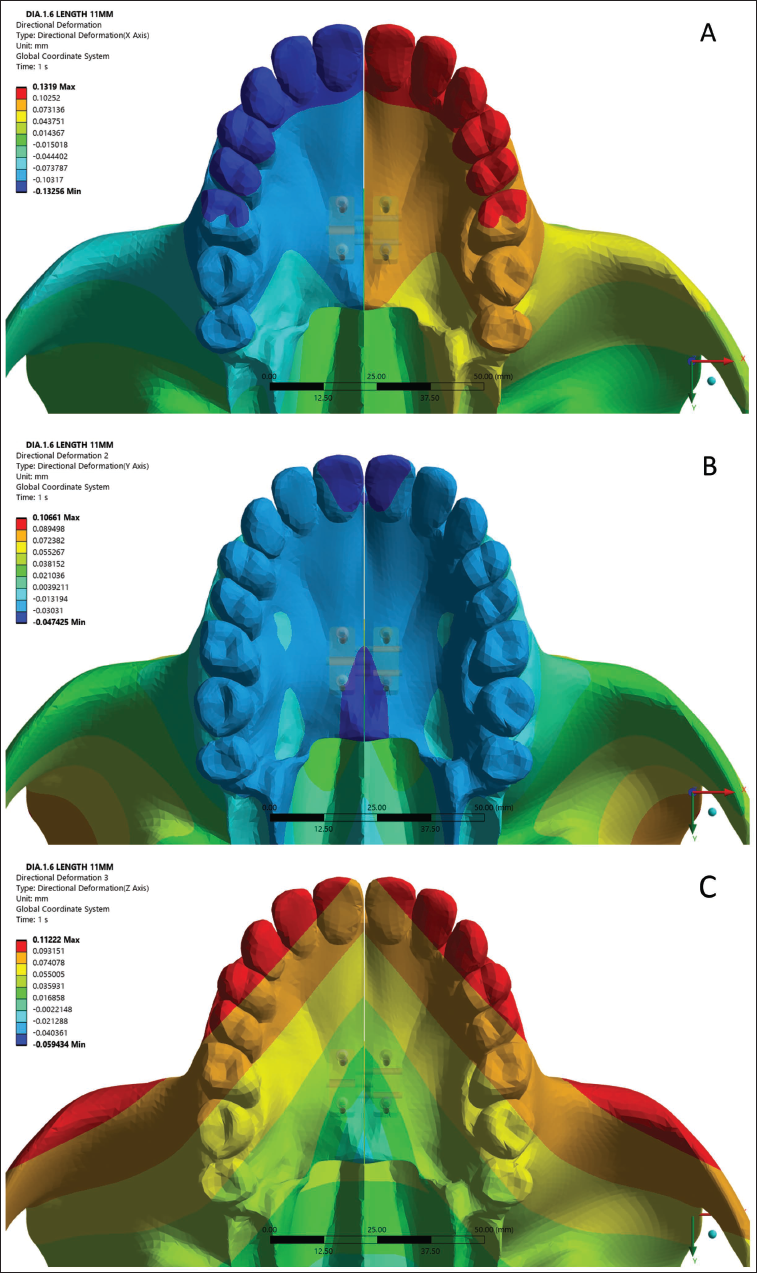
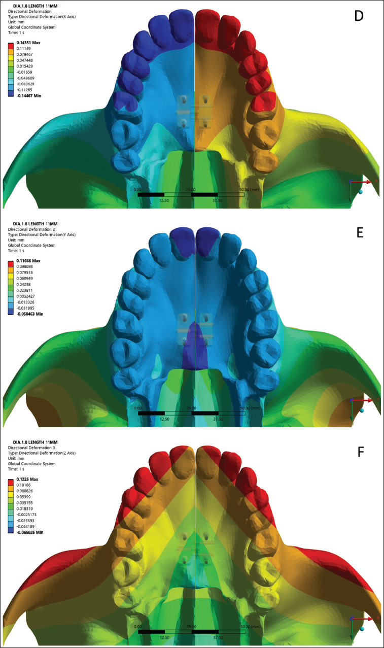
(A) Directional Deformation of 1.6 mm Diameter Mini-implant Along X-axis. (B) Directional Deformation of 1.6 mm Diameter Mini-implant Along Y-axis. (C) Directional Deformation of 1.6 mm Diameter Mini-implant Along Z-axis. (D) Directional Deformation of 1.8 mm Diameter Mini-implant Along X-axis. (E) Directional Deformation of 1.8 mm Diameter Mini-implant Along Y-axis. (F) Directional Deformation of 1.8 mm Diameter Mini-implant Along Z-axis. (G) Directional Deformation of 2 mm Diameter Mini-implant Along X-axis. (H) Directional Deformation of 2 mm Diameter Mini-implant Along Y-axis. (I) Directional Deformation of 2 mm Diameter Mini-implant Along Z-axis.
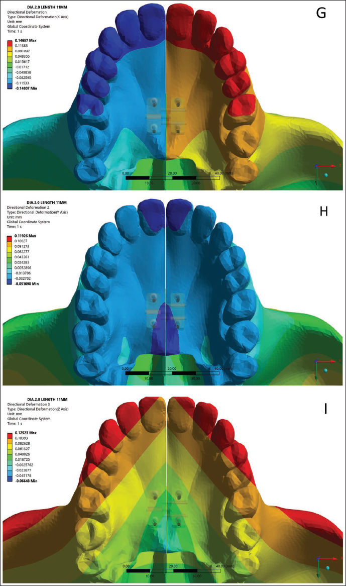
In the X-direction (Transverse)
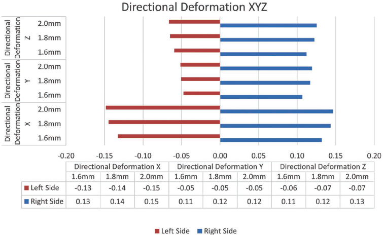
The deformation values progressively increased in magnitude with implant diameter on both sides. On the left side, deformation increased from −0.13 mm (1.6 mm implant) to −0.15 mm (2.0 mm implant), while the right side showed corresponding positive values from 0.13 to 0.15 mm (Figure 10). This symmetric transverse expansion suggests a uniform lateral displacement pattern, demonstrating a biomechanical trend toward greater deformation with increasing implant diameter.
Bar Graph Illustrating Directional Deformation in the Transverse (X), Anteroposterior (Y), and Vertical (Z) Planes for Both the Left (Red) and Right (Blue) Sides of the Maxilla, Using Mini-implants of 1.6, 1.8, and 2.0 mm Diameters.
In the Y-direction (Anteroposterior)
The deformation measurements were minimal and showed little variation across the different implant diameters. On the left side, values remained between −0.05 and −0.06 mm, while the right side showed a range of 0.11 to 0.12 mm (Figure 10).
In the Z-direction (Vertical)
Vertical displacement varied from −0.06 to −0.07 mm on the left and from 0.11 to 0.13 mm on the right (Figure 10). The values remained nearly constant across all implant diameters.
Discussion
In adult patients, where the midpalatal suture exhibits increased interdigitation and resistance to separation, ensuring strong primary stability of the mini-implants is critical to tolerate the higher forces applied during expansion. 11 As bone-borne devices transmit orthopedic forces directly to the basal bone through skeletal anchorage, the structural integrity and stability of the mini-implants are key factors influencing the success of the expansion procedure. Furthermore, research indicates that bicortical anchorage provides greater stability than monocortical anchorage in orthodontic applications, making it a more favorable approach for resisting displacement during treatment. 10
According to findings by Lee et al., 10 employing bicortical anchorage for mini-implants has been shown to improve their mechanical stability, lower the likelihood of deformation or fracture, facilitate more uniform expansion, and enhance skeletal widening during bone-borne palatal expansion. Despite these benefits, the depth of bicortical mini-implant anchorage does not significantly influence implant stability, deformation, or transverse bone displacement. 17 Building on this, the current study focuses on examining whether variations in mini-implant diameter, rather than its depth, can positively affect anchorage stability and improve the outcomes of maxillary skeletal expansion.
This study examined the effects of three distinct bicortical anchoring sizes that permit expansion in an adult patient using a skull model. Three distinct clinical simulations were developed, each incorporating a different mini-implant diameter (1.6, 1.8, and 2.0 mm), with the location of the bone-borne expander remaining unchanged in all simulations. Only the mini-implant diameter varied throughout the three clinical scenarios. In order to investigate the variations among the three distinct diameters of bicortical anchorage and to ascertain whether the diameter of bicortical anchorage is relevant, all three of these clinical scenarios have been simulated using the FEM.
An in vitro investigation conducted by Copello et al., 11 demonstrated that mini-implants utilizing bicortical anchorage exhibited enhanced mechanical stability when compared to those relying solely on monocortical engagement. However, due to the technical challenges and anatomical limitations often associated with achieving bicortical placement, it may not always be practical in clinical settings. The study further revealed that mini-implants with larger diameters specifically 1.8 and 2.0 mm using monocortical anchorage outperformed smaller diameter implants (1.6 mm) with bicortical support in terms of mechanical strength. These findings suggest that increasing the diameter of mini-implants can improve anchorage reliability. Therefore, when bicortical engagement is not feasible, particularly in the anterior palate, selecting mini-implants with larger diameters is advisable to ensure optimal mechanical performance, especially when used in conjunction with tooth-bone-borne expanders.
Limitations
The finite element model was based on an idealized representation of craniofacial anatomy and, therefore, does not reflect individual anatomical variations encountered in clinical practice. All tissues were modeled as homogeneous, isotropic, and linearly elastic, which may result in an underestimation of localized stress concentrations, particularly within sutural regions. In addition, the model was not supported by direct experimental or clinical validation. Consequently, as with all finite element investigations, the results should be interpreted as indicative of biomechanical behavior and trends rather than exact predictors of clinical outcomes.
Conclusion
Influence of diameter and bicortical anchorage on stability
Mini-implant stability is significantly affected by both implant diameter and bicortical anchorage. The 2.0 mm mini-implants exhibited comparatively lower stress and deformation values, suggesting a biomechanical trend toward enhanced mechanical behavior.
Directional deformation and transverse expansion
In terms of deformation along the X, Y, and Z axes, the 2 mm bicortical mini-implant exhibited slightly higher displacement in the transverse plane, suggesting a biomechanical trend toward greater expansion response.
Clinical implications for mini-implant selection
The outcomes of this study suggest the use of larger diameter mini-implants in clinical practice, as they offer enhanced stability and more effective orthopedic expansion. These findings are particularly relevant when full bicortical engagement is technically difficult or anatomically limited.
Footnotes
Authors Contribution
Chandana TK: Conceived the research idea, designed the study, performed the finite element analysis, and drafted the manuscript.
Manas G: Contributed to study design, data analysis, and manuscript writing.
Jithesh Kumar K: Supervised the study and provided overall guidance and final approval of the manuscript.
Panjami Mearish: Contributed to literature review and manuscript drafting.
Steve Mathew Jacob: Provided critical revisions and contributed to manuscript editing.
Ashwathi N: Assisted in data analysis and manuscript preparation.
Declaration of Conflict of Interests
The authors declared no potential conflicts of interest with respect to the research, authorship, and/or publication of this article.
Ethical Approval and Informed Consent
As the present study is a finite element analysis conducted using computer-simulated models, ethical committee approval and informed consent were not required.
Funding
The authors received no financial support for the research, authorship, and/or publication of this article.