
Abstract
Objective
The study was conducted to analyze the stress distribution and displacement due to three different vertical positions of the mini-implant assisted rapid palatal expansion (MARPE) appliance.
Methods
A three-dimensional finite element meshed model was created of the maxillofacial complex with the help of cone beam computed tomography (CBCT) digital imaging and communication in medicine (DICOM) data of a patient with transverse maxillary deficiency using materialise interactive medical image control system (MIMICS) software. Three different groups with varying expander heights were used to study the expansion effects on the maxillofacial structures. von Mises stress and displacement at various skeletal and dental points were evaluated using ANSYS software.
Results
In the midpalatal suture, the posterolateral portion of the hard palate and the maxillary and pterygoid bones showed the greatest amount of stress distribution and displacement pattern. Group 1 showed the maximum amount of transverse displacement compared to groups 2 and 3. Sagittally, all the teeth had a forward displacement. Vertically, groups 2 and 3 showed clockwise rotation of the occlusal plane, while all teeth showed downward displacement in group 1.
Conclusion
In conclusion, a V-shaped expansion in the maxilla with a superior and posterior vertex was noted. Group 1, that is, appliance placed in close approximation to the palate, showed greater displacement compared to groups 2 and 3.
Keywords
Introduction
Maxillary transverse deficiency (MTD) affects nearly 8% of deciduous dentition, 21% of mixed dentition, and less than 10% of adults. 1 The most common clinical presentation is the presence of unilateral/bilateral crossbite. Patients presenting with V-shaped palate, severe crowding, increased buccal corridors, and obstructive sleep apnea also require transverse expansion to improve esthetics and function. 2 Correcting MTD requires separation of the midpalatal suture (MPS), a procedure that has traditionally been achieved using rapid maxillary expansion (RME) in growing children.
As an individual grows older, the difficulty in separating the MPS increases, primarily due to the interlocking of sutures and the resistance posed by the zygomatic and pterygoid buttresses. 3 The effectiveness of traditional RME in older age groups raises uncertainties, with documented instances of more pronounced detrimental dentoalveolar and periodontal effects. These include tipping, bending of alveolar bone, extrusion of posterior teeth, loss of alveolar bone, fenestration, and dehiscence.4–6
Severe atresia and maxillary constriction cases require surgical intervention for correction of MTD, such as surgically assisted rapid palatal expansion (SARPE). SARPE is an invasive and expensive procedure; therefore, clinicians prefer less invasive procedures. Oliviera et al. compared transverse expansion with mini-implant assisted rapid palatal expansion (MARPE) and SARPE and concluded that MARPE resulted in a greater skeletal and parallel expansion of the maxilla, while a V-shaped opening was noted with SARPE. 7
In 2010, Lee et al. 8 introduced the technique of MARPE, which has proven to be superior to traditional RME in correcting MTD in adolescents and adults. MARPE is a modification of conventional RME that incorporates mini-implants for skeletal anchorage, resulting in more effective skeletal expansion with fewer dentoalveolar and periodontal side effects. It can be used as an adjunctive procedure in correcting sagittal relationships, as in protraction facemask and alternative rapid maxillary expansion and constriction (Alt-RAMEC) procedures. 9 Several modifications of the appliance have been introduced to maximize the skeletal effects. Various clinical studies have validated the effectiveness and long-term stability of this appliance.10, 11
The positioning of the appliance is largely dictated by the experience of the practitioner and the anatomic constraints. 12 Severe constriction with increased palatal depth and in atresia cases may pose challenges, such as the unavailability of the appropriate size of the screw and lateral mucosal damage. Matsuyama et al. 13 have pointed out that RME often does not act effectively in a high-arched palate. Therefore, alteration in the design can be done so that the expander is placed at varying heights to aid in expansion and prevent lateral mucosal damage.
With the finite element model, de Sousa Araugio et al. 12 evaluated the degree of dental inclination during RME with different heights of the expander screw. Fernandes et al. 14 evaluated stress distribution and displacement patterns with varying heights of expander screw of RME appliance. André et al. 15 evaluated force distribution patterns with an individualized height adjustment of the MARPE appliance using finite element analysis (FEA). The finite element method (FEM) is an engineering tool commonly used to calculate stress and deformations in complex structures, making it valuable in biomedical research. FEM offers a non-invasive and accurate method to obtain quantitative and detailed data regarding physiological responses in tissues, including the periodontal ligament (PDL) and the alveolar bone. 16 By using FEM, it becomes possible to anticipate tissue responses to orthodontic mechanics. Therefore, we aimed to study the stress distribution and displacement due to three different vertically positioned designs of the MARPE appliance as it is imperative to validate the benefits and effectiveness of the appliance upon alteration in the design parameters.
Material and Methodology
The study was approved by the Institutional Ethical Committee. A cone beam computed tomography (CBCT) scan (i-CAT Vision; Hatfield, PA, 120 kVp, 5 mA, 130.0 FOV, exposure time of 4 seconds, resolution 0.40) of the maxillofacial complex of a 16-year-old male patient with transverse maxillary deficiency was taken. The patient had an orthognathic maxilla [sella–nasion point A angle (SNA) = 82°] and orthognathic mandible [sella–nasion point B angle (SNB) = 79°] with an average growth pattern [Frankfort-mandibular plane angle (FMA) = 25°], overjet of 2 mm, and overbite of 30%, with a decreased jugal–jugal points (J–J) value of 54 mm as measured on posteroanterior (PA) cephalogram. There was increased buccal corridor, unilateral posterior crossbite with anterior crowding, and the patient was planned for treatment with MARPE appliance.
The raw volumetric data were obtained from a CBCT scan, which was saved as a digital imaging and communication in medicine (DICOM) file. The data were processed using the materialise interactive medical image control system (MIMICS) software (version 8.11, Materialise: Leuven, Belgium), which allowed for the segmentation of the three-dimensional (3D) model into maxillary cortical, cancellous bones, and teeth. To improve accuracy and address any voids in the model, the data were transferred to Solidworks software, where refinements were made to the 3D model of the maxillofacial bones, along with the removal of any imperfections.
However, due to the thinness of the PDL in the initial data, reverse engineering reconstruction was necessary to create a solid PDL model. The Geomagic software facilitated this process, and a Boolean operation was subsequently applied to integrate the PDL model with the rest of the craniofacial 3D model. Once all the necessary steps were completed and the data were cleaned up, a final 3D model of the patient’s skull in STL file format was obtained.
This comprehensive model consisted of seven bones, namely, the frontal, nasal, maxillary, zygomatic, pterygoid, palatal, and temporalis bones, as well as ten sutures, including the frontonasal, frontomaxillary, zygomaticomaxillary suture (ZMS), zygomaticotemporal, zygomaticofrontal, pterygomaxillary suture (PTM), internasal, nasomaxillary, sphenomaxillary, and MPS, each with a thickness of 0.8 mm. Additionally, the 16 teeth were included in the model, along with a layer representing the PDL, which had a thickness of 0.2 mm.
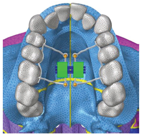
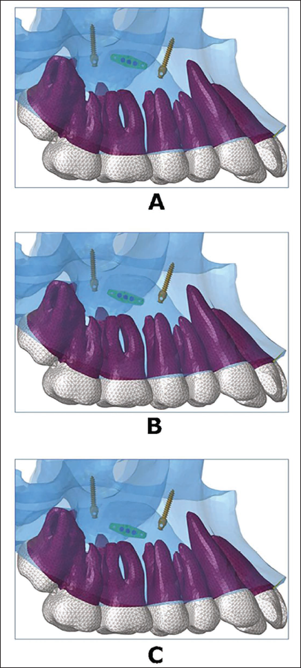
Using 3D computer-aided design (CAD) data, three different rigid models were created, with four holes: Two anterior holes located between the first and second premolars, and two rear holes were positioned near the first molar, for orthodontic mini-implant placement. The expander was connected to the first premolars and first molars and was secured using four 1.5 × 11 mm orthodontic mini-implants to the palatal and nasal cortices, that is, bicortical. It was positioned between the second premolar and first molar in all three models. In group 1, the appliance was placed in close approximation to the palate, while it was placed 20 mm and 15 mm from the occlusal table in groups 2 and 3, respectively (Figures 1 and 2). These models were in accordance with a study conducted by de Sousa Araugio et al., 12 wherein different vertical positioning of the RME appliance was evaluated.
Design of Mini-implant Assisted Rapid Palatal Expansion (MARPE) Model.
Vertical Positioning of the Expander: Close to the Palate, 20 mm from the Occlusal Plane, and 15 mm Occlusal Plane, Respectively.
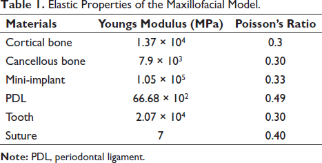
The models were assumed to be homogeneous and linearly elastic, and material properties were assigned as shown in Table 1. 17 The 3D models were then imported into the HyperMesh software (Altair Computing, Inc., Troy, MI), and meshing of the 3D model was carried out. The tetrahedral element was chosen for all structures because the convergence test resulted in 99.9% accuracy. The final meshed models consisted of 579,088 tetrahedral elements and 107,858 nodes.
Elastic Properties of the Maxillofacial Model.
Nodes along the foramen magnum and cranial nodes of the cranium lying on the symmetrical plane were constrained in all degrees of freedom, with zero displacements and zero rotation. 18 The loading condition corresponded to the application of one-fourth turn, simulating the expansion of 0.25 mm. Load and boundary conditions remained the same for all four groups. The database file was then transferred to ANSYS v. 12.1 software (ANSYS Inc., Canonsburg, PA) for post-processing.
Results
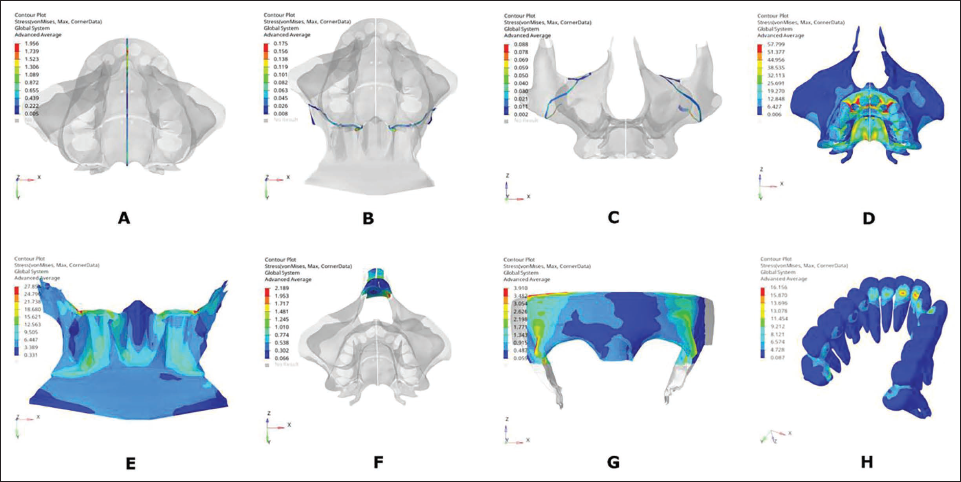
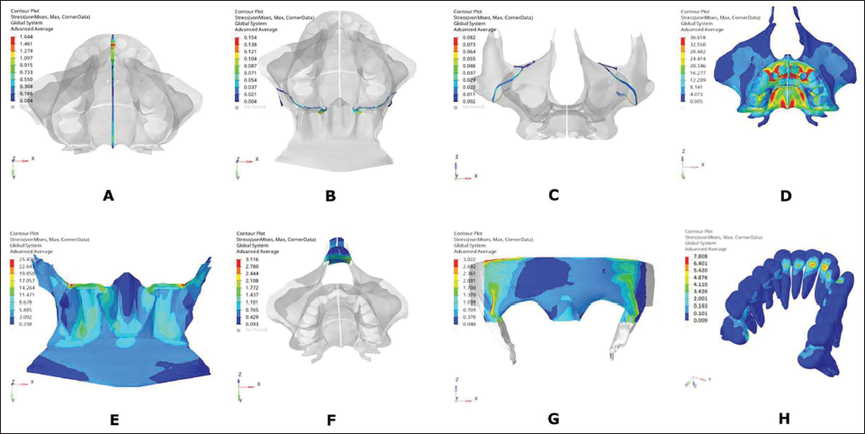
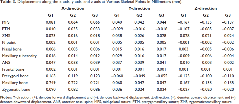
Linear elastic analysis was performed. Stress distribution (von Mises) and displacement were noted over the sutures (MPS, zygomaticomaxillary, and pterygoid), skeletal points (N point, frontal bone, maxillary bone, zygomatic bone, nasal bone, anterior nasal spine (ANS), maxillary tuberosity, and pterygoid bone), and dental points (U1, U2, U3, U4, U5, U6, and U7) as given in Tables 2 and 3. Contour graphs depicting areas of high-stress concentration for each of the designs were generated, wherein the red and blue areas represented regions of high and least stresses, respectively (Figures 3–5).
von Mises Stress (MPa) Distribution over Maxillofacial Structures in Group 1.
von Mises Stress (MPa) Distribution over Maxillofacial Structures in Group 2.
von Mises Stress (MPa) Distribution over Maxillofacial Structures in Group 3.
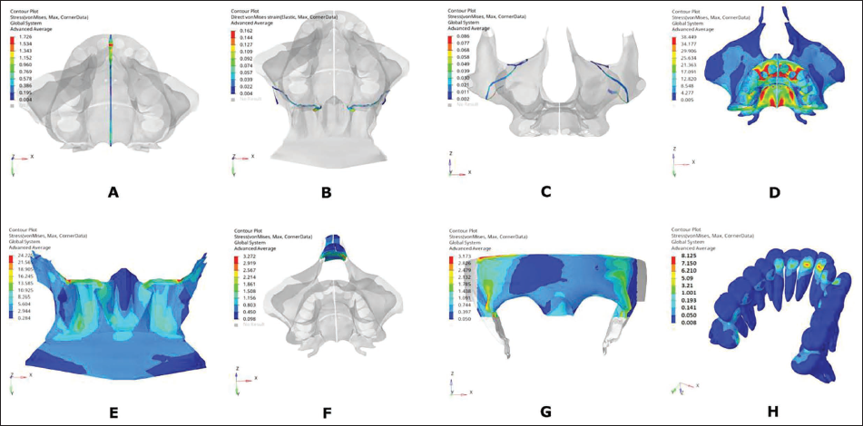
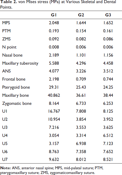
Maximum stress of 2.048 MPa, 1.644 MPa, and 1.652 MPa was noted along MPS suture in groups 1, 2, and 3, respectively. A lesser magnitude of stresses was observed with PTM and ZMS compared to MPS in all three groups (Table 2, Figure 6B). Maximum stress of 40.862 MPa, 36.61 MPa, and 38.44 MPa was noted in the maxillary bone, and 29.31 MPa, 25.43 MPa, and 24.25 MPa in pterygoid bone in groups 1, 2, and 3, respectively. In the maxilla, the maxillary tuberosity had higher stresses than the ANS in all three groups. Least stresses were noted with the N point and nasal bone. Overall, stresses with group 1 were higher than those in groups 2 and 3 at the various skeletal points.
von Mises stress (MPa) at Various Skeletal and Dental Points.
von Mises Stresses (MPa) at Dental and Skeletal Points.
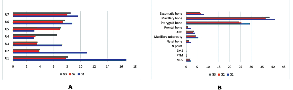
In group 1, the incisors showed higher stresses of 16.767 MPa than the molar teeth (9.632 MPa), with the least stresses over the premolars. Stresses in the anterior and posterior regions were comparable in groups 2 and 3, as shown in Figure 6A.
Along the transverse direction, the ZMS had the least amount of displacement, while the highest displacement of 0.081 mm was noted in MPS in group 1 (Table 3). This displacement was larger in group 1, followed by groups 2 and 3 (Figure 7B). In the sagittal direction, the PTM had a posterior displacement (Figure 7D). Vertically, the three sutures had a downward displacement in all three groups, with group 1 having the highest greatest displacement value (Figure 7F).
Displacement along the x-axis, y-axis, and z-axis at Various Skeletal Points in Millimeters (mm).
Transverse, Sagittal, and Vertical Displacements (mm) of Dental and Skeletal Point in Groups 1, 2 and 3.
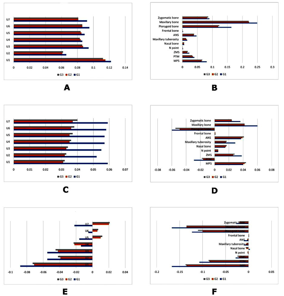
Among the three groups under comparison, the maxillary and the pterygoid bones exhibited the greatest transverse displacement. Minor displacement was noted along the N point, nasal, and frontal bones.
Displacements of 0.249 mm, 0.222 mm, and 0.221 mm were noted in the maxilla in groups 1, 2, and 3, respectively (Figure 7B). Sagittally, the pterygoid bone had a posterior displacement in group 1 > group 2 > group 3 (Figure 7D). Vertically, the pterygoid, zygomatic, and maxillary bone had a downward displacement in all three comparison groups. Group 1 had the highest displacement along the vertical direction for most of the skeletal points.
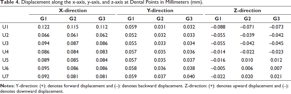
A transverse displacement of 0.122 mm at the central incisors was highest in group 1, followed by 0.115 mm in group 2 and 0.112 mm in group 3 (Table 4). A similar amount of transverse displacement was noted from the canine to the second molars in all three groups, with group 1 being the highest (Figure 7A). All the teeth had a forward displacement in all three groups, with group 1 showing the highest displacement magnitudes (Figure 7C). Downward displacement of all teeth was noted in group 1, while groups 2 and 3 depicted downward movement in anterior and upward movement in posterior teeth (Figure 7E).
Displacement along the x-axis, y-axis, and z-axis at Dental Points in Millimeters (mm).
Discussion
Treatment of MTD can be achieved using various treatment modalities such as slow expansion, rapid expansion, or surgical, depending upon sutural ossification. In recent years, MARPE appliance has been widely used for skeletal correction of MTD. Although the viability of the MARPE appliance has been studied extensively over the past few years, ways to improve the design of the appliance to enhance its clinical efficiency continue to be explored. Placing the expander close to the palate is advantageous as it is close to the center of resistance of the maxilla, while de Sousa Araugio et al. 12 suggested placing it above the center of resistance of the first molar for RME. Placing the appliance away from the palate can cause tongue interferences and can lead to possible loosening of the appliance.
In the past, FEM studies12–15 have been conducted to assess force distribution and deformation of the maxillary bone, teeth, and surrounding structures with varied vertical expander positioning of RME appliance, but the literature is deficient in terms of MARPE appliance. Thus, this study aims to fill this gap by investigating the impact of three different vertically positioned designs of MARPE appliances on maxillofacial structures. The findings could have implications for optimizing MARPE techniques and minimizing unwanted dentoalveolar and periodontal effects.
Stress
Among the three groups, group 1, where the expander was placed close to the palatal vault, depicted the highest stress distribution, followed by groups 2 and 3. Stress distribution among the sutures showed that the MPS had the highest values, trailed by the PTM and the ZMS, indicating the influence of the expander screws proximity to the MPS. Examining stress distribution across the bones, the maxillary bone exhibited the highest stress, followed by the pterygoid, zygomatic, nasal, and frontal bones. Specifically, elevated stress was noted in the posterolateral section of the hard palate, near the implants, and the anterior dentoalveolar region within the maxillary bone. This pattern is likely influenced by the resistance provided by the pterygomaxillary, zygomaticomaxillary, and nasomaxillary buttresses. 19 Notably, the increased stress values observed in the MPS, maxilla, and the pterygoid bones can be attributed to the bicortical engagement of the mini-implants.
Maxillary expansion through the MARPE appliance not only affects the maxillary bone but also has implications for other maxillofacial structures, including the zygomatic, frontal, and nasal bones. These findings are consistent with previous clinical and FEM studies.20–22 The maxillary incisors experienced higher stress than molars and premolars/canines due to initial appliance activation, primarily affecting anterior teeth with smaller root surface areas and thinner PDL. Although initial forces are greater in posterior teeth during MARPE treatment, both anterior and posterior teeth contribute to the overall expansion process.
Displacement
The three groups exhibited varying sutural separation. In terms of transverse movement, the MPS exhibited the most substantial displacement, succeeded by the PTM and ZMS. The maxillary bone displayed the greatest displacement, followed by the pterygoid, zygomatic, nasal, and frontal bones. Regarding sagittal movement, the pterygoid and the PTM suture moved posteriorly, while the maxillary and the zygomatic bones shifted anteriorly. In the vertical dimension, there was a downward movement observed in all three sutures (MPS, PTM, and ZMS), as well as the maxilla, pterygoid, and zygomatic bones. Nasal and frontal bones displacement was negligible in all directions. Similar to our study, Jafari et al. 23 and Song et al. 21 also found expansion of the inferior pterygoid process due to transverse orthopedic forces, resulting in posterior, lateral, and downward displacement of the pterygoid bone and PTM suture. Additionally, we observed a forward and downward displacement of the maxillofacial complex, which aligns with previous studies.21, 22
The anterior teeth had higher displacement along the transverse direction, whereas lesser displacement was noted with the posterior teeth. This corroborates with the findings of Naveda et al., 24 where they found greater displacement at the ANS. The pivot point for maxillary rotation is primarily situated at the frontomaxillary suture, resulting in the creation of a triangular intermaxillary diastasis. This diastasis exhibits a base aligned with the upper incisors and an apex extending to the nasal cavity. The intricate network of surrounding bones and the resistance posed by the pterygomaxillary buttress may account for this phenomenon. This observation is substantiated by Ghoneima et al.’s 25 clinical study, which examined the impact of RME on anterior craniofacial structures.
A FEM study by Gautam et al. 18 yielded complementary results, revealing that conventional RME induces maximum stresses along the frontomaxillary, nasomaxillary, and frontonasal sutures. Furthermore, they determined that the horizontal center of maxillary rotation resides between the lateral and medial pterygoid plates. Wertz 26 studied the displacement pattern of maxillary separation with age. In younger individuals, the fulcrum tends to be situated closer to the frontomaxillary suture, whereas, in adolescents, it shifts downward, nearer to the point of the force application. This disparity is likely attributable to the resistance offered by the circummaxillary sutures during maxillary separation. In contrast to this, Cantarella et al. 27 concluded that the zygomaticomaxillary complex undergoes rotation around a center of rotation located within the proximal portion of the zygomatic process of the temporal bone.
Sagittally, there was a forward displacement observed in all the teeth, suggesting the presence of an anterior force component exerted on the extremities of the expander and the supporting teeth. This was also noted by de Sousa Araugio et al. 12 with RME. When the MARPE appliance is activated, it creates a force that widens the MPS. The maxilla expands transversely and causes the maxilla to move in the forward direction. As the maxilla moves forward, it causes the dentition to move forward as well, leading to a forward thrust.
Regarding the vertical direction, downward displacement of anterior teeth and upward displacement of posterior teeth were seen in groups 2 and 3, while in group 1, all teeth had downward displacement. A downward tendency of deformation was observed in the central portion of the hyrax screw. Therefore, a reactive and upward deformation tendency was registered in the expander extremities, thus generating extrusion tendencies for both premolars and molars. This was in accordance with the FEM study by André et al., 15 who reported a minor side effect of tipping of teeth with increased vertical positioning of the expander. While Bassarelli et al. 28 did not observe an increase in the height of the crowns of the maxillary teeth during RME. Reed et al., 29 however, reported extrusion of the molars with banded and bonded expanders.
The study’s findings indicated that all three designs yielded positive results in expanding sutures. This suggests that we can employ the expander at different vertical positions while still achieving effective sutural expansion. The optimal location for the expander placement would be near the palate since it positions the appliance close to the center of resistance of the maxilla, facilitating skeletal expansion rather than primarily dental expansion. However, in cases where the palatal vault is narrow and necessitates placing the expander farther from the palate, it is advisable to consider a bicortical engagement design as a clinical recommendation. This design may enhance the effectiveness of the MARPE appliance under such clinical situations.
This study examined the initial impact of the expander, focusing on the stress distribution and displacement following a single turn of the expander. However, it is important to recognize that stress distribution and displacement could exhibit different patterns as the expansion progresses and the suture gradually opens. The study encountered methodological challenges as it assumed linear behavior in its model under load, while biological tissues often demonstrate non-linear responses to mechanical forces. Since some degree of approximation is a limitation of FEM studies, our findings must be confirmed in vivo before they are clinically applied.
Conclusion
The following conclusions were drawn from the study:
All three designs demonstrated the ability to cause sutural expansion.
Alterations in the vertical positioning of the appliance impacted the stress distribution across the maxillofacial complex.
A V-shaped expansion occurred in the maxilla, featuring a superior and posterior vertex.
Group 1, where the appliance was positioned in close proximity to the palate, exhibited greater transverse displacement in comparison to groups 2 and 3.
A clockwise rotation of the dentition was noted with groups 2 and 3.
Footnotes
Acknowledgments
Not applicable.
Authors’ Contributions
PR gave the concept and design for the appliance. VG treated all the subjects and analyzed and interpreted all the data. TT and AK contributed to writing the manuscript. All authors read and approved the final manuscript.
Availability of Data and Materials
The datasets used and/or analyzed during the current study are available from the corresponding author on reasonable request.
Declaration of Conflicting Interests
The authors declared no potential conflicts of interest with respect to the research, authorship, and/or publication of this article.
Ethical Approval and Consent to Participate
The study protocol was approved by the Institutional Ethical Committee of Maulana Azad Institute of Dental Sciences No. F./18/81/MAIDS/Ethical Committee/2016/3259. Informed consent for CBCT was obtained from parent of the subject at the start of the study.
Funding
The authors received no financial support for the research, authorship, and/or publication of this article.
Informed Consent
Informed consent for publication was obtained from parent of the subject at the start of the study.