
Abstract
Orthodontists, on a day-to-day basis, have started to use bone screws for various tooth movements such as distalization, retraction, intrusion, etc. The most common sites for the placement of bone screws are IZC6 and IZC7 with an angulation of 55° to 70°. Their added advantage is an extra-radicular site with rare chances of failure. Failure of these IZC screws may take place due to improper placement or improper angulation, which may lead to inaccurate ideal final angulation, leading to trauma to the buccal mucosa, and inter radicular placement of the IZC screw. Asymmetrically placed IZC screws on the left and right side of the mouth can lead to alteration of biomechanics. A clinician usually finds it challenging to find a purchase point of the cancellous bone and to place it at the correct angulation, which needs to be achieved for the success of the bone screw. Herein, fabrication of a guide for the accurate placement of the IZC screws, using the basic armamentarium available in a clinic, is demonstrated. The method is economical, quick, non-tedious, and accurate.
Absolute anchorage systems have stormed the world of orthodontics over the past two decades with their ability to produce skeletal anchorage, converting borderline surgical cases into non-surgical and extraction cases into non-extraction or even bringing about the aesthetic impact which was difficult to achieve by conventional mechanics. 1
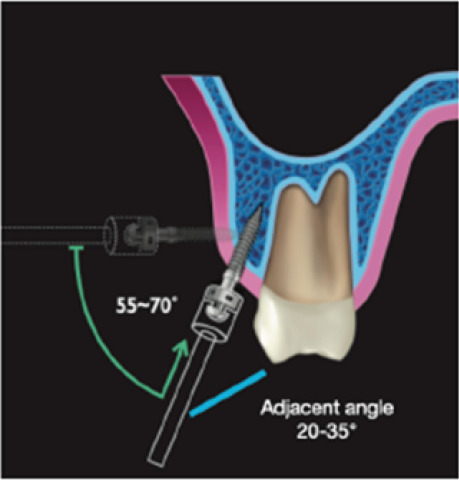
Orthodontists, on a day-to-day basis, have started to use bone screws for various tooth movements such as distalization, retraction, intrusion, etc. The most common sites for the placement of bone screws are IZC6 and IZC7 with an angulation of 55° to 70°. The preferred site for placement lies higher and lateral to the first and second molar region. While some authors (Lin) prefer bone screws to be placed in the first and second molar region, others (Liou) opine a more anterior placement, closer to the MB root of the first molar. 1
The added advantage of bone screws is an extra-radicular site with rare chances of failure. Failure of these IZC screws may take place due to improper placement or improper angulation which may lead to
inaccurate ideal final angulation, leading to trauma to the buccal mucosa;
inter radicular placement of the IZC screw;
asymmetrically placed IZC screws on the left and right side of the mouth can lead to alteration of biomechanics. 2
A clinician usually finds it challenging to find a purchase point of the cancellous bone and to place it at the correct angulation, which needs to be achieved for the success of the bone screw.
Herein, fabrication of a guide for the accurate placement of the IZC screws, using the basic armamentarium available in a clinic, is demonstrated. The method is economical, quick, non-tedious and accurate.
Armamentarium: 19*25 stainless steel wire, universal plier, symgrid, IZC screw, and the implant driver.
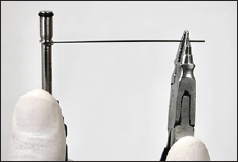
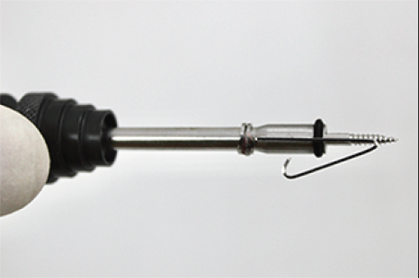
Step 1: Use the stainless steel wire and wind two to three helices around the implant driver (Figure 1).
Round Helices Around the Implant Driver.
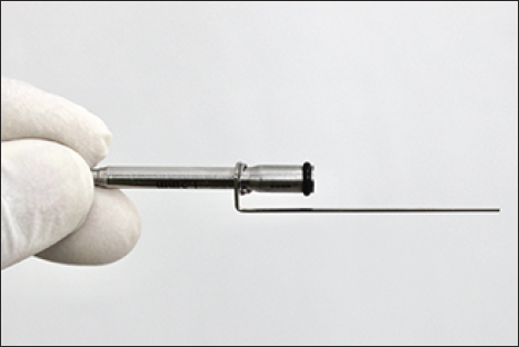
Step 2: The first bend: Bend the wire at a 90° angle toward the cutting edge of the IZC screw (Figure 2).
The First Bend.
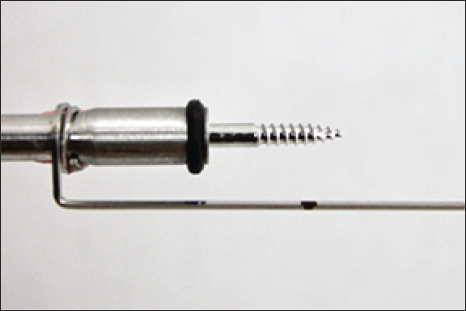
Step 3: The second bend: This would be at the distance of the total thickness of the cortical bone and the soft tissue.
Cortical bone thickness can be obtained from the CBCT and soft tissue thickness can be obtained using an endodontic file or a periodontal probe. 3 Adding the two will give us the exact distance the screw has to be driven at a 90° to the bone. When this is achieved, the operator then needs to start angulating the screw (Figure 3) (cortical bone thickness: 1.44 ± 0.39 in adolescents, 1.58 ± 0.34 in adults). 2
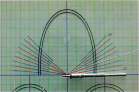
Step 4: Mark the obtained distance from the cutting edge of the screw toward the implant driver and make the second bend measuring the angle adjacent to your desired angulation (Figure 4). For example, if the desired angulation is 70°, the adjacent angle would be 90°–70° = 20° (Figure 5). 1
Marking of Total Distance of the Gingival and Cortical Bone Thickness to Make the 2nd Bend.
Measuring the Adjacent Angle Using a Symgrid.
Correct Angulation of the IZC Screw as Given by Lin J Robert. 1
Step 5: Make a tag arm at the end part of the wire (Figure 6).
The Second Bend.
Clinical Implication
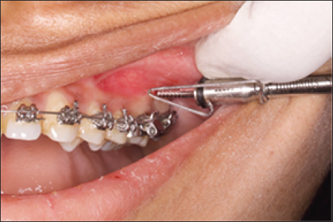
As the guide is attached to the implant driver and the screw is driven first at the 90° angle, the second bend will give it a stop as soon the operator has driven through the cortical bone and the soft tissue. This point is the purchase point in the cancellous bone.
This stop then indicates that the operator needs to start angulating the screw (Figure 7(a)).
Clinical Implication: First Bend.
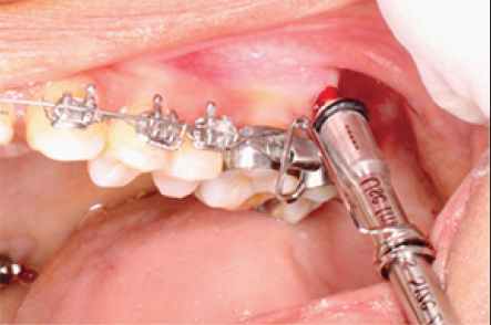
Retract the appliance and start the angulation of the screw. After a few more turns, push the appliance back and check if the angulated arm is parallel to the first molar (Figure 7(b), 7(c)).
Clinical Implication: Second Bend.
Post Operative Radiograph.
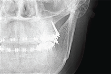
Once it is parallel to the first molar, the operator has achieved the desired angulation.
Hence, using this simple guide, the operator can increase the accuracy of infra zygomatic crest screw placements.
Stability and accuracy of the guide can be evaluated with further researches in the future.
Footnotes
Declaration of Conflicting Interests
The authors declared no potential conflicts of interest with respect to the research, authorship and/or publication of this article.
Funding
The authors received no financial support for the research, authorship and/or publication of this article.
Ethical Approval
Ethical committee clearance and patient consent is not required for this article, as it is not a clinical study.