
Abstract
Introduction:
The study was conducted to assess the stress and displacement effects of a mini-implant supported k-loop on the maxillary dentition for distalization with 3-dimensional (3D) finite element stress analysis.
Materials and Methods:
A 3D model of the maxilla with all teeth, periodontal ligament, bone, mini-implants, brackets, and archwire was used in this study. The analytic model used in this study like brackets, wire, K-loop, and mini-implants was developed using a reverse engineering technique extracting the dimensional details of the physical parts using precision measuring instruments.
Results:
The distobuccal movement on the first molar and second molar were 0.26864 mm and 0.00833 mm, respectively. A total of 0.25 mm intrusion movement was seen on distal cusp of the first molar and 0.14 mm extrusion movement seen on mesial cusp of the first molar. A total of 0.25 mm and 0.00260 mm intrusion movement was seen on the distal cusp of the first molar and second molar, respectively. A total of 0.14 mm and 0.00324 mm extrusion movement was seen on the mesial cusp of the first molar and second molar, respectively.
Conclusions:
There was a large amount of distal displacement of the first molar, also negligible amount of tipping of the first molar and mesial movement of first premolar.
Abbreviations
ANSYS: Analysis System Software
CT: Computerized Tomography
FEA: Finite Element Analysis
FEM: Finite Element Method
MIMICS: Materialize Interactive Medical Image Control System
MPa: Megapascals
PDL: Periodontal Ligament
Introduction
Management of a patient having Angle’s Class II malocclusions with crowding in maxillary anterior region and excessive overjet involves moreover 2 maxillary arch premolars extraction or else distalization of maxillary posterior teeth. During the last decades, a large number of intraoral and extraoral distalizing appliances and techniques that reduce or eliminate the necessity for patient obedience have been introduced from various authors in edict to precise Angle’s Class II malocclusion.1, 2 Angle’s Class II malocclusion affects approximately 33% of orthodontic patients comprising of both dental and skeletal deviations from the established average. 1 Traditionally, Cervical pull headgear is used for maxillary molars distalization which depends on patient amenability.1-3 Pendulum appliance, 2 magnets, 4 Japanese NiTi coil, 5 super elastic NiTi wires, 6 Open Coil-Jig, 7 K-loop, 8 fixed piston appliance, 9 distal jet, 10 Keles slider, 11 modified slider, 12 and MGBM system 13 are the various intraoral distalization appliances which are nondependent on patient cooperation. 14
Earlier case reports and researches have proven that extraoral cervical pull involves substantial patient obedience to get efficacious results.1-3 Thinking of the other side, the less dependency on cooperation of patients and comfortable use are amid the benefits of the distal jet. 10 But frequently, distalization involves tipping and rotation movement of the molar accompanying the considerable anchorage loss. Recently, many intraoral distalizers have been tried with mini-implant anchorage such as the TopJet, 15 modified C-palatal plate, 16 and mini-screw supported EZ slider auxiliary 17 for bodily molar distalizer. Besides providing absolute anchorage, mini-implants have clinical advantages such as versatility of placement at anatomic locations, economical, and easy to place with minimal trauma. In 1995, Dr Kalra introduced the distalizing appliance “K-loop,” which allows the clinician the actual resistor and supervision of moment-to-force ratio. 10
Cephalometric clinical researches11, 12 have shown that there are chances of inaccuracy when performing measurements on radiographs and cephalometric measurement. 15 The finite element analysis (FEA) engineering tool is developed to overcome these challenges. In the field of engineering, the finite element method (FEM) is used for evaluation of stress and strain. This innovation enables to record and evaluate the stress and strain in living structures due to internal and external forces. Till date, none of the FEM study was conducted on K-loop to evaluate teeth movement tendencies. Thus, the current research was accompanied to mimic the mini-implant supported K-loop and to investigate teeth movement tendencies by FEA.
Material and Methods
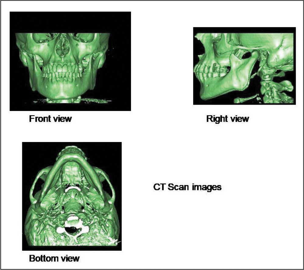
Ethical approval from relevant committee was obtained. The research was done using a 3-dimensional (3D) FEA expending a spiral computerized tomography (CT) machine. The CT scan of the model was done by a SH spiral CT scan machine. CT scan of the skull is shown in Figure 1. A 3D model of the upper jaw presented with all permanent teeth, bone, periodontal ligament (PDL), arch wire, brackets, and mini-implants, was used in the present research. The analytic model presented in present study like mini-implants, K-loop, wire, and brackets were established using reverse engineering method removing the dimensional particulars of the physical fragments using meticulousness determining tools.
CT Scan Model.
The skull CT scan image was procured and later with the use of mimics software, image was converted to the DICOM data, and later into geometric model. The cloud data points and lines were transferred to RAPID FORM in the STL format. The area of interest required for study, that is, maxilla was extracted from the complete skull.
The MIMICS data was processed in RAPID FORM software to fabricate the surfaces, which further transferred in IGES format to HYPERMESH. The anatomic model consisting of surface data was utilized to fabricate the maxillary teeth (geometric model) having the morphology and dimensions described in textbook of Wheeler’s using software ANYSYS. An average thickness of 0.2 mm of the PDL was presumed and created round the roots of all teeth.
Mini-implant (length, 6 mm; diameter, 1.4 mm; DENTOS) was entrenched between roots of maxillary right first molar and right second premolar.
The fabrication of K-loop was done with 0.017″ × 0.025″ Beta Titanium wire. The loop was placed in auxiliary molar tube of permanent maxillary right first molar and engaged with maxillary right permanent first premolar bracket reinforced with mini-implant through 0.010 stainless steel ligature wire.
With the help of software HYPERMESH, present geometric model further transformed into finite element model, which is illustrative of the geometric model in expressions of finite number of nodes and element. This process is known as discretization. For a 3D examination, the finite elements may be rectangular prisms, hexahedron, or tetrahedron. In this study, we have used the finite number of small tetrahedron parts. Each such small parts is also called element which is connected to other parts at the corners called nodes. This model which is structured as elements and nodes and is called finite element model. In the present study, the final model had 573,897 tetrahedral elements and 120,551 nodes. The finite element model with full dimensional wire, brackets, K-loop and mini-implants buccal, and occlusal look as shown in Figure 2.
Finite Element Model With Brackets Full Dimensional Wire, K-Loop, and Mini-Implants Buccal and Occlusal View.
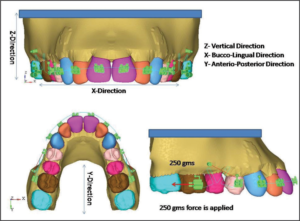
The 3D model was gathered along with the x-axis, y-axis, and z-axis corresponding to the buccolingual direction, the anteroposterior direction, and the vertical direction, respectively. A positive x-value, y-value, and z-value was distinct as the buccal direction, distal direction, and the apical direction, respectively. The movements of the teeth were estimated by applying the x, y, and z coordinates at the distopalatal cusp, mesiobuccal cusp, and mesiobuccal root apex of the maxillary molars, respectively. The present model was reserved posterior border of the maxillary bone and at the nasal floor side in all directions. For this model, the boundary condition requires to be distinct so that all movements of the model are controlled while the load is acting to avert the model from body motion. The upper part, posterior surface, and base of the maxilla were used as a boundary condition.
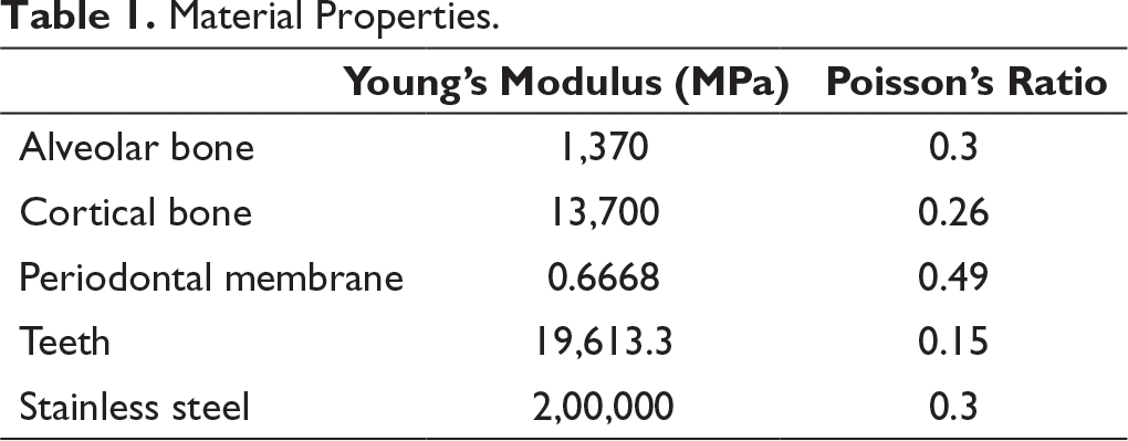
Material Properties.
For the present model, FEA was recognized by smearing 200 g force. By utilizing the FEM, the preliminary vertical dislodgment of the posterior teeth and the Von Mises stress dispersal along the root surface were evaluated. To define tipping movements accurately, vertical translations of the nodes, possessing the same coordinates in each model at the root apexes and the cusp tips, were evaluated, and superimpositions were used.
Displacement and stress were offered as variable color bands, which signified dissimilar magnitude. Red color column of the spectrum indicated the highest level trailed by different shades of orange, yellow, green, blue, while dark blue represented the lowest level.
Computer Configuration Used
Hardware
A computer model having an Intel core i3 with 2.1 GHz, 2GB of RAM, 2GB Graphics card, 320 GB hard Disc, 17″ Monitor was used for the present study.
Software
Materialize Interactive Medical Image Control System (MIMICS 8.11) is a medical modeling software utilized for the segmentation and visualization of skull CT images.
The software helped to renovate CLOUD DATA POINTS to SURFACES. The transformed SURFACES were stowed in IGES format.
Software used to construct finite element model from geometric model.
Results
The inference of a research is termed as post-processing. The stresses were intended and offered in bands of various colors, particular colors epitomized altered stress levels in the distorted state. Red color column of spectrum designates the highest principal stresses and succeeding colors like orange, yellow, green, and blue represent descending stress levels.
The results were accomplished as dissemination of stresses and displacement of the teeth and PDL. The Von Mises stresses were in megapascals (MPa) and displacement was in millimeters.
Von Mises Stress Contours of Periodontal Ligament
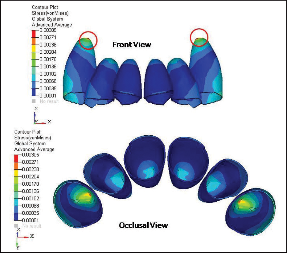
Anterior Teeth
The highest amount of Von Mises stress was perceived at apical area of canine (0.00305 MPa). However, middle 1/3rd of all the teeth roots displayed minimum stress values (0.00001 MPa) (Figure 3).
Von Mises Stress Contours of Periodontal Ligament of Anterior Teeth.
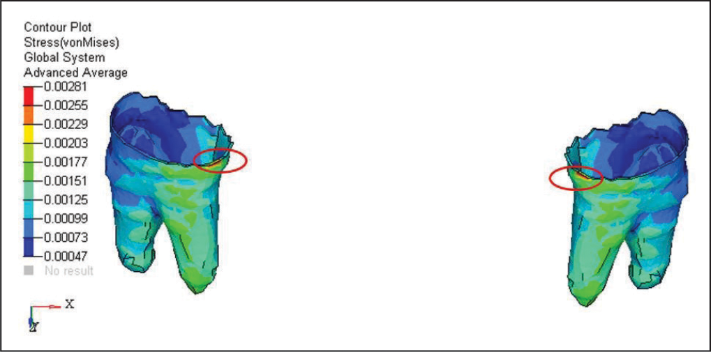
First Premolar
The highest amount of Von Mises stress was detected in the buccocervical region of first premolar teeth (0.00281 MPa). However, middle 1/3rd of all the teeth roots displayed minimum stress values (0.00047 MPa) (Figure 4).
Von Mises Stress Contours of Periodontal Ligament of First Premolar.
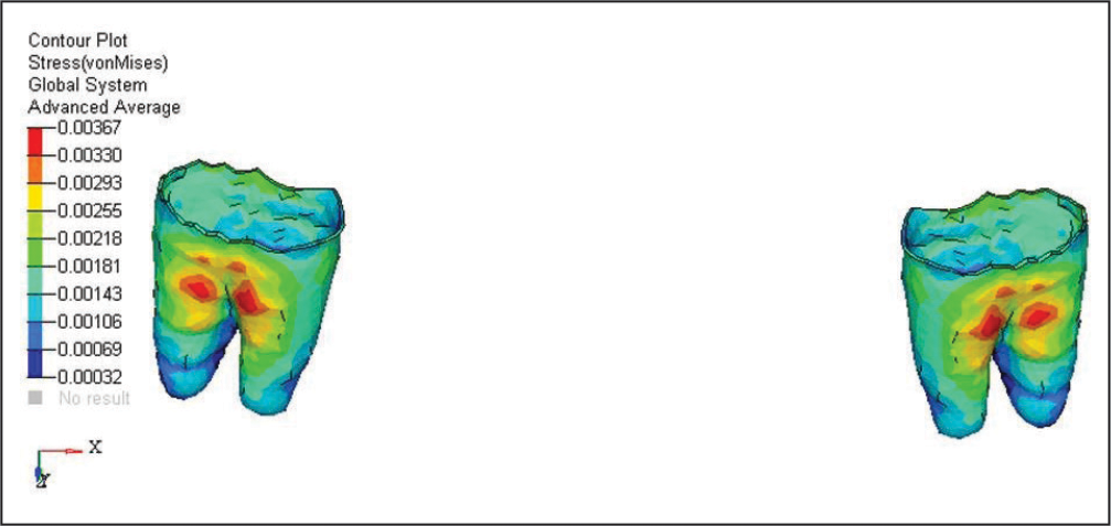
Second Premolar
The highest amount of Von Mises stress was perceived at furcation area of second premolar teeth (0.00367 MPa). However, the apical region of roots showed low stress values (0.00032 MPa) (Figure 5).
Von Mises Stress Contours of Periodontal Ligament of Second Premolar.
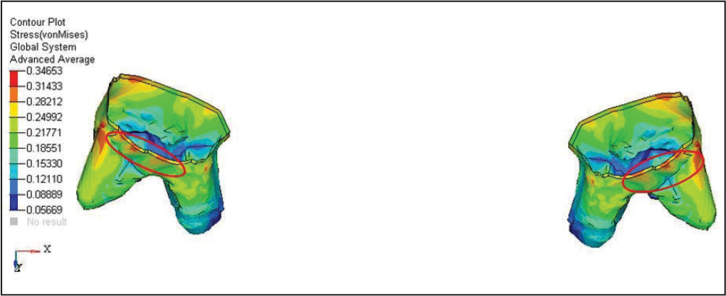
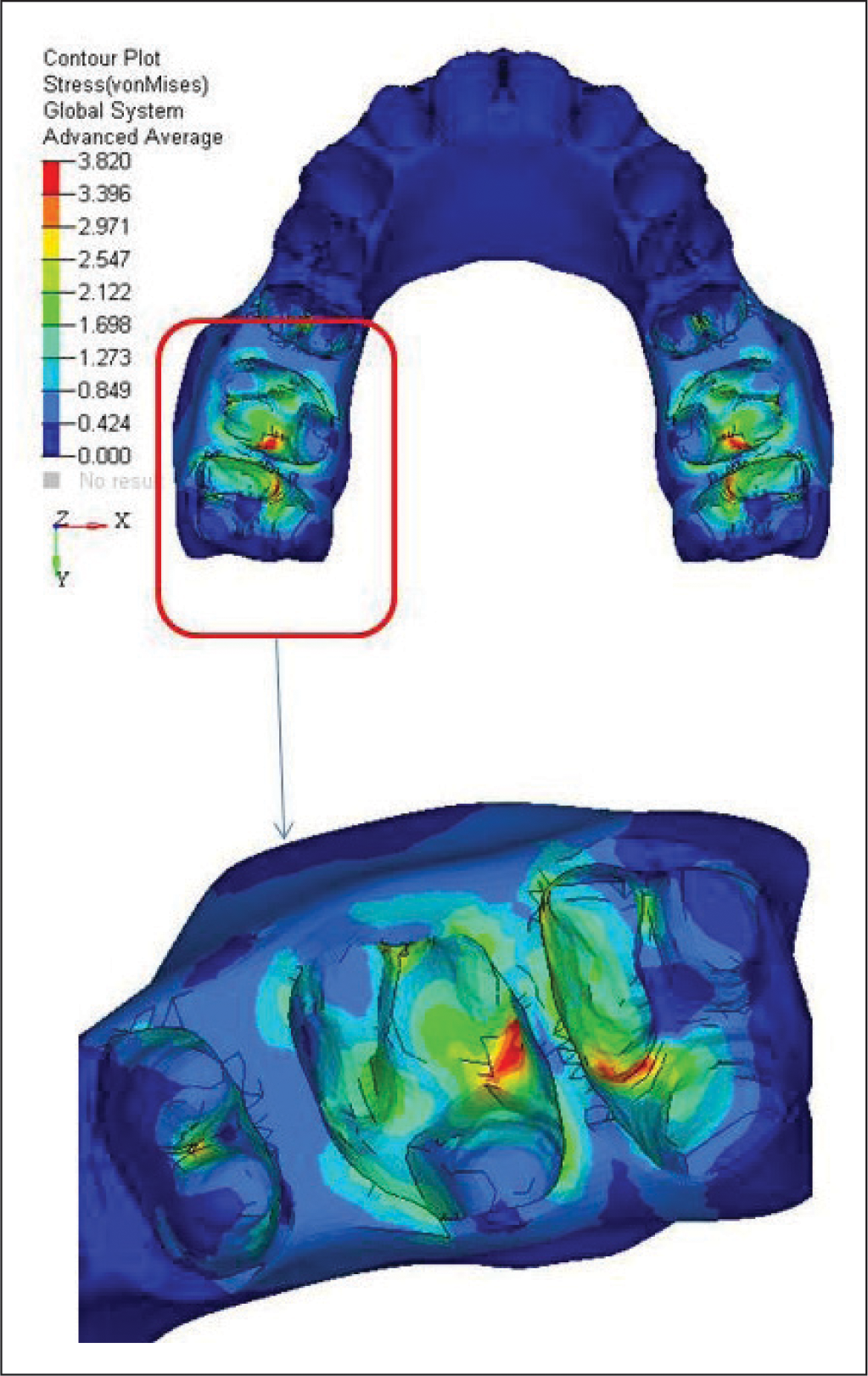
First Molar
The highest amount of Von Mises stress was noticed in the buccocervical region of first molar teeth (0.34653 MPa). However, apical region of distobuccal root showed low stress values (0.05669 MPa) (Figure 6).
Von Mises Stress Contours of Periodontal Ligament of First Molar.
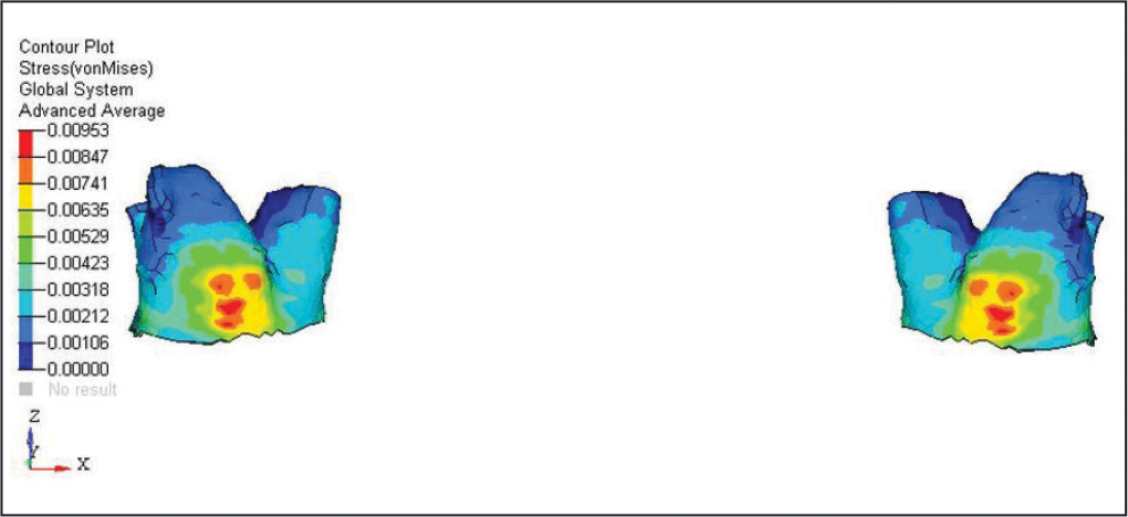
Second Molar
The highest amount of Von Mises stress was perceived at middle third of distobuccal root region of first molar teeth (0.00953 MPa). However, apical region of distobuccal root and mesiobuccal root showed low stress values (0.00106 MPa) (Figure 7).
Von Mises Stress Contours of Periodontal Ligament of Second Molar.
Cortical Bone of Maxilla
The highest amount of Von Mises stress was observed at buccal alveolar cortical bone of first molar region (19.94370 MPa). However, the anterior alveolar bone showed no stress values (Figure 8).
Von Mises Stress Contours of Cortical Bone of Maxilla.
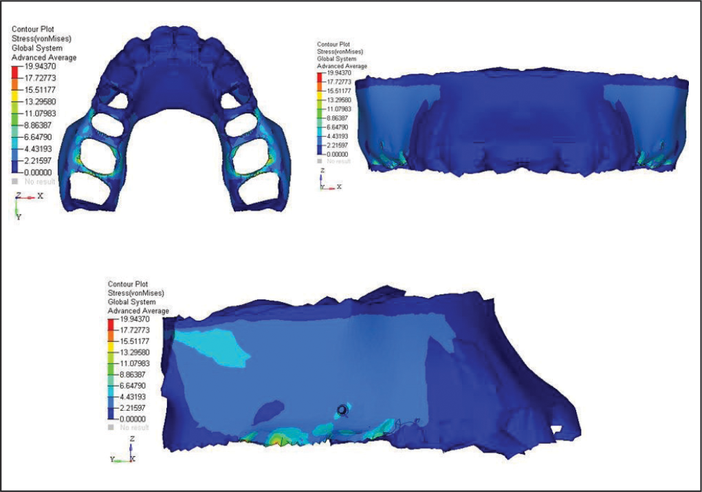
Cancellous Bone of Maxilla
The highest amount of Von Mises stress was perceived at distal interradicular bone of first molar and mesial interradicular bone of second molar (19.94370 MPa) (Figure 9).
Von Mises Stress Contours of Cancellous Bone of Maxilla.
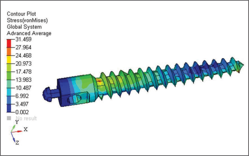
Mini-Implant
The highest amount of Von Mises stress was perceived at mini-implant in cortical bone interface area (31.459 MPa). The minimum Von Mises stress was detected at the apical third area of mini-implant (0.002 MPa) (Figure 10).
Von Mises Stress Contours of Mini-Implant.
Displacement Contours of Teeth as Follows
Anterior Teeth
Overall, a very negligible movements was seen on canine.
In x direction and y direction, no movements was seen.
In z direction, 0.00133 mm extrusive movement was seen (Figure 11).
Displacement Contours of Anterior Teeth.
First Premolar
Overall, a very negligible movement was seen on the first premolar.
In x direction, very mild mesiopalatal movement of the first premolar was seen (0.00067 mm).
In y direction, root movement = 0.003 mm and crown movement = 0.006 mm which was very negligible due to indirect anchorage from mini-implant.
In z direction, 0.0005 mm intrusion movement was seen on the first premolar (Figure 12).
Displacement Contours of First Premolar.
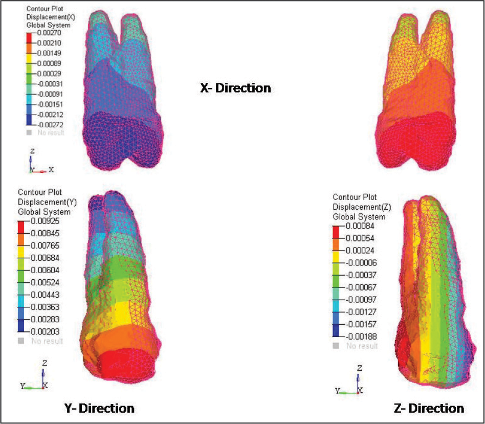
Second Premolar
Overall, a very negligible movement was seen on the second premolar.
In x direction, very mild mesiopalatal movement of second premolar was seen (0.00270 mm).
In y direction, root movement = 0.002 mm and crown movement = 0.009 mm.
In z direction, 0.0008 mm intrusion movement was seen on the second premolar (Figure 13).
Displacement Contours of Second Premolar.
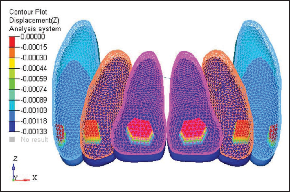
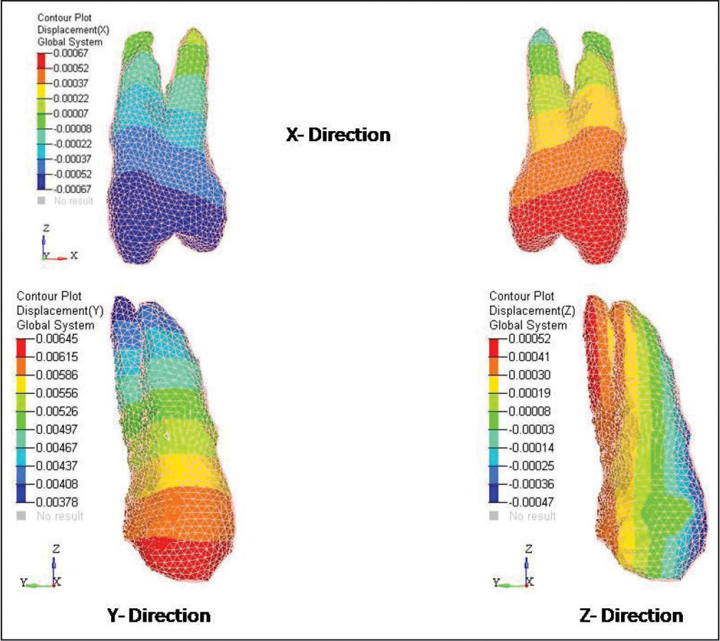
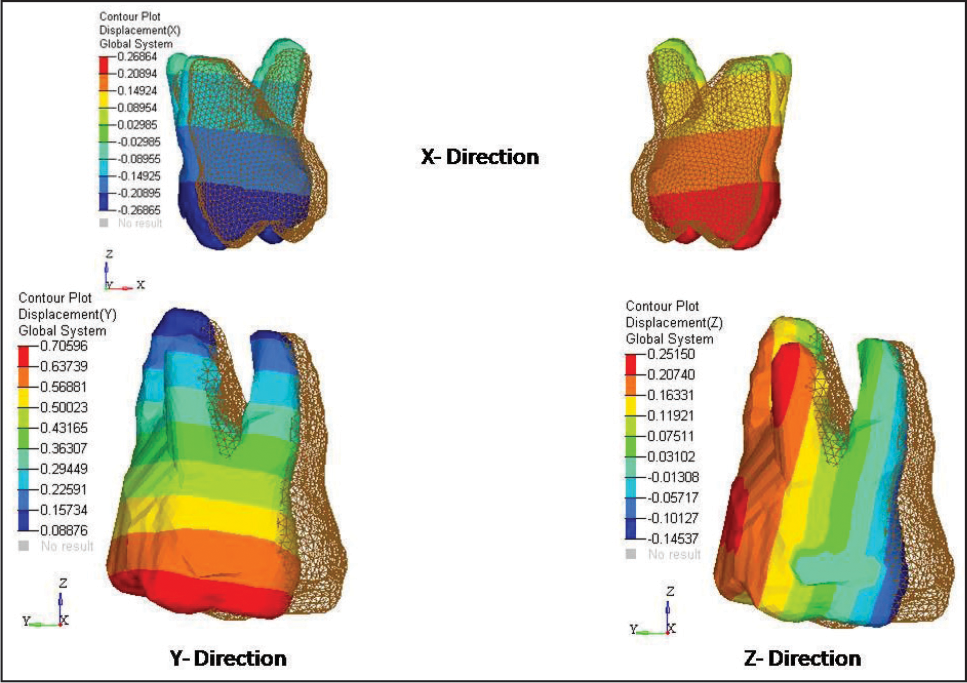
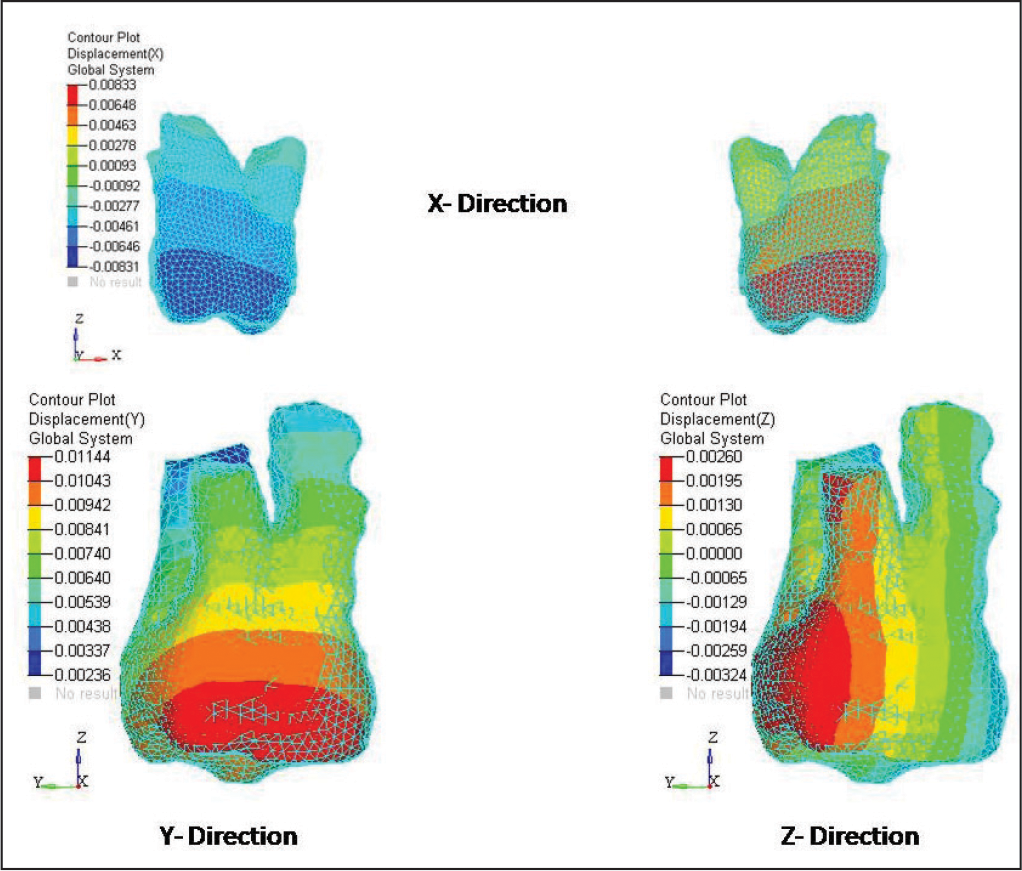
First Molar
In x direction, very distobuccal movement of the first molar was seen (0.26864 mm).
In y direction, root movement = 0.0088 mm and crown movement = 0.706 mm.
In z direction, 0.25 mm intrusion movement was evident on distal cusp of maxillary first molar and 0.14 mm extrusion movement seen on mesial cusp of the first molar (Figure 14).
Displacement Contours of First Molar.
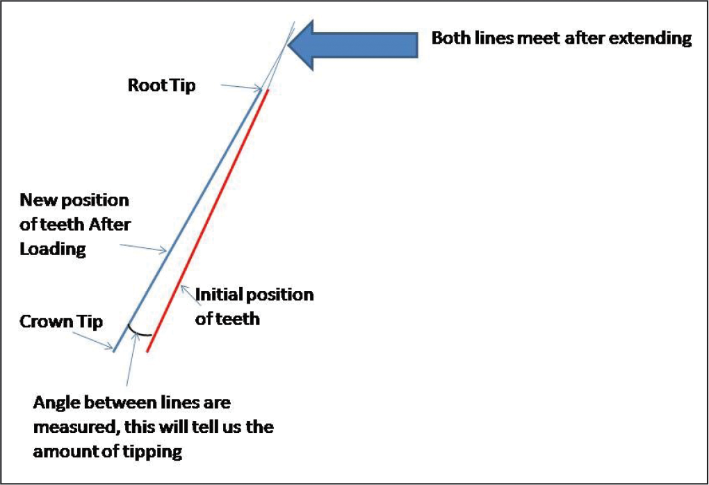
The first molar tipping (inclination) is 2° and measurement technique as shown in Figure 15.
The First Molar Tipping (Inclination) Measurement Technique.
Second Molar
In x direction, very negligible distobuccal movement of the second molar was seen (0.00833 mm).
In y direction, root movement = 0.002 mm and crown movement = 0.011 mm.
In z direction, 0.00260 mm intrusion movement was seen on distal cusp of the second molar and 0.00324 mm extrusion movement seen on mesial cusp of the second molar (Figure 16).
Displacement Contours of Second Molar.
Discussion
In present days, every clinician tries to opt for the nonextraction treatment plan in patients having class II malocclusion. The orthodontic management for patients having class II malocclusions with no major skeletal discrepancies, distalization is a commonly used treatment modalities by clinicians and practitioners. In the literature, the use of various compliance-free intraoral maxillary molar distalizing appliances is evident.2, 4-12 Many studies have showed it remains a significant challenge for maxillary molar distalization to achieve distal bodily movement of the maxillary first molars with minimal distal-crown tipping and minimal rotation.16-18 During maxillary first molar distalization, a signification challenge remains in prevention of mesial tipping, mesial movement, and extrusion of maxillary first premolars.17, 18
K-loop was introduced by Varun Kalra in 1995, which was fabricated according to Charles Burstone’s certain biomechanical principles. It has the ability to distalize maxillary first molar with total bodily control. 8 In this study, mini-implant was used as an indirect anchorage to prevent mesial anchorage loss during distalization.
In the present study, 0.00133 mm extrusive movement was seen on the anterior teeth, which was very negligible. On the first premolar and second premolar, the 0.0005 mm and 0.0008 mm intrusion movement was observed, respectively. Due the buccally acting forces, the mesiopalatal movement of first premolar and second premolars was seen, which was 0.00067 mm and 0.00270 mm, respectively. In contrast, distobuccal movement on the first molar and second molar was 0.26864 mm and 0.00833 mm, respectively. A total of 0.25 mm intrusion movement was seen on first molar on distal cusp and 0.14 mm extrusion movement seen on mesial cusp of maxillary first molar. A total of 0.25 mm and 0.00260 mm intrusion movement was seen on the distal cusp of maxillary first molar and second molar, respectively. A total of 0.14 mm and 0.00324 mm extrusion movement was seen on the mesial cusp of first and second molar, respectively.
In previous studies,19-21 it was stated that additional 9° inclination of molar was evident with other implant-assisted distalization appliances. But lately, Nur et al 22 stated that the zygoma-gear appliance anchored with titanium plates was used for bilateral maxillary molar. It showed amount of the maxillary molar inclination to 3.30° ± 2.31°. In the present study, the molar inclination was only 2° because K-loop effectively controls the moment-to-force ratio. 8
To control mesial anchorage loss for K-loop, Nance palatal button is required. 8 In the present study, Nance palatal button was eliminated and the anchorage was reinforced by mini-implant. In this FEA study, there was no mesial movement of anterior teeth, but on the first premolar and second premolar the 0.003 mm and 0.002 mm root movement and 0.006 mm and 0.009 mm crown movement were found, respectively. Overall, the movements were very negligible, but according to previous studies some anchor loss was observed with indirect skeletal anchorage systems.23, 24
As compared to other distalizing appliances, K-loop is easy for fabrication, placement, and activation, thus eliminating the need of cumbersome wire bending. K-loop with mini-implant is better substitute for bulky and complex designed distalizer such as TopJet, C-palatal plate, and EZ slider. Mini-implants have clinical advantages such as versatility of placement at anatomic locations, economical, and easy to place with minimal trauma.
Shashidhar et al 11 evaluated the skeletal and dentoalveolar effects of maxillary first molar distalization with K-loop appliance with that of pendulum group. They concluded that no noteworthy vertical variations were perceived during distalization. Further, they concluded that the K-loop had advantage of being simple yet effective in controling the moment-force ratio to yield all types of tooth movements and also necessitate minimal patient cooperation.
This present study has some limitations, such as only conniving initial tooth displacement with FEA. Variances in mechanical properties between biological tissues and virtual models, elastic recovery force of archwires over time, and occlusal force are the important clinical factors which were not applied.
Conclusion
In conclusion, the outcome confirmed that the mini-implant-anchored K-loop can attain absolute anchorage and distalize maxillary first molars successfully. Absolute anchorage control was conveyed by using mini-implants during the distalization of molars and the insignificant amount of mesial movement of first premolar. The extrusion movement was seen on mesial cusp of first molar with negligible amount of tipping of the first molar. We propose this new method can be implemented in nonextraction class II treatment in preference to intraoral and extraoral distalization appliances.
Footnotes
Declaration of Conflicting Interests
The authors declared no potential conflicts of interest with respect to the research, authorship, and/or publication of this article.
Funding
The authors received no financial support for the research, authorship, and/or publication of this article.
Statement of Informed Consent and Ethical Approval
Necessary ethical clearances and informed consent was received and obtained respectively before initiating the study from all participants.