
Abstract
Background and Objectives:
This study was conducted to determine the effective method to torque the incisor with thermoplastic aligner using a three-dimensional (3D) finite element method.
Materials and Methods:
Three finite element models of maxilla and maxillary dentition were developed. In the first model, thermoplastic aligner without any auxiliaries was used. In the second and third models, thermoplastic aligner with horizontal ellipsoid composite attachment and power ridge were used, respectively. The software used for the study was ANSYS 14.5 FE. A force of 100 g was applied to torque the upper right central incisor. The resultant force transfer, stress distribution, and tooth displacement were evaluated.
Results:
The overall tooth displacement and stress distribution appeared high in the model with power ridge, whereas the root movement was more in the horizontal ellipsoid composite attachment model. The model without any auxillaries produced least root movement and stress distribution.
Conclusion:
Horizontal ellipsoid composite attachment achieved better torque of central incisor than the model with power ridge and model without any auxillaries.
Introduction
Orthodontics has been involved with biomechanics such as edgewise appliance, Begg’s light wire differential force technique, preadjusted edgewise appliance, tip edge, etc. Simultaneously, the thirst to develop invisible treatment modalities also grew, which include lingual orthodontics and thermoplastic aligner systems. Both lingual orthodontics and aligner systems had undergone initial enthusiastic phase and later lag phase. The lag phase was due to a number of limitations and difficulties that the appliance faced. Now, we are in learning, research, and developing phase that would help us to treat patients with invisible treatment modalities in a better way.
Torque control of anteriors should be monitored by the clinician from the very beginning of the treatment because if the torque control is lost, it is difficult to regain back the control. Being associated with complex biomechanics, we need a thorough understanding of the torquing action of thermoplastic aligners. Torque is routinely established in the bracket system by creating a couple, established with equal and opposite moments, within the bracket to wire complex. In thermoplastic aligners, torque is accomplished by creating a force-inducing projection in the aligners or by placing attachments on tooth surface. 1
Even though the movement of teeth with thermoplastic appliances has been clearly documented, the biomechanical effects of these appliances have been evaluated only in a few studies. The aim of the present FEM study is to evaluate the biomechanical effects of torquing on upper central incisor with thermoplastic aligner—a comparative three-dimensional finite element (FE) study with and without auxillaries.
Materials and Methods
The FE models were generated for torquing upper incisor through thermoplastic aligners with and without auxillaries, and the study was carried out using the FE software (ANSYS 14.5 FE software).
In aligner-based tooth movement, an intentional, predetermined difference in the tooth position between the aligner and tooth is programmed in each treatment stage, using a cast or virtual model setup. As per the protocol, in this study, we wanted to torque the root of upper central incisor with a deflection of 0.15
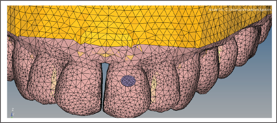
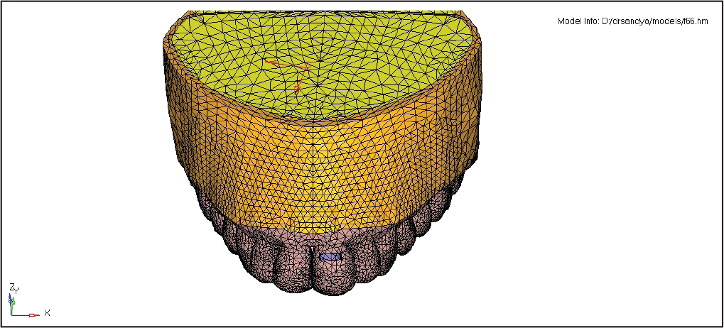
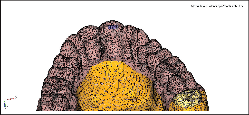
For the study, three FE models of human maxilla and maxillary dentition were constructed as follows:
The first model consisted of thermoplastic aligner without composite attachment. The second model consisted of thermoplastic aligner with composite attachment on the upper incisor. The third model had the thermoplastic aligner with power ridge on the upper incisor.
For simulation of the involved structures, their physical characteristics were determined in the following manner:
Properties Assigned to the Alveolar Bone, Tooth, Composite Attachments, and Plastic Aligner.
Mathematical models represent the biological properties of the teeth, and also the periodontia were constructed. For simulation of teeth, alveolar bone, composite attachments, and thermoplastic aligner—a linear elastic, isotropic, and homogenous behaviour was assumed and mechanical properties were obtained from previous studies (Table 1). For periodontal ligament, a nonlinear elastic, isotropic, and homogenous behaviour was assumed, with a stress–strain function based on the data from previous studies.
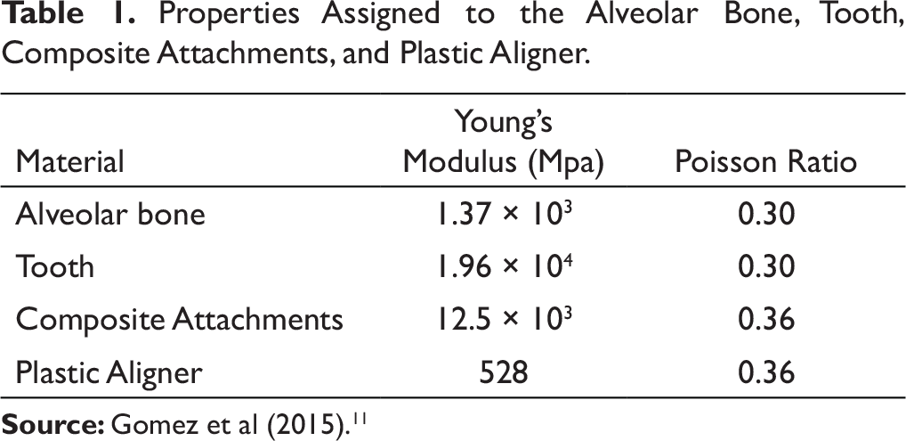
The horizontal ellipsoid composite button (Figure 1) was attached to the tooth for torquing movement similar to the Invisalign Smart force features and Mareike Simon et al. 6 The dimension of composite button was 3 mm in height, 2 mm in width, and 1 mm in (thickness–depth) prominence, and the same was simulated in the study.
Horizontal Ellipsoid Composite Attachment.
Power ridges (Figures 2 and 3) are engineered corrugations of thermoplastic aligners placed at specific locations, such as near the gingival margin of labial aspect and incisal edge of lingual aspect of the tooth, and the same was simulated in the study.
Power Ridge: Labial Aspect.
Power Ridge: Lingual Aspect.
For the root torque of 0.15 mm, force of 100 g was assumed and applied to the incisors in accordance with Wolfram Hahn et al. 14 The forces measured during torquing with a deflection of 0.15 mm tend to be close to the ideal forces stated in the literature (Proffit, 2000), which is in the range of 50 to 100 g.
In this FE simulation of clinical event, 100 g of force will be assumed and applied to torque incisor with a deflection of 0.15 mm and the biomechanical effects of different parameters of thermoplastic aligner—without any composite attachment, with horizontal ellipsoid composite attachment and inbuilt power ridge was studied.
Thus, with this three-dimensional FE study, force transfer and stress distribution on the supporting structures during torquing of the upper incisors through thermoplastic aligners with and without auxillaries (attachment and power ridge) was studied and compared.
Results
The stress distribution and the amount of torquing took place with the required force applied in three models consisting of maxilla and maxillary dentition with thermoplastic aligners without any auxillaries, horizontal ellipsoid composite attachment, and power ridge on the upper right central incisor picturized under the following headings are as follows and presented in Table 2:
overall displacement; displacement view 1; displacement view 2; aligner stress; tooth vector displacement; root vector displacement; overall stress; cortical stress; cancellous stress; periodontal stress; and teeth stress.Tooth Displacement and Stress Distribution.
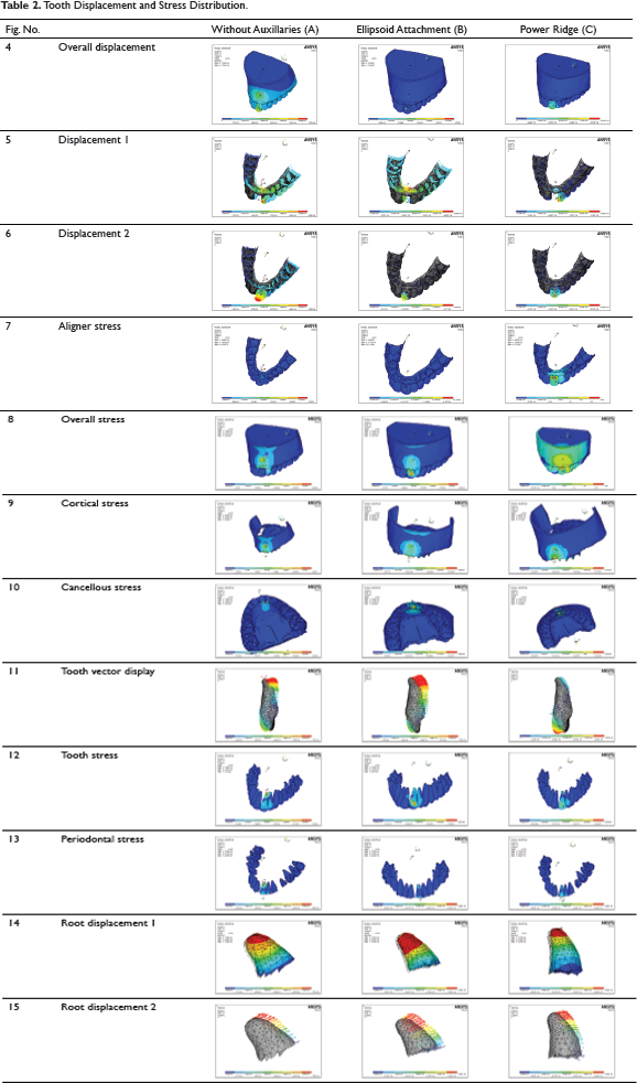
Table 3 shows that root displacement with ellipsoid arrangement was little more when compared to the other two arrangements.
Comparison of Incisor Root Displacement.
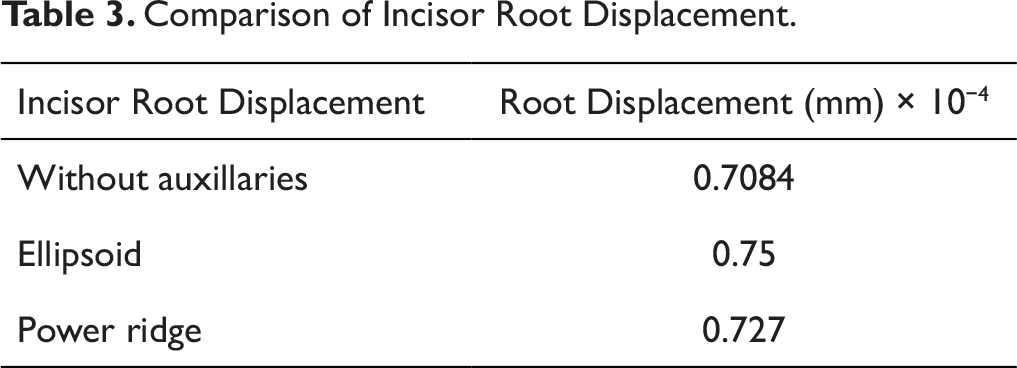
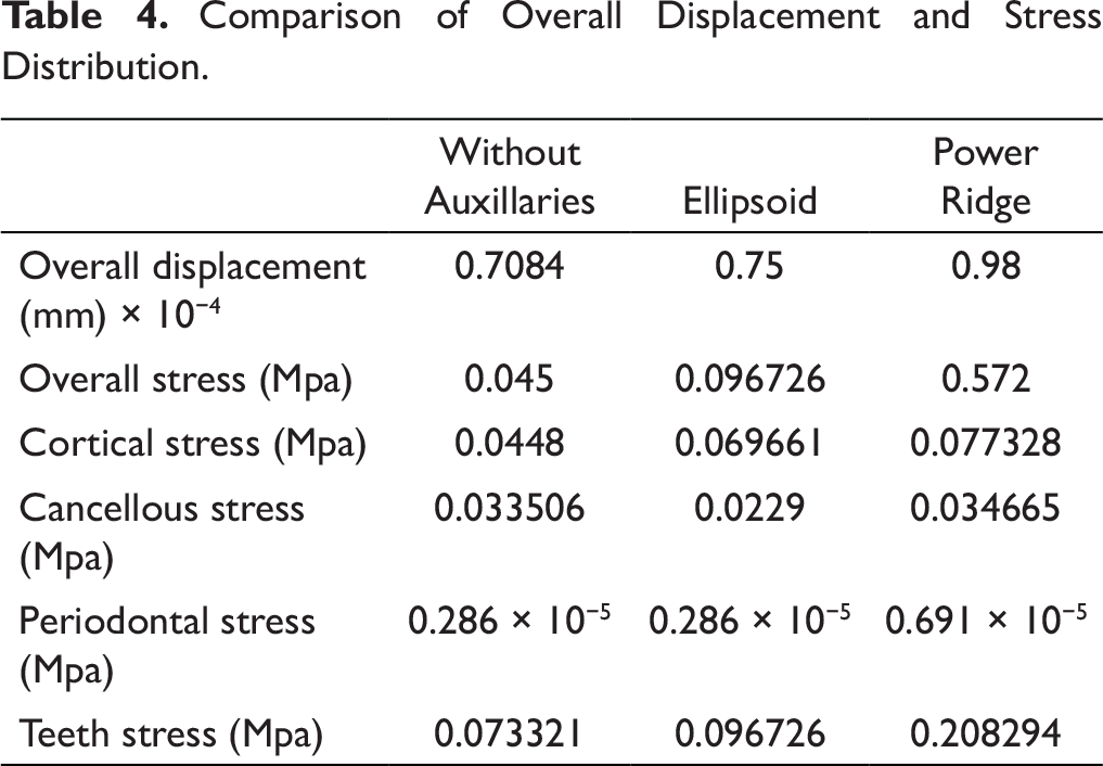
Table 4 shows overall displacement and stress distribution of various arrangements. The power-ridge arrangement shows maximum displacement and stress in the crown region when compared to the root region.
Comparison of Overall Displacement and Stress Distribution.
Discussion
It was decided to conduct an FEM study because, with FEM, it is possible to anticipate the tissue responses to orthodontic mechanics applied. It represents a noninvasive, accurate method that provides quantitative and detailed data regarding the physiological responses occurring in tissues, such as the periodontal ligament and the alveolar bone. 2
In orthodontics, the meaning of torque is different clinically and biomechanically. Clinically, the “torque” is the third key of the occlusion, described by Andrews as the inclination of the dental crown anteroposteriorly in the frontal teeth and transversal in the backward teeth. Biomechanically, the torque is represented by the torsion of a rectangular archwire in the bracket slot. 3
The earliest forms (first generation) of aligner systems were solely reliant on the aligner to achieve their results. No auxiliary elements were incorporated. As aligner systems developed, the second-generation manufacturers began to encourage the use of attachments to improve tooth movement. In the third generation of aligners, efforts to improve the results and achieve better control of tooth movements with aligner appliances, have been made by altering the way aligners deliver force. Attachments were placed automatically by the manufacturer’s software where extrusions, derotations, and root movements were required. 4
Align Technology’s Power Ridge is a “twist” of the aligner surface designed to maintain a perfect fit of the aligner at the gingival margin, controlling the force couple and effectively spinning the tooth around its center of resistance. The twist in the aligner material does not affect its uniform thickness, avoiding unwanted intrusion from the “watermelon seed effect,” in which distortion of the gingival edge moves it away from the tooth surface and thus concentrates force in the occlusal region. 5 Castroflorio et al 5 have performed a retrospective study to test the efficiency of Align Technology’s Power Ridge in controlling the buccolingual inclination of upper incisors. They found that differences between their virtual and actual measurements were insignificant, confirming the accuracy of the Invisalign ClinCheck prescriptions, that is, power ridge is efficient in torque expression. 5
The results of present FEM study show that the model with horizontal ellipsoid composite attachment produced better root movement when compared to models with power ridge and without any auxillaries. This could be because of the transfer of both force and moment to the center of resistance of the tooth with ellipsoid attachment, resulting in root movement along with displacement. In case of power ridge, forces cancel out each other, resulting in crown tipping movement, and the moment was transferred to the center of resistance causing root rotation. In the model without any auxillaries, the vector of root displacement was less when compared to other two models because of the less efficient force transfer. The overall displacement with ellipsoid attachment was 0.75 × 10⁻⁴ mm, and the root movement was also 0.75 × 10⁻⁴ mm.
Simon et al 6 found that initial mean moment and amount of achieved torque movement with power ridges and ellipsoid attachments were 7.9 Hmm/6.7 Nmm and 51.5%/41.9%, respectively. This is in contrast to the present study, which showed that the difference between the amount of root movement achieved with ellipsoid attachment was more by 0.3 × 10⁻⁴ mm. At the same time, overall displacement was more with power ridge by 0.23 × 10⁻⁴ mm. This may be attributed to the crown tipping movement that took place due to the power ridge.
Previous studies have shown that horizontal ellipsoid 6 and rectangular composite attachments can be used for lingual root torque of incisors. To achieve predictable tooth movements, we used the horizontal ellipsoid composite attachment that was engineered by Align Technology based on the evidence presented. In the case of ellipsoid attachment, the force along with the moment is transferred to the center of resistance of the tooth, resulting in both lingual root movement and bodily displacement of the tooth. Zhang et al 7 found that with the use of rectangular attachments, the amount of crown movement achieved was more than the root movement and concluded that aligners cause the tooth movement by a tilting motion. When comparing with the above-mentioned study, 7 we can conclude that the horizontal ellipsoid composite attachment may play a better role in achieving lingual root torque because of the force and moment transfer to the center of resistance of the tooth.
Grunheid et al 8 and Kravitz et al 9 evaluated the accuracy of various tooth movements achieved with the aligner by superimposing the predicted and achieved tooth movements. The above-mentioned studies revealed that maxillary incisor had more lingual crown torque, and lingual crown tip was significantly more accurate than labial crown tip and crowns, but anterior teeth roots could not be moved to designated positions. Systematic review by Rossini et al 10 also concluded that clear aligners are effective in controlling posterior buccolingual inclination but not the anterior buccolingual inclination. Gomez et al 11 found a marked tendency of flaring of the buccal and palatal flanks in the aligner segment during distal displacement in their single-tooth FEM model.
The overall displacement with power ridge was 0.98 × 10⁻⁴ mm, and with root movement, it was 0.727 × 10⁻⁴ mm. In the case of power ridge, the force acts on the labiogingival and linguoincisal regions of the tooth, which tends to cancel out each other, resulting only in moment transfer to the center of resistance of the tooth causing lingual root movement. Apart from lingual root movement, because of the force present in the crown region, minimal amount of labial crown movement was also observed. A case report has shown that despite the short clinical crowns of the maxillary laterals, the power ridges proved effective in delivering the moment-to-force ratio needed to keep the teeth tracking within the aligners while delivering torquing vectors of force to these teeth. 12 However, the above-mentioned studies did not do any comparisons with other modes for achieving torque control.
Literature comparing the torqueing movement of incisors in aligners among attachments and power ridges is very limited. The available literature showed that power ridges are more efficient in torque control than attachments.6, 13
The overall displacement in the model without any auxillaries is 0.70 × 10⁻⁴ mm and with root movement was 0.70 × 10⁻⁴ mm. Amount of root displacement achieved in this model without any auxillaries is the least among the three models. This is in accordance with Hahn et al 14 who found that torque movement requires the presence of a force couple acting on the tooth, and in the case of clear aligners, the movement inside each aligner determines that, initially, the aligner does not fit the tooth crown perfectly, and a certain amount of reversible deformation is present at the gingival margins of the aligner. Such deformation prevents the formation of an effective couple and is the reason why torque is difficult to achieve with clear aligners. He also suggested the use of auxillaries such as attachments to achieve torqueing with aligners. 14
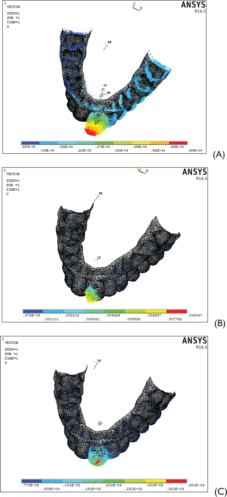
In displacement views 1 and 2 (Figures 4 A-C), the results showed that stress transfer is gradually decreased from central incisors, lateral incisors, and almost nil in the posterior segment, indicating insignificant amount of deflection of aligners in other areas. When comparing overall, cortical, cancellous, periodontal, and teeth stresses, stress distribution is more with power ridge followed by ellipsoid attachment and without auxillaries. We can hypothesize that stress distribution is more with the power ridge because of the force confinement in the crown region and complete moment transfer to the center of resistance of the tooth.
Displacement View 1. (A)Without auxillaries 0.293E × 10−4. (B) Ellipsoid attachment0.499E × 10−4. (C) Power ridge s0.401E × 10−4.
In the present study, the actual aligner models were simulated, and the results showed that the stress distribution to the adjacent site of force application is more and decreases progressively in the nearby areas. There was no notable flaring of aligners, indicating that when aligners covered the entire dentition, they reduced unwanted side effects. Goto et al 15 found it difficult to observe the effect of the attachment in their two-teeth aligner FEM model. In accordance with the above-mentioned studies, it was suggested that the models be modified and the actual aligners replicated by covering the whole dentition. Cai et al 16 suggested that when the thickness of the attachment is greater than 1 mm, it would be difficult to fabricate the aligner.
The results from the FEM concluded that the power ridge arrangement shows maximum displacement in the crown region when compared to the root region due to force arrangement, which creates the tipping of the crown rather than root rotation, whereas, in ellipsoid, maximum root rotation and bodily displacement of tooth was observed. Even though stresses are more with the power ridge, they were within the biological tolerable limit of tooth structures.
Future Results
The model with multiple attachments and various tooth movements are indicated to derive about the behavior of the aligners in a complex treatment process.
Invisalign G4 Enhancements has advocated the use of optimized root control attachment on the buccal aspect and pressure point on the aligner to create a proper force system. This may be validated in the form of future research, whether it can overcome the shortcomings that were observed when, solely, attachments and power ridges were used.
Conclusion
The conclusions that can be drawn from this study are as follows:
All three models were capable of producing root movement. Horizontal ellipsoid composite attachment produced more root movement, followed by power ridge. Model without any auxillaries produced least root movement. Stress distribution with power ridge is more, followed by H = horizontal ellipsoid composite attachment and least stress distribution in the model without any auxillaries. Stress distribution was negligible in the posterior segments. The stress distribution was more in the right segment when compared to the left because the force was applied to the right central incisor. The flaring or deflection of the aligner was not noticed in the maxillary dentition.
Footnotes
Declaration of Conflicting Interest
Funding
The authors received no financial support for the research, authorship, and/or publication of this article.
Statement of Informed Consent and Ethical Approval
Necessary ethical clearances and informed consent was received and obtained respectively before initiating the study from all participants.