
Abstract
Introduction:
In the last decades the application of the Finite Element Methodology (FEM) has become popular. It can calculate stresses and displacement in complex structures and can anticipate the tissue responses to orthodontic mechanics applied for treating different malocclusions. This study evaluated and compared the stress patterns and teeth displacement with application of 450g of intrusive force bilaterally on maxillary posterior segment utilizing a conventional old method, High-Pull Headgear (HPHG) and a newer method, Infrazygomatic Crestal Bone Screw (IZC-BS) using 3D-FEM.
Method:
A 3D-FEM model of the craniomaxillary segment with maxillary teeth was reconstructed from the Cone Beam Computed Tomographic image of a patient with class II div I malocclusion on class II skeletal base with anterior open bite and 450g of intrusive force was applied bilaterally on maxillary posterior segment utilizing HPHG and IZC-BS and stress patterns and teeth displacement were studied and compared.
Result:
Von Mises stresses on Zygomaticomaxillary, Zygomaticotemporal and Pterygomaxillary sutures and surface landmarks on maxillary, zygomatic, temporal and sphenoid bones were more pronounced and generalized for HPHG group. Intrusion, expansion and sagittal displacement of maxillary posterior segment were also more pronounced with HPHG group. Stresses weren’t present at the apical root areas of the maxillary posterior teeth for both the groups.
Conclusion:
On applying equal amount of intrusive force bilaterally to the maxillary posterior segment, stress patterns and teeth displacement were more pronounced and effective for HPHG group however; apical root areas of the maxillary posterior teeth in both the groups didn’t show any stresses.
Keywords
Introduction
In the last decades the application of a well-proven predictive technique FEM (finite element method) has become popular in biomedical research which can simulate shape, and analyze and calculate stresses and displacement in the dentomaxillofacial structures,1, 2 creating an abstraction of physical reality that can be studied for complex clinical procedures. It represents a noninvasive, accurate method that provides quantitative and detailed data regarding the physiological responses occurring in tissues, such as the periodontal ligament (PDL) and the alveolar bone 3 to orthodontic mechanics applied for treating different types of malocclusion.
Many orthodontic treatment modalities have been used to close anterior open bites such as extractions, multiloop edgewise arch wires, chin cups, bite-blocks, functional appliances, and high pull headgear (HPHG); out of all HPHG has been the method of choice for patients with open-bite tendencies for decades now. 4 The introduction of skeletal anchorage system (SAS) has been effective in bringing tooth movement in all the three dimensions of space bringing about skeletal changes in maxillo-mandibular relationships while maintaining absolute anchorage5-8 and treating skeletal anterior openbite9-11 without surgical intervention. Recently, infrazygomatic crestal-bone Screw (IZC-BS) has gained popularity because of its advantages over intraradicular microimplants, miniplates, 12-20 and also headgears in terms of compliance.
Hence, this 3D FEM study was designed to evaluate and compare the following: (a) stress patterns on maxillofacial sutures, bone, teeth, PDL, and implant; (b) teeth displacement and displacement of maxillofacial surface landmarks in all the three spatial planes (ie, vertical, transverse, and sagittal); and (c) to assess the effects of stress pattern on root morphology when 450 g of bilateral intrusive force is applied to the posterior maxillary dentoalveolar segment with HPHG and IZC-BS.
Methodology
A cone beam computed tomography (CBCT) image of a patient with class II division I malocclusion on class II skeletal base with anterior open bite because of maxillary posterior dentoalveolar excess was taken by standardized technique in digital imaging and communication in medicine (DICOM) format.
Construction of the 3D FEM Models
A surface 3D model of the craniomaxillary segment along with maxillary teeth was reconstructed from the CBCT image by using a 3D imaging process software package MIMICS 7.10 (Materialise NV, Leuven, Belgium). This geometric surface model in steriolithography (STL) format was converted to geometric solid model in initial graphics exchange specification (IGES) format using modeling software “SolidEdge V19 (Siemens PLM Software,Texas, U.S.)”; this was edited and meshed into a 3D finite element model by using meshing software “Hypermesh V11 (Altair Engineering Inc., Michigan, U.S).”
After the nodes corresponding to the anatomic sutures were identified, pairs of nodes were created along the entire suture length, the thickness of each suture and PDL were modeled with an even thickness of 0.5 mm and 0.25 mm, respectively. This allows stress displacement in the suture system and independent displacement of the surface landmarks on the bony structures and teeth in response to simulated forces. The static analysis was carried out using “ANSYS V14.5 (Ansys Inc., Pennsylvania, U.S.).”
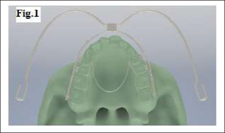
The inanimate objects such as brackets (MBT 0.022″ × 0.028″ slot, Leone American Orthodontics, Italy), S.S molar bands, 0.019″ × 0.025″ S.S wire, transpalatal arch (TPA) (1 mm round S.S wire), IZC-BS (2 mm × 12 mm S.S, AbsoAnchor, Dentos, India), and HPHG (face bow - inner bow = 0.045″, outer bow = 0.072″ S.S, Leone, American Orthodontics, Italy) were developed using reverse engineering technique in “SolidEdge V19,” extracting the dimensional details of the physical parts using precision measuring instruments and fixing these on the 3D model by the projection method. (Fig. 1).
Modified TPA connecting all the maxillary posterior teeth was modeled and adapted 3-5 mm away from the palate to achieve clearance for the intrusion movement and also to had an intra-arch posterior unit rigid connection, thereby minimizing tipping movements for both, HPHG and IZC-BS groups (Fig. 1).
3D Model, Occlusal view
Assemblies and Force Application
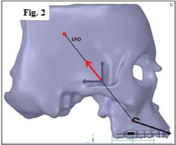
The headgear inner bow was passively adapted 1-2 mm away from the dental arch and attached to the headgear tube of the first molar bands. As the terminal ends of the headgear outer bow (hooks where elastics are attached) were mathematically unnecessary for FEM, they were disregarded. Headgear traction was simulated virtually by applying 450 g/side posterior directed force through the center of resistance (COR) of the posterior maxillary segment, 35° above the palatal plane (above the COR of maxilla) to simulate the clinical HPHG. (COR of posterior maxillary segment was identified by FEM.) (Fig. 2).
HPHG, outer bow showing angle, direction of force and COR of maxillary posterior segment (LFO- Line of Force of Zero moment)
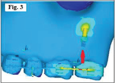
IZC-BS was placed buccal to the mesiobuccal root of the maxillary second molar, 20 24-26 mm above the maxillary occlusal plane and second molar, so as to form an insertion angle ranging from 55° to 70° relative to the maxillary occlusal plane,21, 22 intrusive force of 450 g/side was applied bilaterally to the maxillary posterior dentoalveolar unit from IZC-BS (Fig. 3).
IZC-BS placement and direction of force
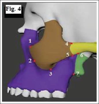
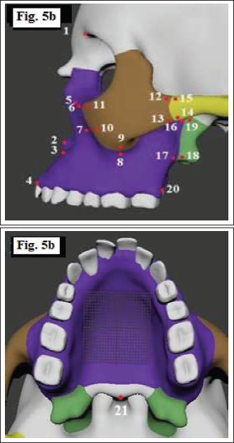
Three sutures were studied and the locations of the suture points along with the surface landmarks in the maxillofacial bone are shown in Figs. 4 and 5.
Suture points: 1, 2 & 3- Zygomaticomaxillary suture- ZMS (superior, middle and inferior); 4, 5- Zygomaticotemporal suture- ZMT (superior and inferior) and 6, 7- Pterygomaxillary suture- PMS (superior and inferior).
The 3D FE model consisted of 10 node solid elements. Three degrees of freedom were allowed for selected nodes of interest and restraints were established at all other nodes of the cranium lying on the symmetrical plane.
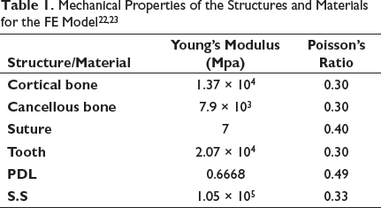
Assigning the Material Properties
Interpretation of Results
The distributions of stresses (MPa) and displacement (mm) were represented as different color bands showing different magnitudes. The red column of the spectrum indicates the maximum level followed by different shades of orange, yellow, green, and blue, while dark blue represents the minimum level.
Results and Discussion
The result of an FE analysis is called post processing. The results were obtained as distribution of stresses and displacement of the maxillofacial surface landmarks, sutures, teeth, PDL, and IZC-BS. On application of 450 g of intrusive force bilaterally on posterior maxillary dentoalveolar segment by HPHG and IZC-BS, the following observations were made;
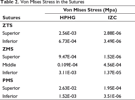
Von Mises Stress Contours of Circum-Maxillary Sutures
Von Mises Stress in the Sutures
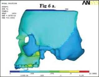
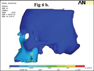
Von Mises Stress Contours of Maxillofacial Structures
The stresses seemed to be generalized radiating to cranium with HPHG group. These were seen more pronounced in the frontomaxillary areas, posterior maxillary infrazygomatic regions especially superior area in front of PMS, second premolar, and first molar region (Fig. 6a). However, in the IZC-BS group, stress distribution was only concentrated at the IZC-BS site and area surrounding the first and the second molars (Fig. 6b). The reason behind this can be that a headgear takes anchorage from cranium and the line of force is bidimensional, whereas the IZC-BS implant site is localized and the force of application is just vertical.
Pattern of stress distribution of the surface landmarks in the maxillofacial structures- HPHG
Pattern of stress distribution of the surface landmarks in the maxillofacial structures- IZC-BS
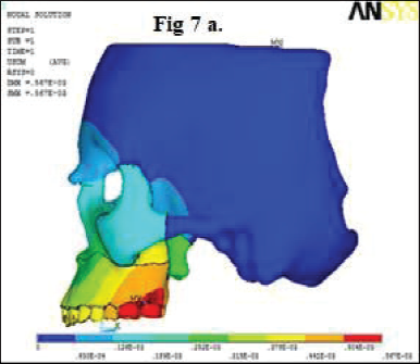
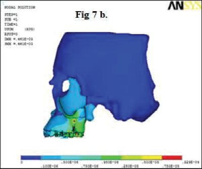
The Maximum Displacement Contours of Maxillofacial Structures
The displacement of surface landmarks in the maxillofacial structures especially maxillary and zygomatic bone region showed more distalization with the HPHG group. Intrusion and expansion were observed in all surface landmarks of maxilla, zygomatic bone, temporal bone, and sphenoid bone with the HPHG group and the expansion was seen for a majority of the surface landmarks with the IZC-BS group (Table 3). Maximum displacement was seen in the first and the second molars in posterior-superior direction which includes maxillary tuberosity. It also showed that the displacement pattern increased from anterio-posterio-superior direction which correlates with the direction of force application, ie, through COR of maxilla using HPHG (Fig. 7a). Maximum displacement was at the IZC-BS site which tends to decrease away in all three planes, which might be because of the direction of force application in the vertical plane only (Fig. 7b). A study done by Gautam et al 27 showed displacements (mm) of various craniofacial structures evaluated along the x, y, and z coordinates with three headgears, and all demonstrated posterior displacement of the maxilla with clockwise rotation of the palatal plane. The distal displacement of the maxilla was the greatest with the straight-pull headgear followed by the cervical-pull headgear. The HPHG had better control in the vertical dimension and mid-palatal suture opening similar to rapid maxillary expansion was observed with all three headgear types suggesting lateral displacements of all the maxillofacial surface landmarks.
Displacement of the surface landmarks in the maxillofacial structures- HPHG
Displacement of the surface landmarks in the maxillofacial structures- IZC-BS
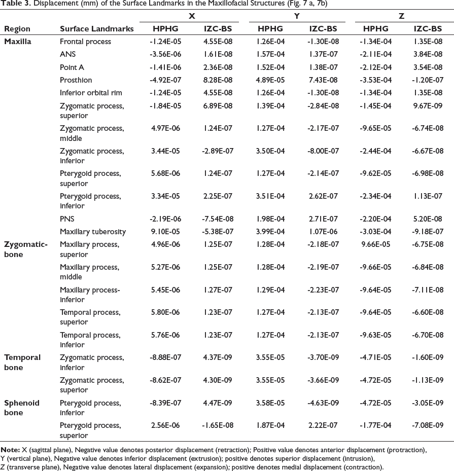
X (sagittal plane), Negative value denotes posterior displacement (retraction); Positive value denotes anterior displacement (protraction),
Y (vertical plane), Negative value denotes inferior displacement (extrusion); positive denotes superior displacement (intrusion),
Z (transverse plane), Negative value denotes lateral displacement (expansion); positive denotes medial displacement (contraction).
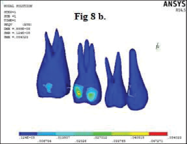
Von Mises Stress Contours of Maxillary Teeth
The HPHG group showed more pronounced stress generation on crowns of maxillary posterior teeth and the maximum stress contours were seen on mid-buccal surface of maxillary first molar for both the groups which can be attributed to the area of attachment of the inner bow and site of traction application for HPHG and IZC-BS, respectively (Fig. 8a and 8b). Since Von Mises stresses were not present at the apical root areas of the maxillary posterior teeth for both the groups, root morphology was assumed to be unaltered and thus they were not considered to be prone for root resorption.
Stress distribution contours of teeth- HPHG
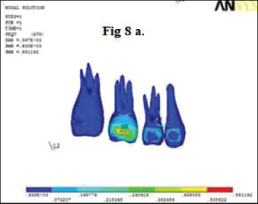
Stress distribution contours of teeth- IZC-BS
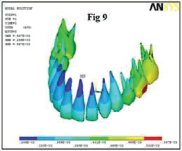
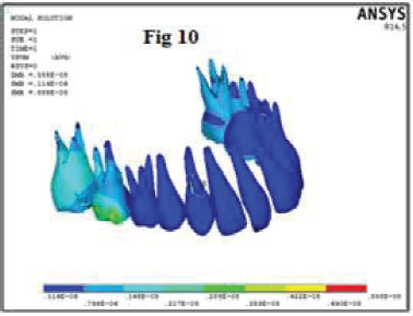
The Maximum Displacement Contours of Maxillary Teeth
The maximum displacement in posterior direction was observed in cusp tip and root apices of the first premolar region and almost equal in second premolar, first molar, and second molar for the HPHG group. The IZC-BS group showed slight posterior displacement in the first molar region. There was more intrusion and expansion with HPHG. This might be because of the fact that the point of force application was more buccal to COR of maxilla with HPHG than IZC-BS. The FEM model revealed that there was almost equal displacement for cusp tips and root apices in all three planes which was in correlation with the findings [Tables 4 and 5, Figs. 9 and 10] and proved that the whole maxillary posterior segment was intruded bodily for both the groups. A study done by Cifter and Sarac 28 concluded that segmental posterior intrusion mechanics with force applications from counterbalancing sides (anterio-posterior, vestibular-palatine) lead to more uniform stress distribution and balanced intrusion than the mechanics with a TPA. Pekhale et al 29 in their study on posterior maxillary segment intrusion using mini-implants and TPA demonstrated that a significant amount of true intrusion of maxillary molars could be obtained with lesser concentration of stresses in the apical area.
Displacement of the all maxillary teeth- HPHG
Displacement of the all maxillary teeth- IZC-BS
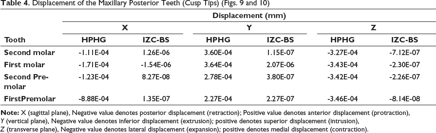
X (sagittal plane), Negative value denotes posterior displacement (retraction); Positive value denotes anterior displacement (protraction),
Y (vertical plane), Negative value denotes inferior displacement (extrusion); positive denotes superior displacement (intrusion),
Z (transverse plane), Negative value denotes lateral displacement (expansion); positive denotes medial displacement (contraction).
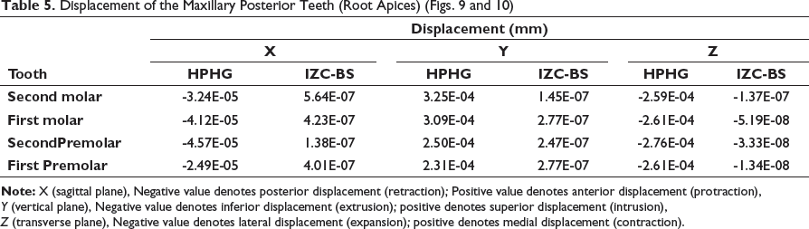
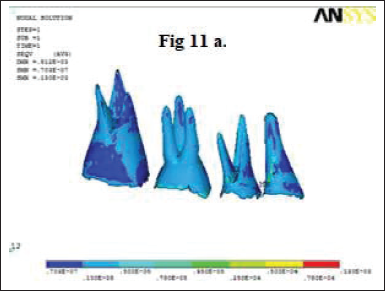
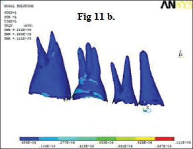
Von Mises Stress Contours of Periodontal Ligament
Although stresses in PDL on all the maxillary posterior teeth were lower in both the groups, but on comparing they were seen more with the HPHG group. It showed that HPHG had more generalized effect on stress distribution than IZC-BS (Fig. 11a and 11b).
Pattern of stress distribution of periodontal ligament- HPHG
Pattern of stress distribution of periodontal ligament- IZC-BS
The Maximum Displacement Contours of Periodontal Ligament
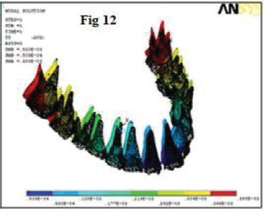
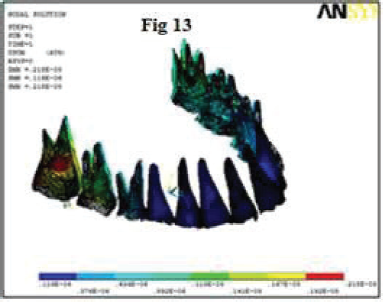
It was observed that displacement contours of PDL on all the teeth were seen more with HPHG than IZC-BS group and also there was no displacement seen in the anterior region for the IZC-BS group. The displacement of PDL was observed highest at the distobuccal roots of the first and the second molars in decreasing order for the HPHG group and furcation areas of buccal roots of the second molar for the IZC-BS group (Figs. 12 and 13); the reason for this might be attributed to the area of implant insertion and traction application site.
Displacement of the periodontal ligament of maxillary teeth- HPHG
Displacement of the periodontal ligament of maxillary teeth- IZC-BS
The Maximum Displacement Contours and Von Mises Stress Contours of IZC-BS
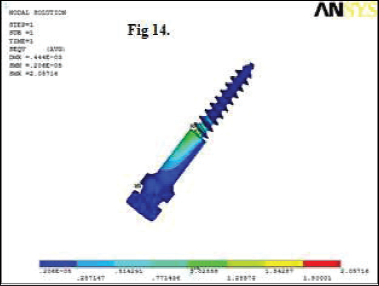
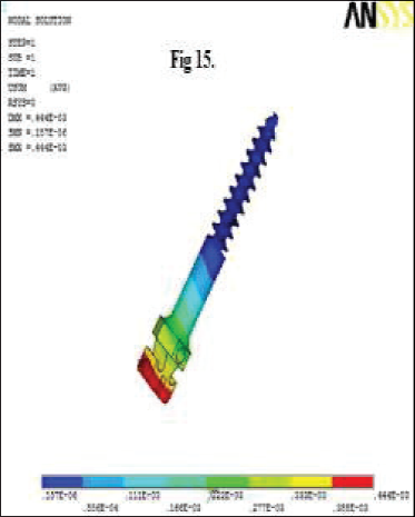
Increased displacement was seen from neck-thread junction to head areas of IZC- BS (Fig. 14); the maximum stress was present in the head of IZC-BS (Fig. 15). This might be because of more load concentration at the site of attachment.
Von Mises stress contours on IZC
Displacement contours on IZC
Limitations of any study using static FE analysis is that it only simulates the initial tooth movement and stress distributions. It is impossible to derive what precisely happens over certain length of time when the same loading conditions continue. During the treatment cycle, the ongoing movements and stresses can differ because of the changes in force systems and biologic responses. 28 The constant values used for the physical properties of the tissues, which would normally alter clinically through the histological process, and the assumption that PDL is homogeneous, isotropic, and uniform in thickness can cause differences between clinical applications and simulation studies. Also, because of individual variations, it is impossible to simulate an exact mathematic model to validate each case. However, similarities between the results of this study and clinical studies with parallel mechanics show that the FE models generated are accurate enough to simulate clinical conditions.30-32
Conclusion
In this study, the FE model and data were correlated and analyzed for 2 intrusive mechanics using HPHG and IZC-BS for stress distribution and displacement patterns on craniofacial structures, and the following were the conclusions made: Overall, stresses on the maxillofacial sutures (ZMS, ZTS, and PTM) and surface landmarks on the maxillary, zygomatic, temporal, and sphenoid bone were generalized and more pronounced for the HPHG group. Moderate stresses were found to be present around the neck-thread junction of IZC- BS and the highest displacement was found to be present around the head of IZC-BS. Intrusion and expansion of the maxillary posterior segment were more pronounced with HPHG. The displacements tend to increase from anterior to posterior region for the HPHG group, whereas for the IZC-BS group, the displacement was more localized around the implant region and the second molar area. Von Mises stresses were not present at the apical root areas of the maxillary posterior teeth for both the groups. Hence, root morphology was assumed to be unaltered.
Hence, it can be said that on applying equal amount of intrusive force bilaterally for both the groups, stress patterns and teeth displacement of maxillary posterior segment were more pronounced and effective for HPHG; however, root morphology was assumed to be unaltered because of the absence of Von Mises stresses at the apical root areas of the maxillary posterior teeth for both the groups.
Footnotes
Statement of Informed Consent and Ethical Approval
Necessary ethical clearances and informed consent was received and obtained respectively before initiating the study from all participants.
Declaration of Conflicting Interests
Funding
The authors received no financial support for the research, authorship, and/or publication of this article.