
Abstract
Objective:
The study was conducted to evaluate stress pattern and deformation in mid-palatal suture and posterior dentoalveolar area during maxillary expansion therapy with two different types of rapid maxillary expansion by finite element method study.
Methods and Methodology:
The finite element analysis was performed on a model of maxilla, with narrow maxillary base and teeth digitally reconstructed, based on CBCT images, acquired by child (age 12.5 years) but not in permanent dentition stage from available pool data.
Result:
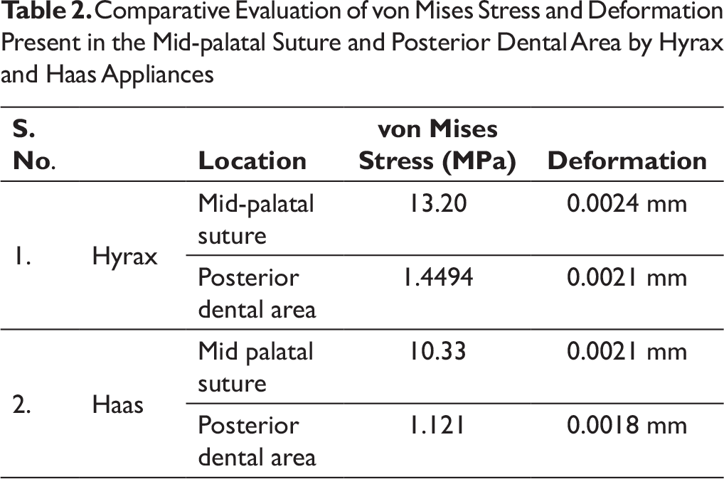
More amount of stress was observed in mid-palatal suture and posterior dental alveolar area by using the Hyrax appliance as compared to the Haas appliance. Stress pattern evaluated in mid-palatal suture depicts maximum stress concentration on the anterior region of mid-palatal suture at the position of incisive papilla. Deformation in maximum quantity is observed in central incisors. Maximum stress generation and deformation are observed in lingual region of premolar and molar areas. Minimum stress generation and deformation are observed in the posterior part of last molars.
Conclusion:
Hyrax produces more stress and deformation in mid-palatal suture as well as in the posterior alveolar segment in comparison to Haas appliance. Better results in the immediate skeletal response were obtained by the Hyrax-type expander as compared to the Haas type.
Abbreviations
FEM: finite element method
RME: rapid maxillary expansion
Introduction
In dentistry, if a constricted maxillary arch is diagnosed in an adolescent patient, the preferred treatment plan would be orthopedic expansion. Expansion appliances are commonly used to correct the constriction present, involving separation of the mid-palatal suture. Rapid maxillary expansion (RME) is usually performed to widen the maxilla in order to correct the posterior crossbite, to gain space, and to resolve maxillary dental crowding.1-4 Rapid maxillary expansion treatment most probably exerts forces of 15 to 50 N on the maxillary suture and para-maxillary structures, which prompt changes in other skeletal structures adjacent to the maxilla as well. 5 For proper diagnosis and assessment of the mid-palatal suture prior to RME, occlusal radiographs have been introduced by Revelo and Fishman. 6 With increased skeletal growth and development, progressive ossification in the circum-maxillary sutures occurs along with increased thickness of the bony structures, decrease in their versatility, and expanded interdigitation of the mid-palatal suture. Each of these variables add to opposition in opening of the mid-palatal suture and stable expansion of the maxilla. Various studies have been conducted to assess widening of the nasal cavity, reformation of the maxillary sinus, and changes in circum-maxillary sutures and even the sphenoid bone of the cranial base possible after RME treatment.
The finite element method (FEM) was developed in 1943 by Richard Courant, 7 which concentrates on statically uncertain frameworks with relative precision. The finite element analysis (FEA) is a computer simulation technique used in orthodontics to analyze stress distribution in biologic systems such as periodontal ligament and alveolar bone, as well as to find the center of resistance of a tooth or group of teeth. Because of its consistency, precision, and cost adequacy with no unsafe experimentation, this technique will be utilized in the present study. Rapid palatal expansion (RPE) has been used as an effective treatment for growing patients since its first introduction by Angell 8 in 1860. Graber and Swain 9 also upheld RME for the treatment of cleft lip and palate. From that point of time, clinicians have progressively included RME in the treatment of their patients.
Rapid palatal expansion is mostly indicated in patients having lateral discrepancies involving unilateral or bilateral posterior crossbite or patients having severely constricted arch.10, 11 Bell 12 stated in his studies that positive skeletal treatment by RME results in correction of posterior teeth discrepancy and asymmetric condylar position.
The thought process of this investigation is to evaluate the stress magnitudes and directions along the mid-palatal suture and to compare stresses generated in transverse axis by two different kinds of RME appliances. Results of this study will be helpful in predicting the prognosis of RME and will also help orthodontists to clinically select one among two of the commonly used RME appliances, namely Hyrax or Haas appliance.
Materials and Methods
To pursue the motive of this study, it was required to generate quality 3D mesh. This necessitated the utilization of finite element software with good generation and meshing facility for accurate stress analysis. Hence, it was decided to use SolidWorks 2016 (Dassault Systèmes SolidWorks Corporation, Waltham, MA), Pro Engineering (PTC) and ANSYS 16.0 (Ansys, Inc., Canonsburg, PA) for the study.
The FEA was performed on a model of maxilla, with narrow maxillary base, and teeth digitally reconstructed based on CBCT images acquired by the patient. These images were developed from the pool data of CBCT of a child (age 12.5 years) but not in permanent dentition stage. Modeling of the maxillary body was carried out, which included mid-palatal suture, teeth, cortical and cancellous bone along with RME appliances, that is, Hyrax and Haas on maxillary body. In terms of bone, two different types—cancellous and cortical bones—were considered. The alveolar crest edge was thought to be 1.08 mm occlusal to the cementoenamel junction (CEJ) of the tooth and its property were appointed.13-16
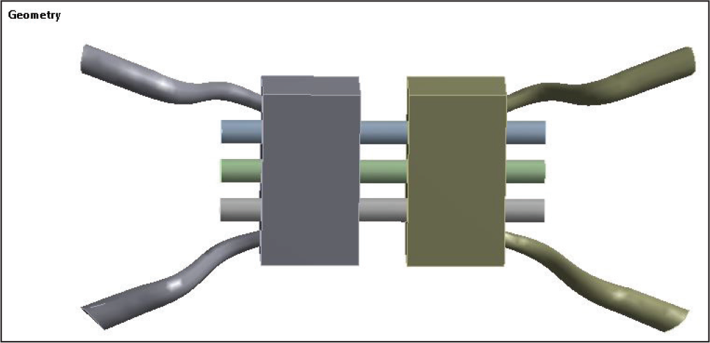
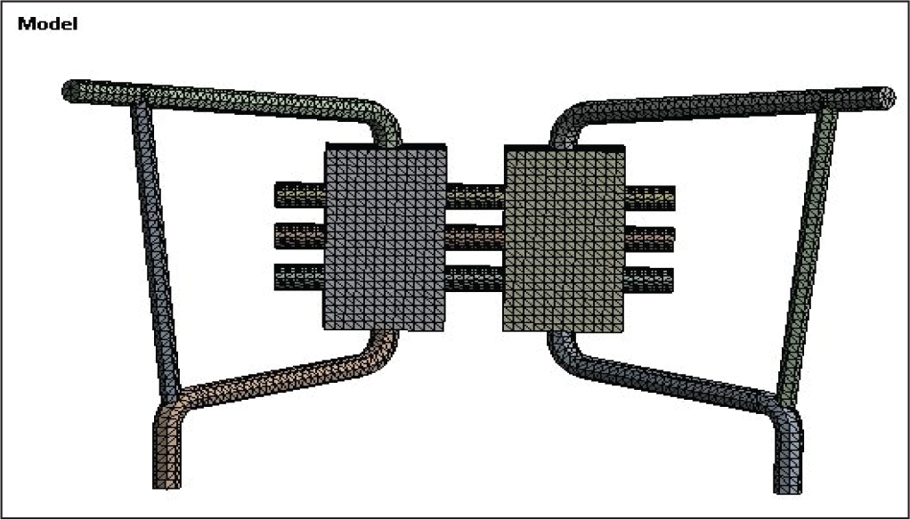
Mid-palatal suture properties were allocated to the gap junction between two palatal shelves. The geometry of the maxilla and teeth were digitally reconstructed. Solid model of teeth was constructed. A 3D model of conventional Hyrax expansion screw (Leone, Italy) was laser scanned using a white light 3D scanner (Figures 1 and 2). This expansion screw was activated to perform 0.25 mm widening per turn, and twice-a-day activation protocol was pursued. Then, a custom-fabricated Haas model was constructed, which was laser scanned like the previous model to create a 3D image.
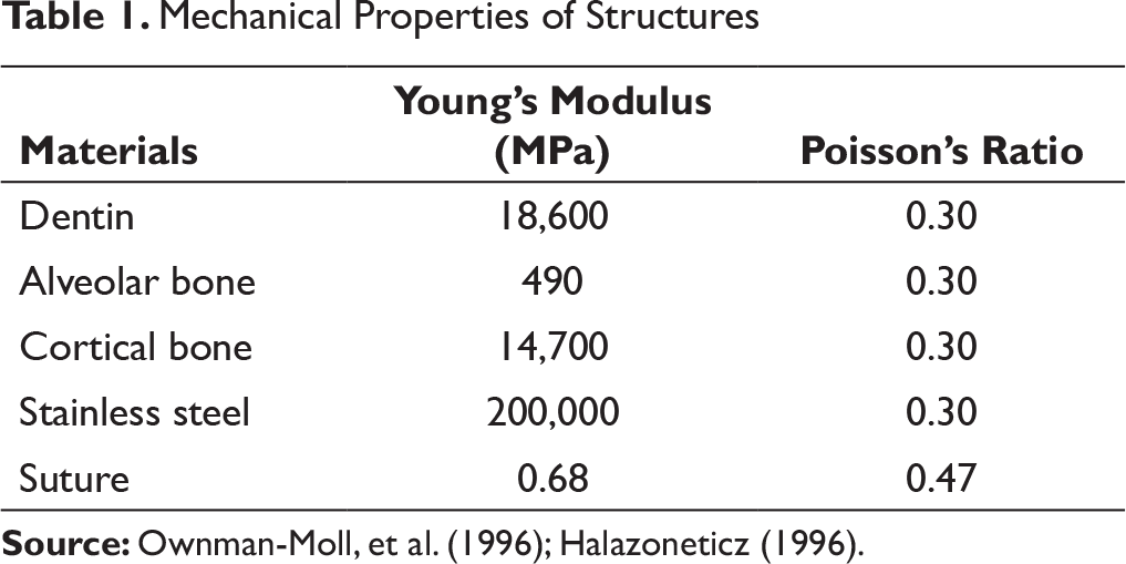
The material properties of the elements, which closely resembled tooth structures, alveolar bone, sutures, and stainless steel, were assumed to be isotropic, homogeneous, and linearly elastic. Specific Young’s modulus and Poisson’s ratios were assigned to different structures as given and assessed by past investigations (Table 1).13-18
Model of Hyrax Appliance
Model of Haas Appliance
Mechanical Properties of Structures
Boundary and Loading Conditions in Maxillary Model
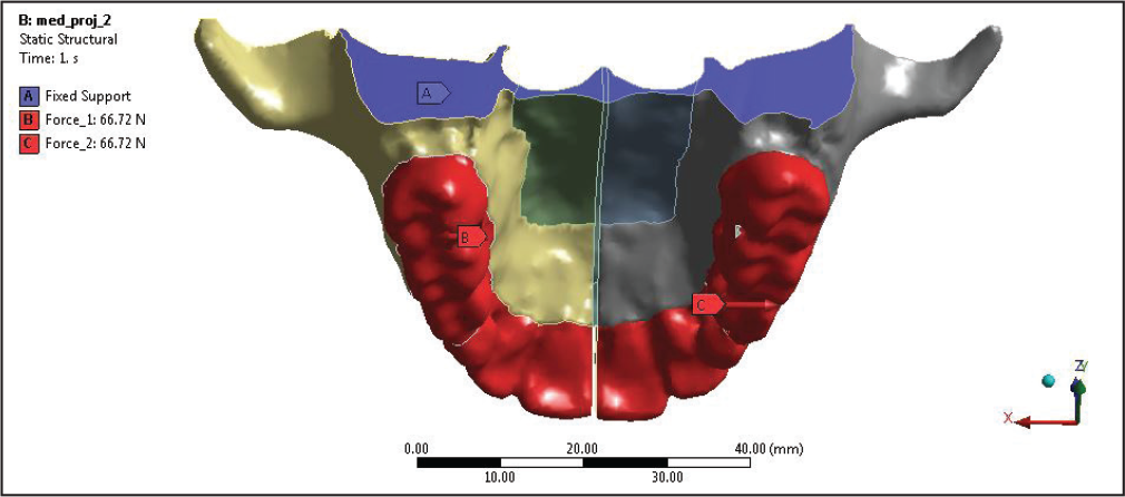
The validation of the model was processed. After proper validation, loading, and boundary conditions (Figure 3) were assigned to the model. Boundary conditions were defined at all peripheral nodes of the bone with zero degree of movement in all directions so as to ascertain stress pattern and deformation in mid-palatal suture and posterior dentoalveolar area. 19
After all these conditions were checked, a tensile reciprocal force of 15 pounds was applied along the X-axis of the last three posterior teeth where Hyrax and Haas appliances were attached. This computerized model was transferred to ANSYS software (ANSYS WB 18.1). Stress distribution in the mid-palatal suture was analyzed using ANSYS (version 12.1, ANSYSn Inc., Canonsburg, PA).
The numerical data in FEM produces colorful maps of Von Mises stress and various principal stresses, named maximum principal stress (MaxPS), middle principal stress (MidPS), and minimum principal stress (MinPS), which were calculated for whole study. Stress pattern and deformation value were measured along the mid-palatal suture and posterior dentoalveolar area.
Results
Stress and Deformation Results From Hyrax Appliance
Initial analysis was carried out by placing Hyrax appliance for applying transverse force. The boundary conditions and force applied remained same for all the models.
Stress Pattern and Deformation on Mid-palatal Suture by Hyrax Appliance
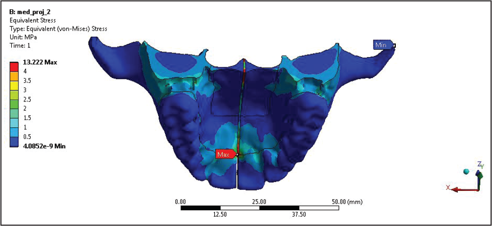
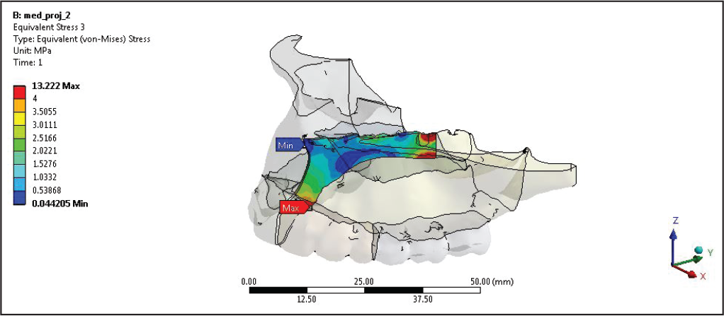
According to the stress pattern observed in mid-palatal suture, maximum stress has been observed in posterior most part of the mid-palatal suture (Figures 4 and 5), and also the stress concentration was found higher on the anterior region of mid-palatal suture at the position of incisive papilla (13.20 MPa). So, overall maximum stress was concentrated on the location of incisive papilla below the junction of two central incisors and on the posterior most part of maxilla.
Deformation in maximum quantity is observed in central incisors (0.0024 mm) (Figures 6 and 7), which degrades as we move posteriorly. Maximum deflection can be seen in central incisors, as they move apart during maxillary expansion.
Stress Pattern and Deformation in Posterior Dentoalveolar Area
According to the result obtained while applying the transverse force along the mid-palatal suture, posterior teeth also experienced the force and stress. Maximum stress generation (1.4494 MPa) (Figure 8) and deformation (0.0021 mm) (Figure 9) were observed in the lingual region of premolar and molar areas. Minimum stress generation and deformation were observed in the posterior part of last molars.
von Mises Stress on Mid-palatal Suture After Applying HYRAX appliance
von Mises Stress Only Shown at Mid-palatal Suture After Applying HYRAX appliance
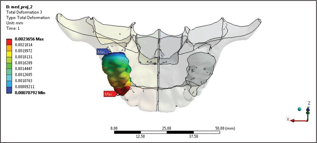
Deformation Pattern Calculated at Mid-palatal Suture After Applying Hyrax Appliance
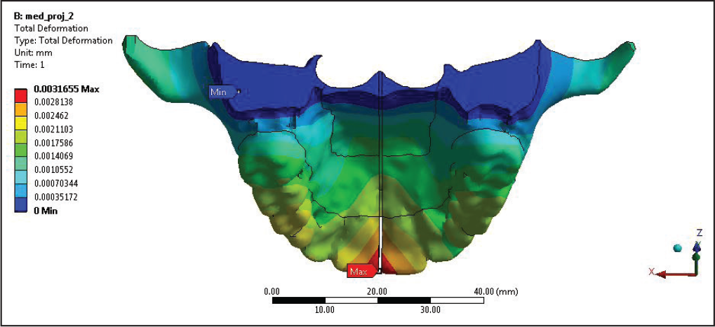
Deformation Pattern Calculated at Mid-palatal Suture After Applying Hyrax Appliance
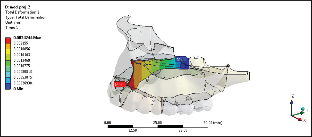
Deformation Pattern Calculated on Right Posterior by Applying Hyrax Appliance
von Mises Stress on Mid-palatal Suture After Applying Haas Appliance
Stress and Deformation Results From Haas Appliance
Stress Pattern and Deformation on Mid-palatal Suture by Haas Appliance
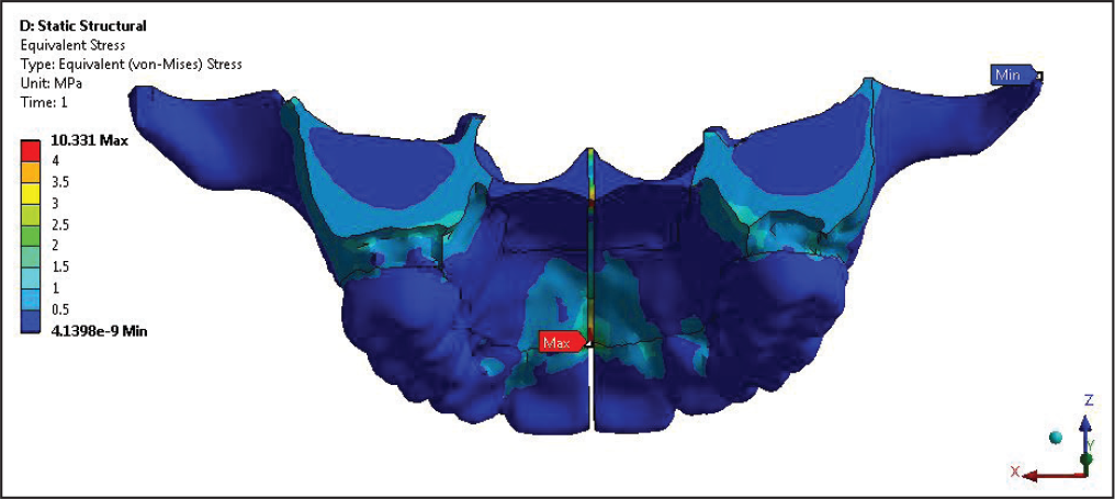
According to stress pattern observed in the mid-palatal suture, maximum stress has been observed in the anterior region of mid-palatal suture at the position of incisive papilla (10.33 MPa) (Figures 10 and 11), and also the stress concentration was found to be higher on the posterior most part of mid-palatal suture. So, overall maximum stress was concentrated on the location of incisive papilla below the junction of two central incisors and on the posterior most part of maxilla.
Deformation in maximum quantity was observed in central incisors (0.0821 mm) (Figure 12), which degrades as we move posteriorly. Maximum deflection can be seen in central incisors as they move apart during the maxillary expansion.
von Mises Stress Only Shown at Mid-palatal Suture by Haas Appliance
Deformation Pattern Calculated at Mid-palatal Suture by Haas Appliance
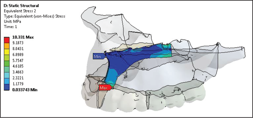
von Mises Stress Calculated on Posterior Tooth After Applying Haas Appliance for Maxillary Expansion
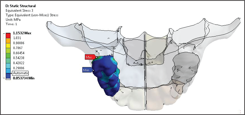
Stress Pattern and Deformation on Posterior Dentoalveolar Area
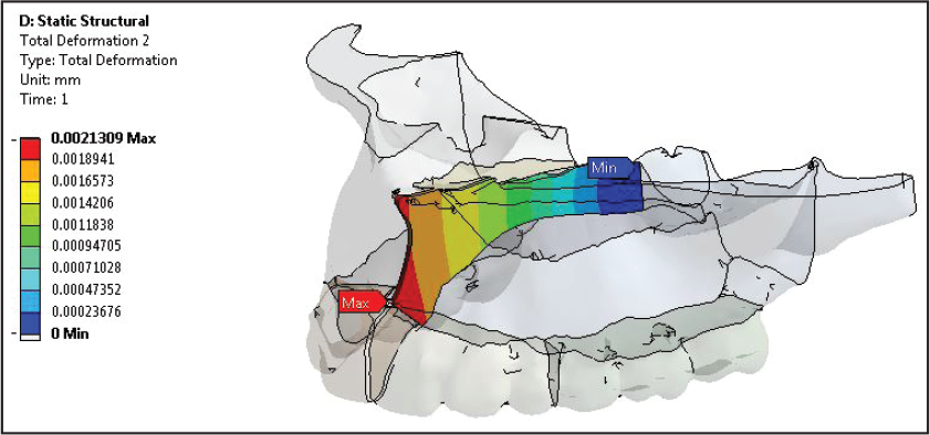
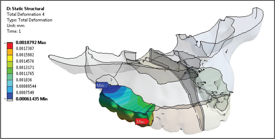
According to the results obtained, while applying the transverse force along the mid-palatal suture, posterior teeth also experienced the force with the generation of stress. Maximum stress generation (1.121 MPa) and deformation (0.018 mm) were observed in the palatal region of premolar and molar areas (Figure 13; Tables 2 and 3).
Deformation Pattern Calculated on Right Posterior Tooth After Applying Haas Appliance
Comparative Evaluation of von Mises Stress and Deformation Present in the Mid-palatal Suture and Posterior Dental Area by Hyrax and Haas Appliances
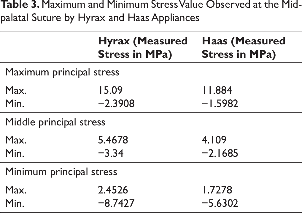
Maximum and Minimum Stress Value Observed at the Mid-palatal Suture by Hyrax and Haas Appliances
Discussion
During the course of this study, a maxillary model consisting of mid-palatal suture, teeth, palate, and alveolar bone was designed using CBCT model of a 12.5-year-old child. Separately, Hyrax and Haas maxillary expansion appliances were designed. With the help of this FEA study, we evaluated the magnitude of stress and deformation and their pattern followed by comparing Hyrax and Haas.
According to Isacson et al, 20 with a single turn of jackscrew produces 3 to 10 pounds of force which will generate 20 pounds of force after multiplying all turn of a day. Separation of central incisors occur between the 9th and 12th turns in all the patients.
In our study, a force of 15 pounds 2 was applied on the palatal surface of premolar and molar areas in transverse direction, applying the same boundary conditions on the maxillary model for both the appliances, that is, Hyrax and Haas. Loading conditions were changed accordingly as each appliance clinically produces different load-activation characteristics as per their designs.
The major difference between two types of appliances is the presence of band attachment in the Hyrax appliance and acrylic pad in the Haas appliance. If we do consider the theory given by Haas, 21 better utilization of acrylic pad is to increase the anchorage for better skeletal response during RME.
There are three types of stress simulated in this study: (a) maximum principal stress (MaxPS), (b) minimum principal stress (MinPS) and (c) Von Mises stress. All these values of stress depict different properties and nature of stress. Von Mises stress is the most stable stress; it shows the equivalent stress that is used to determine whether a given material will yield or fracture, which is mostly used for ductile materials. 22
MaxPS shows the area undergoing the highest tension, which is responsible for bone apposition, while MinPS shows the area undergoing the highest compression responsible for bone resorption, thus play important role in bone remodeling. 23
In the present study, maximum stress pattern has been observed in the mid-palatal suture in the posterior most part of mid palatal suture (Figure 9), and also the stress concentration was found to be higher on the anterior region of mid-palatal suture at the position of incisive papilla. So, overall maximum stress was concentrated on the location of incisive papilla below the junction of two central incisors and on the posterior most part of maxilla. Deformation in maximum quantity is observed in central incisors (Figure 10), which degrades downward as we move posteriorly. Maximum deflection can be seen in central incisors, as they move apart during the maxillary expansion.
According to results obtained from this research, the Hyrax appliance produces more stress and deformation in the mid-palatal suture as well as in the posterior alveolar segment (where the force is directly applied, ie, premolars and molars) as compared to the Haas appliance. However, various studies have been conducted by different authors between RME appliances by computerized cast analysis, 19 laser scanning technique, and computed tomography. 20 All these studies confirm that the Haas appliance demonstrated greater orthopedic movement, and the Hyrax appliance demonstrated greater dentoalveolar expansion. Also, a study conducted on RME appliances using 3D FEM supports the theory that larger sutural displacement occurs with the Haas appliance.
In contrast to all the above-mentioned studies, the results of our research can be clarified by different appliance design: all the major differences appear because of difference in anchorage supporting system, that is, connection of jackscrew with molar teeth. In the Hyrax-type appliance, the jackscrew is directly associated with the band of a rigid stainless steel wire, not at all like the Haas-type appliance, where the acrylic pad is in charge of interfacing the stainless steel structure to the jackscrew. As per a past report about the biomechanics of RME, appliances which utilize an acrylic interface with the teeth are far less hardened than those developed exclusively of stainless steel wire. 17 However, the acrylic cushion would be significant, particularly during retention period, when it would prevent the bone from moving the teeth, thus preventing orthopedic relapse of maxillary expansion.
As this study was not carried out for long-term use and retention periods, we have only evaluated and assessed the immediate effect of RME appliances. So, for better understanding of long-term effect of both appliances, that is, Hyrax and Haas, specially during retention and post-retention period, further research is required. In the same way as other FEM research studies, this investigation also had restrictions because of the scientific model, as premises and presumptions were used to create the FEM from a solitary patient, which may not be totally similar to all the inclusive community with individual variability just as different clinical circumstances.
It may be possible, that long term result of RME expansion appliance did not support this investigation as it is based on quick impacts of expansion. Thus, we can conclude, that if we do not consider long-term treatment duration and basically focus on treatment responses within few months, Hyrax provides better results than Haas. FEM elements in our model representing biological tissues were considered isotropic and solved with linear-elastic properties. Because only one palatal suture was included in the FEM model and the rest of the sutures were not considered, the results were obtained only in transverse axis and not in sagittal or vertical direction.
The results of the present investigation, however, offer probably right clinical potential outcomes, which must be kept in acknowledgment with guarded positive thinking. Hence, further research is expected to think about the impact of rapid maxillary expansion appliance on mid-palatal suture and dentoalveolar area.
Conclusion
From the results of our study, we concluded that:
The stress pattern evaluated in the mid-palatal suture that depicts maximum stress was found to be higher on the anterior region of mid-palatal suture at the position of incisive papilla. Also the same stress value was observed in the posterior most part of the maxilla. So, overall maximum stress was concentrated on the location of incisive papilla below the junction of two central incisors and on the posterior most part of maxilla. Deformation in maximum quantity was observed in the central incisors, which degrades downward as we move posteriorly. Maximum deflection was seen in the central incisors as they move apart during maxillary expansion. According to the results obtained while applying the transverse force along the mid-palatal suture, some amount of stress is also generated in the posterior teeth. Maximum stress generation and deformation were observed in the palatal region of premolar and molar areas. Minimum stress generation and deformation were observed in the distal part of last molars. According to this study, whenever load is applied on premolars and molars from the palatal side, the Hyrax appliance produces more stress and deformation in the mid-palatal suture as well as in the posterior alveolar segment in comparison to Haas appliance. Better results in the immediate skeletal response were obtained by the Hyrax-type expander as compared to the Haas type.
Footnotes
Acknowledgments
I would like to thank Dr Ashish Garg and Dr Rakesh Thukral for guiding me in the course of completing this article. I am immensely thankful to Dr Bhavna Virang, Ex-Reader, Department of Orthodontics and Dentofacial Orthopedics, who has helped in making this article complete. I am obliged to her for being a constant source of helpful guidance to me throughout this period of dissertation. I am at loss for words in thanking Dr Geet Chaddha and Dr Shobhit Bajaj as their constant encouragement and guidance have been my strength and helped me throughout the course of this article. Process of FEM was not possible without the help I received from my FEM engineers Mr Manoj Bangre, Mr Tushar Dongre, and Mr Deepak Shinde.
Availability of Data and Material
All data generated or analyzed during this study are included in this published article (and its supplementary information files).
Statement of Informed Consent and Ethical Approval
Necessary ethical clearances obtained from institution,RC/2018/PG/08 ; informed consent not applicable due to in-vitro nature of study
Declaration of Conflicting Interests
Funding
The authors received no financial support for the research, authorship, and/or publication of this article.