
Abstract
Miniscrew-assisted rapid palatal expansion (MARPE) has added a new dimension to the world of orthodontics with its use in skeletal expansion of transverse problems in adult population. However, there are few limitations noted with the use of prefabricated MARPE designs such as adaptation to the palate or minscrew fit in cases of high arched palate, which compromises with the anchorage and final outcome. The aim of this article is to use digital workflow to 3d print a MARPE with the aid of cone beam computed tomography, which would overcome the deficiencies of a prefabricated MARPE design and would provide greater rigidity and anchorage value, and predictable skeletal expansion.
Keywords
Introduction
Rapid maxillary expansion (RME) devices have been routinely used in the correction of transverse discrepancies such as unilateral, bilateral crossbite in young individuals. 1
However, managing problems in the transverse dimension in adults has always been a challenge. To overcome this, miniscrew-assisted rapid palatal expansion (MARPE) device was introduced. 2
Ever since, studies have shown the effectiveness of the MARPE in adults with transverse discrepancy.3 –4 It helps to overcome skeletal resistance to RME, protects anchor teeth, and reduces buccal tipping of the posterior teeth. 1
Currently, a lot of dilemma exists in the world of orthodontics as to what is the ideal design of a MARPE, ways and means to achieve the ideal skeletal outcome, whether the leap ahead is with customized MARPE, or still the prefabricated ones are good enough in all clinical scenarios.
In today’s digital era, 3D technology has found a plethora of applications in orthodontics such as digitizing casts, for individual bracket base manufacturing, aligners, and robotic wire bending, 5 yet traditional appliances such as hyrax, lingual, and transpalatal arches are routinely fabricated with conventional laboratory technique.
3D printing in combination with computer-aided manufacturing (CAD-CAM) can be used to fabricate even traditional orthodontic appliances and bring about greater precision in their outcome.5
From “prefabricated” to “personalized,” the objective of this article is to illustrate the method employed to 3D print a CAD-CAM designed MARPE using cone beam computed tomography (CBCT) support—a “Made in India” appliance.
Why the Need for Customization of Marpe
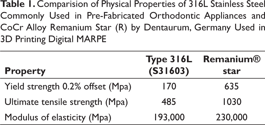
The regular MARPE and the MSE has been effective in bringing about skeletal expansion in adults, yet they have serious limitation in cases of narrow and high arched palates. The standard expansion screw sometimes does not fit into the palatal depth and therefore due to faulty screw insertion, the anchorage becomes seriously compromised (Figure 1). Customization5 –6 of MARPE would bring about—almost in every case—better fit and adaptation, choice of options in design, two screws or fours screw options, and better rigidity (Cr-Co Alloy Remanium Star, Dentaurum) (Table 1) to the system which would invariably bring better and more predictable skeletal expansion. The advantages of the customized design clearly contemplate that the future lies in these form of appliances.5 –6
Digital Workflow for Construction of Customized 3D Digital MARPE
Step 1: Intraoral scanning6 is done for the upper and lower arch using TRIOS 3 scanner from 3 shape. The stereolithography (STL) files of the scan are then imported to designing software of choice. Many open source software (Mesh Mixer, Blender for dental, etc) are available and can be used based on the choice of the operator (Figure 2).
Comparision of Physical Properties of 316L Stainless Steel Commonly Used in Pre-Fabricated Orthodontic Appliances and CoCr Alloy Remanium Star (R) by Dentaurum, Germany Used in 3D Printing Digital MARPE
Adaptation Issues in a Noncustomized MARPE

Step 2: The scan is then cleaned and digital base is made followed by a Digital Kesling setup for segmenting individual teeth (Figure 3).
Step 3: CBCT is done for maxilla and the files are converted to STL for better superimposition (Figure 4).
Step 4: These files are then superimposed with the intra-oral scans to be used as reference while planning of temporary anchorage device (TAD) placements, which avoids any chance of root contact (Figure 5).
Step 5: Expansion hyrax (FORESTADENT) scans is digitally placed in the palate (Figure 6). The palatal rests on the first molars are kept 0.75 mm thick and have a gap of 0.05 mm with the teeth for the purpose of cementation. The connector arms connecting the hyrax and the palatal rests on first molars are 1.5 mm in diameter and cylindrical in shape. The two circular attachments (metal rings) for insertion of the TADs are 1.5 mm in thickness and the inner circumference is 2.2-2.5 mm which enables easy insertion of a TAD of 2 mm in diameter. These are closely adapted to the palatal contour to aid in proper placement of the TADs. The orientation of the insertion holes are made in such a way that two TADs are oriented parallel to each other and are located on either side of the midpalatal suture (Figure 7). Here, TADs (Medusa headless TADS from FavAnchor, Favourite Supplies, India) of 2 × 12 mm were scanned and digitally placed in the safe T-zone (Figure 8) of the palate. 7
Intra-oral Scans and STL Files (Pre)

Digital Models from STL Scanned Files (Pre)

CBCT of the Maxilla (Pre)

Superimposition of CBCT over Digital Models for Assessment of TADs Placement

Digitally Placed MARPE on Superimposed CBCT and Digital Models

Digital Assessment of TAD Position and Angulation

Safe Zone (T-Zone) for Position of Palatal TADs

3D Printed MARPE Assembly Laser Welded on the Hyrax

Step 6: The final digital models are then checked for adequate clearance from the roots of the anterior teeth and distance/adaptation to the palate. They are then exported in STL format (without the digital data of TADs) for direct metal laser sintering in M100 EOS GmbH System. Once the appliance is metal-printed, it is electropolished and hyrax is laser-welded in position (Figure 9)
Step 7: The appliance is then cemented using Relyx U200 from 3M Unitek following the bonding protocol as advised by the manufacturer. Once the cementation is done, TADS are placed and expansion can be started as per patient requirement (Figure 10).
Expansion protocol of two ½ turns per day (total 0.8 mm expansion per day) at a difference of 10-12 hours a day was followed for the next 10-12 days. Skeletal expansion with considerable opening of the midpalatal suture was noted (Figures 11 and 12). Superimposition of digital models and CBCT (Figure 13) suggested minimum dental expansion but primarily skeletal expansion achieved.
Intra-oral Scans after Maxillary Expansion (Post)

Occlusal Radiograph: Pre and Post Expansion Comparison

CBCT of the Maxilla (Post)

Superimposition of CBCT Over Digital Models post Expansion

Conclusion
CAD-CAM designed MARPE with increased accuracy is therefore a feasibility in today’s digital era. Clinically it has shown that it is an efficient skeletal expansion device with better adaptation to underlying anatomical structures (palate). The future lies in the acceptance of advanced technology in optimizing clinical outcome. However, a learning curve must be expected as digital printing of conventional orthodontic appliances is at its infancy and the cost–benefit ratio also needs to be equated primarily on grounds of case selection.
Footnotes
Declaration of Conflicting Interests
The authors declared no potential conflicts of interest with respect to the research, authorship, and/or publication of this article.
Funding
The authors received no financial support for the research, authorship, and/or publication of this article.