
Abstract
Abstract
Introduction: Correction of deep bite is one of the major challenges of orthodontic treatment. Mini-implants provide stable intra-oral anchorage and facilitate the maxillary incisors to be intruded without the usual side. The purpose of this finite element study was to evaluate the stress distribution around the mini-implant during maxillary anterior intrusion under different conditions of different angulations and different positions of implant.
Material and Methods: Finite element analysis was carried out. Stress under the following 4 conditions was analyzed: (a) single central implant placed at 90°, (b) single central implant placed at 120°, (c) bilaterally placed implant at 90°, and (d) bilaterally placed implant at 120°.
Results: The displacement seen with 90° angulation in the single implant case is less compared with the 120° angulation case for all the 6 maxillary anterior teeth. Also, in the bilateral implant case, the Von Mises stress is less when the 90° angulation case is compared to 120° angulation case. But in bilaterally placed implant, the stress gets distributed evenly in the anterior region. The stress in 90° angulation cases seems to be concentrated at the center.
Conclusion: Stresses measured on the teeth are less and distributed more evenly when the point of force application is bilateral. It was also observed that the stress increases with increase in the angulation of the implant. As the contact between the implant and the bone increases, the stability increases. Hence, the implant should be obliquely inserted into the bone. Concentrated stresses are not favorable as they can increase the risk of bone and root resorption.
Introduction
Orthodontics is gradually changing from a judgment-based practice to an evidence-based practice. Correction of deep bite is one of the major challenges of orthodontics treatment. Many studies and researches were performed to compare different methods of deep bite corrections.1, 2 In most instances, the deep bite is corrected by anterior intrusion, extrusion of posterior teeth, or a combination of anterior intrusion along with posterior extrusion. But posterior extrusion is undesirable in vertical growers.3, 4 Orthodontic tooth movements have always been restricted to action–reaction reciprocal force mechanics for anchorage control. 5
On analyzing the lateral cephalograms of patients, if the lower lip covers more than 4 mm of the maxillary central incisors crown, then it is a result of over-eruption of the maxillary incisors. 6 Intrusion by Burstone’s 3-piece intrusion arch, Rickett’s utility arch, K-SIR, and Connecticut intrusion arch had some side effects, one of which was posterior extrusions which were undesirable, and true intrusion was not observed. Hence, temporary anchorage devices were used to achieve true intrusion which has gained widespread popularity. Anchorage devices including mini-implants and on-plants have been introduced, advocated and used in both research and clinical settings.
Numerous investigations have been conducted to assess the stress distribution on the bone using mini-implants, but limited literature is available regarding the stress generated around mini-implant during the intrusive mechanics. Finite element analysis (FEA) makes it possible to methodically apply various force systems at any point and in any direction and also quantitatively assess the distribution of such forces through the wire and related structures. Hence, this tool is chosen for the current study. The main contribution of the present study was to evaluate the stress distribution around the mini-implant during maxillary anterior intrusion under different conditions by using the finite element method (FEM).
Material and Methods
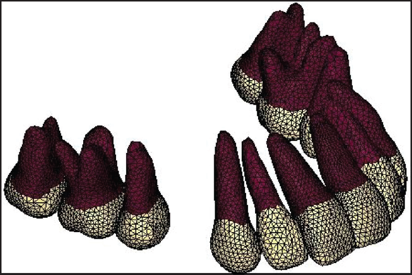
Construction of the Geometric Model
Using the ANSYS 12.1 version software, this geometric model was converted into finite element model (Figures 1 and 2, Table 1). Four models considering the biological properties of tooth and periodontium were created. 0.022″ × x 0.028″ standard edgewise brackets were attached to the teeth so that the midpoint of the brackets overlapped the FA point on the surface of the crowns. The teeth were connected by full-dimensional archwire [19″ × 25″ S.S.] from the labial side. A hook was located between the brackets of the maxillary lateral incisor and canine on the archwire for application of force.
Geometric Model of Maxillary Teeth Developed in HYPERMESH Software
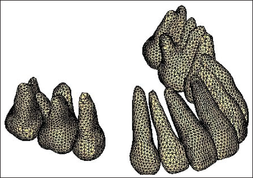
Conversion of Geometric Model into Finite Element Model in ANSYS Software
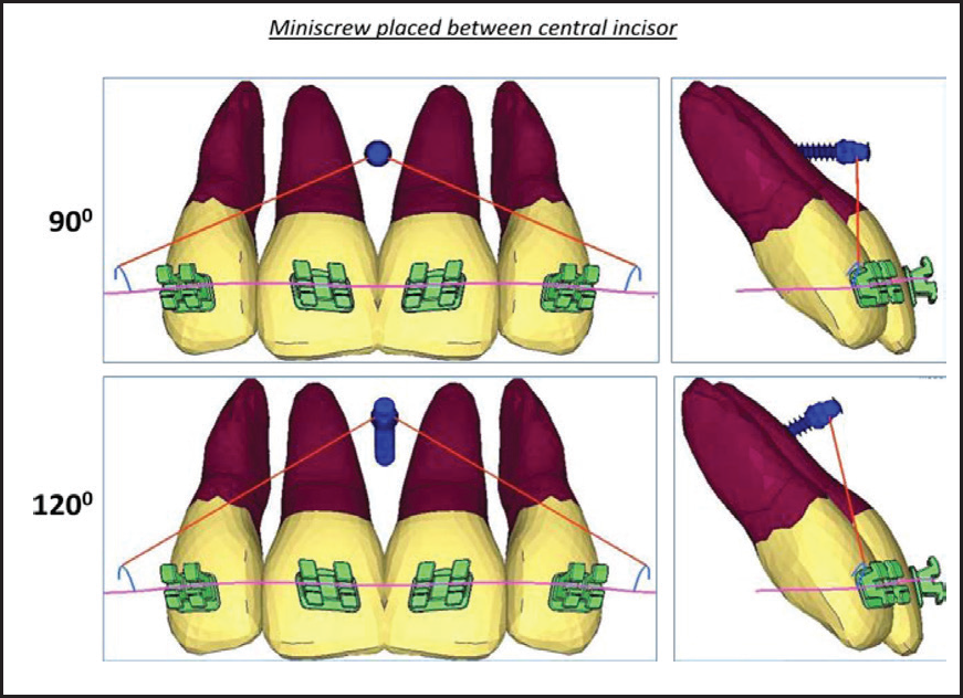
Finite Element Models With Mini-implants Placed in Between the Maxillary Central Incisor at 90° and 120°
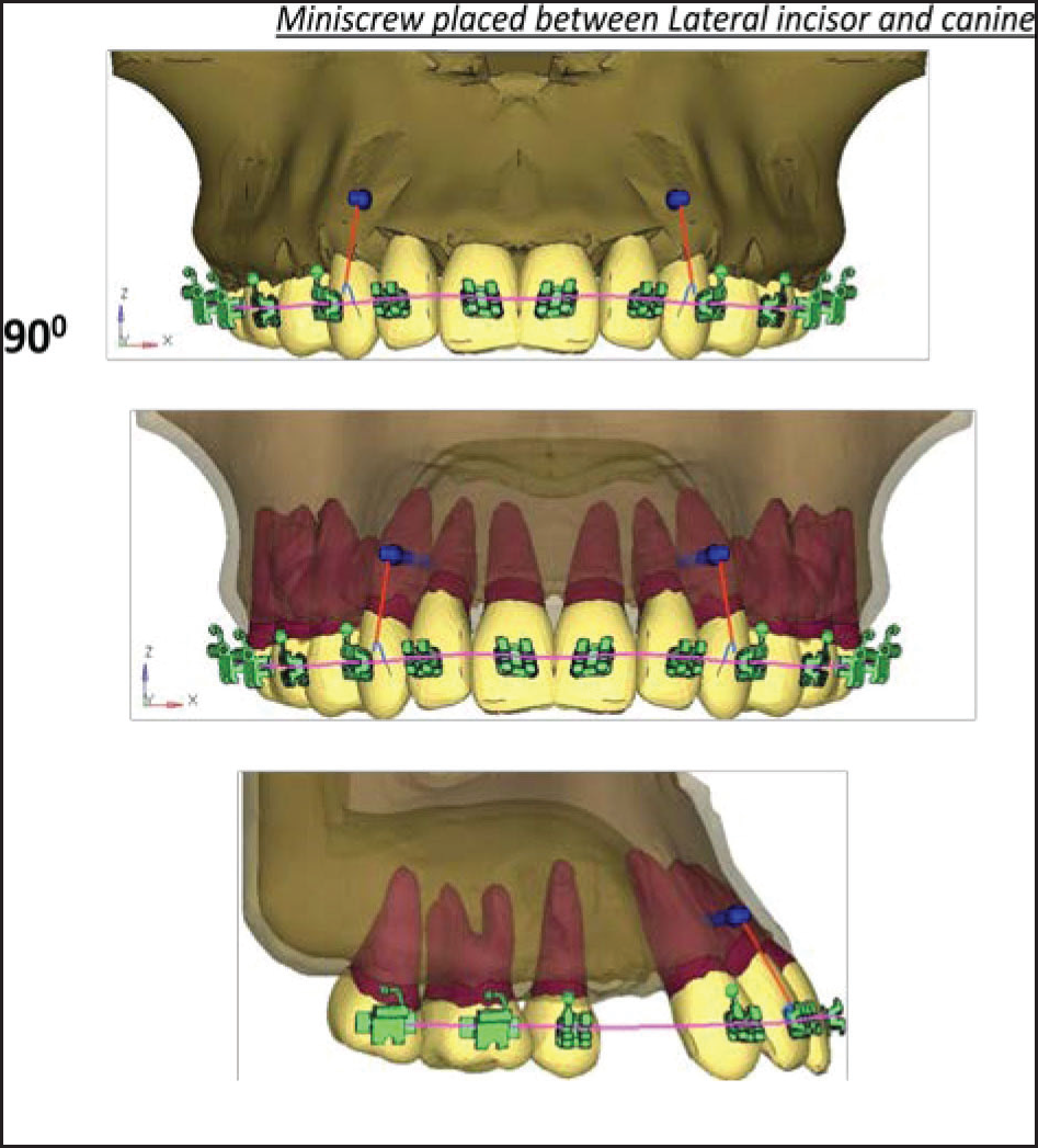
Finite Element Models With Mini-implants Placed in Between the Maxillary Lateral Incisor and Canine at 90°
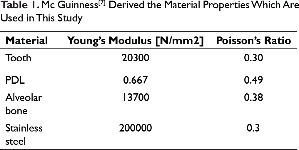
Mc Guinness[7] Derived the Material Properties Which Are Used in This Study
Finite Element Models With Mini-implants Placed in Between the Maxillary Lateral Incisor and Canine at 120°
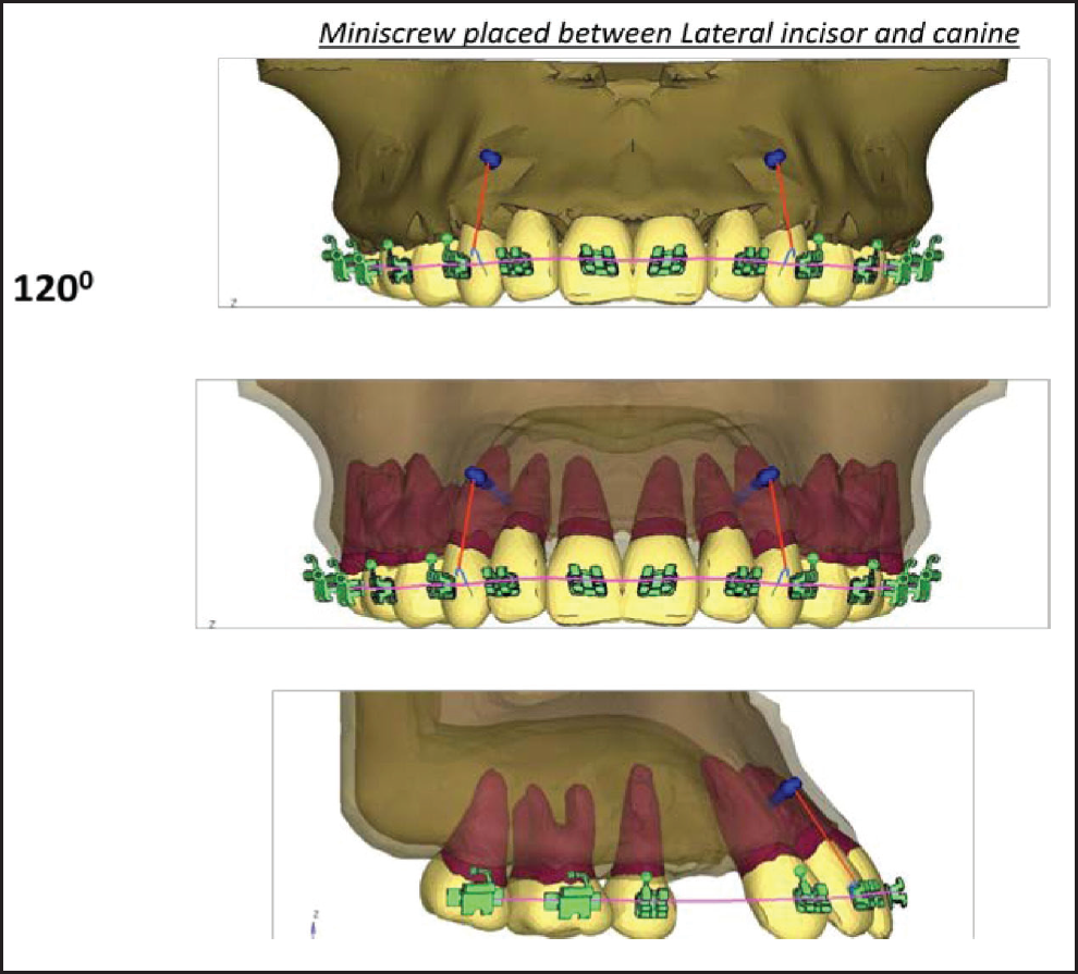
Mini-implants [1.5 × 8mm] were placed between the roots of the 2 central incisors and bilaterally between the lateral incisor and the canine. Mini-implants were placed at 4 mm from the gingival margin. The mini-implants were inserted at both 90° and 120° in the coronal plane at both the positions mentioned above (Figures 3-5).
Application of Forces
Anterior intrusion was done with force vectors from different positions and angulations of the mini-implants resulting in the following 4 cases:
Single central implant at 90° angulation Single central implant at 120° angulation Bilateral implants at 90° angulation Bilateral implants at 120° angulation
Overall, 100 gm force was applied.
Under these conditions, FEA was performed and the initial vertical displacement of the maxillary anterior teeth and Von Mises stress distribution along the root surface were evaluated. Stress and displacement were presented as different color bands, which represented different magnitudes. The red color column of the spectrum indicated the highest level followed by different shades of orange, yellow, green, and blue, while dark blue represented decreasing levels of stress.
Results
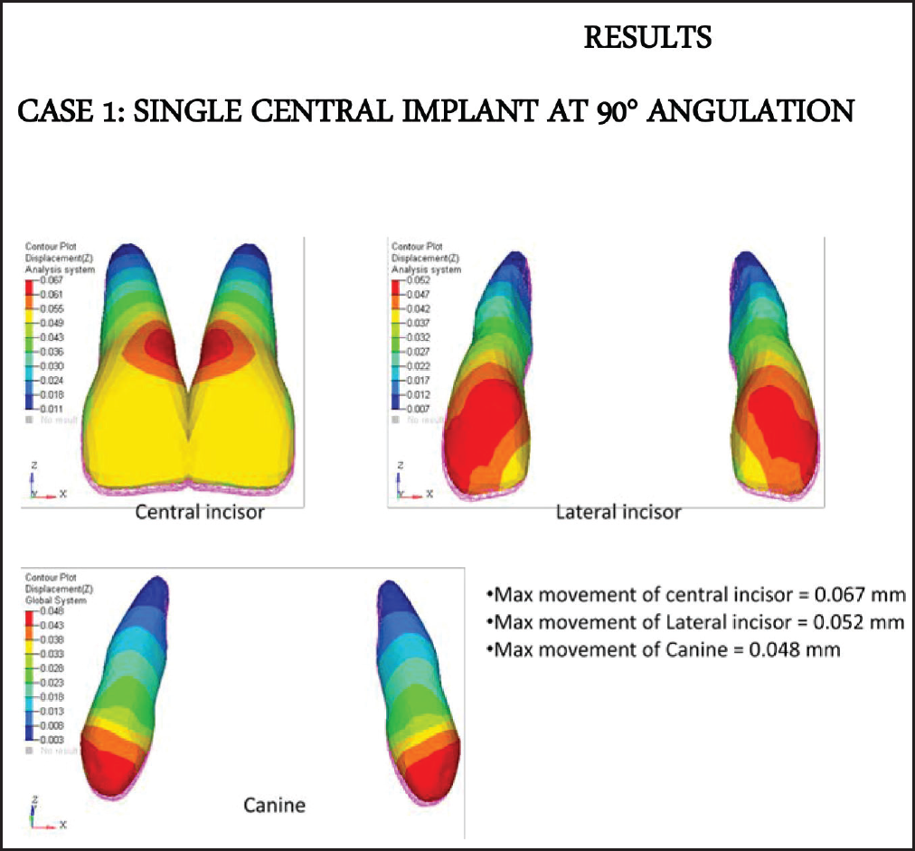
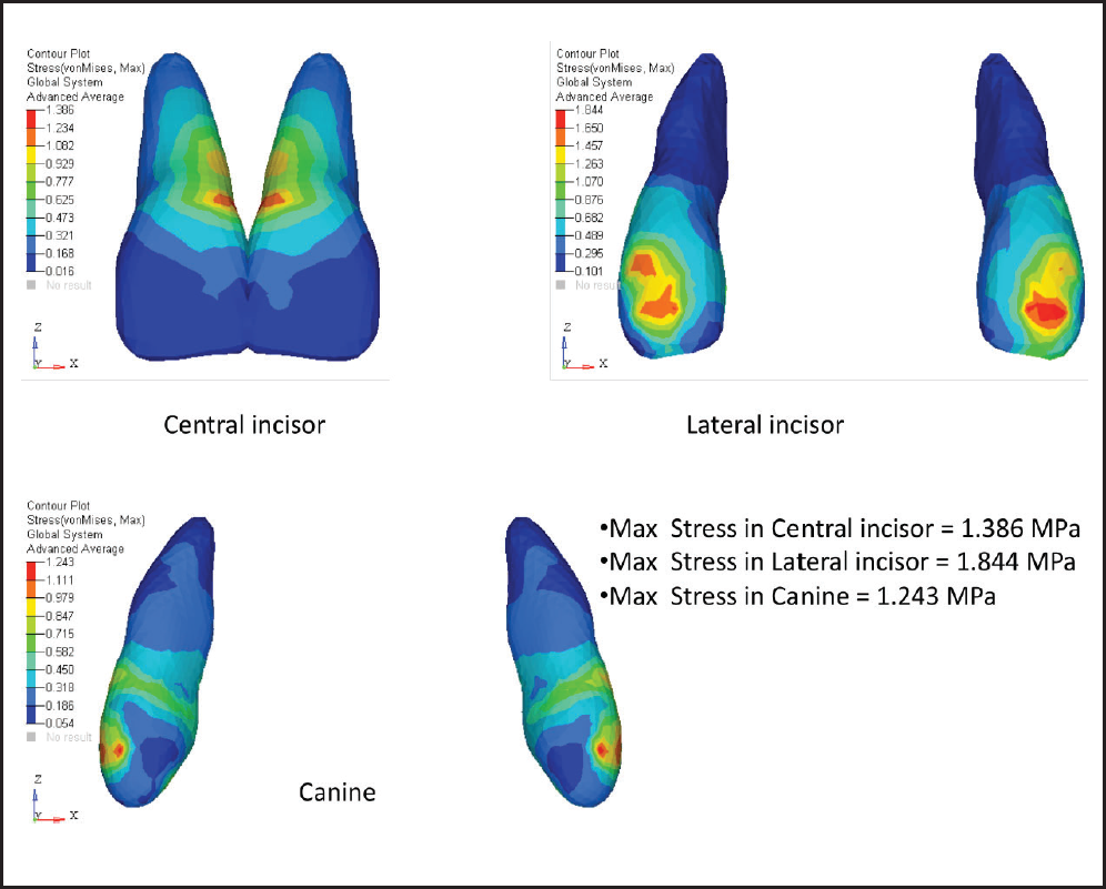
Case 1: Single Central Implant at 90° Angulation
From the diagrams (Figures
Displacement of Anterior Teeth in mm (Case 1)
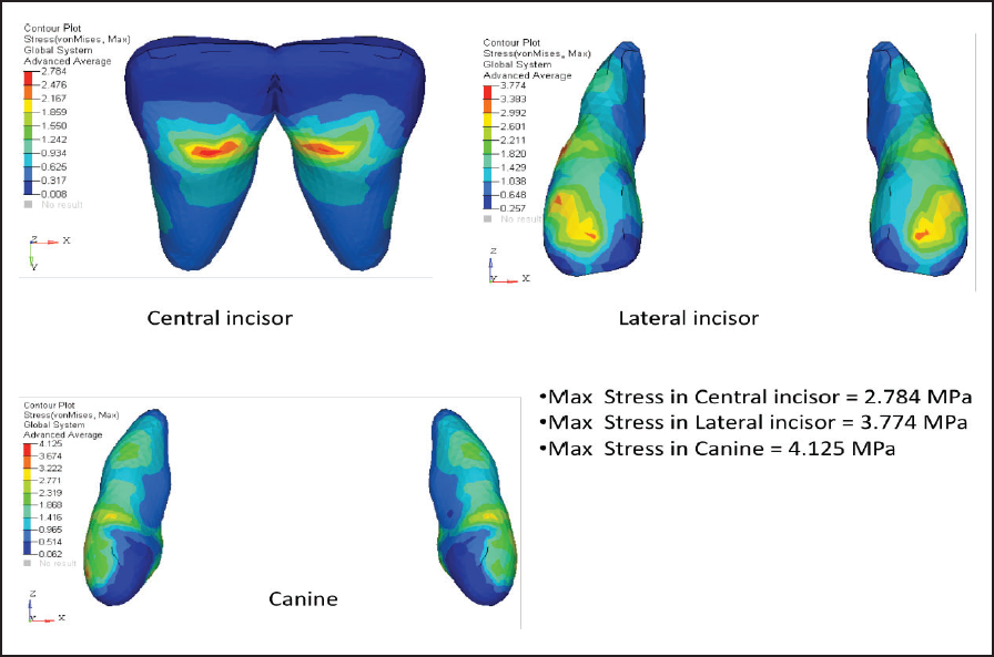
Von Mises Stress Contours in Anterior Teeth (MPa)
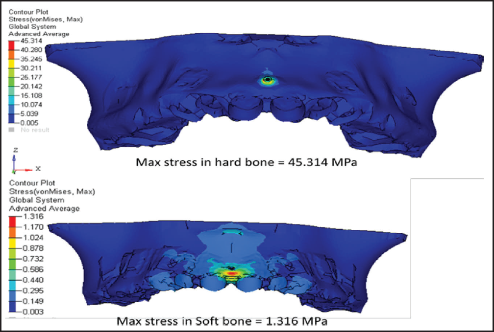
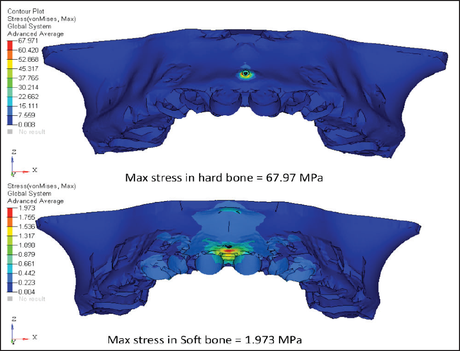
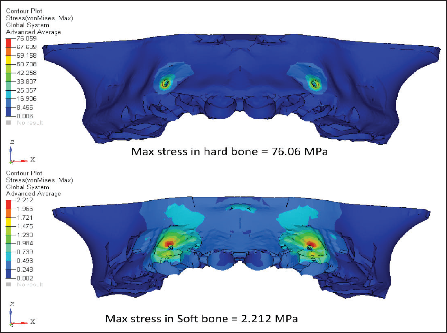
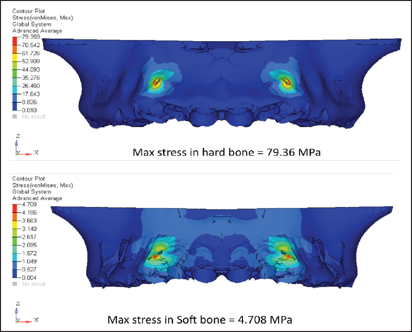
Von Mises Stress Contours in Hard and Soft Bone (MPa)
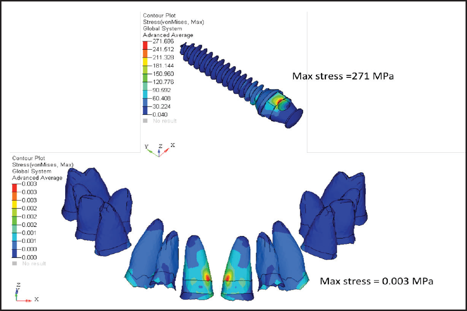
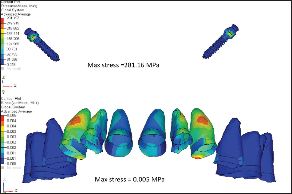
Von Mises Stress Contours in PDL and Mini-implant (MPa)
Pink netted image is the position of teeth before loading, and colored pattern teeth is the position after loading; therefore, the central incisor shows the maximum displacement which keeps on decreasing as moving distally towards the canine.
The maximum stress is concentrated in the incisor region.
The maximum stress in mini-implant is concentrated at the insertion site.
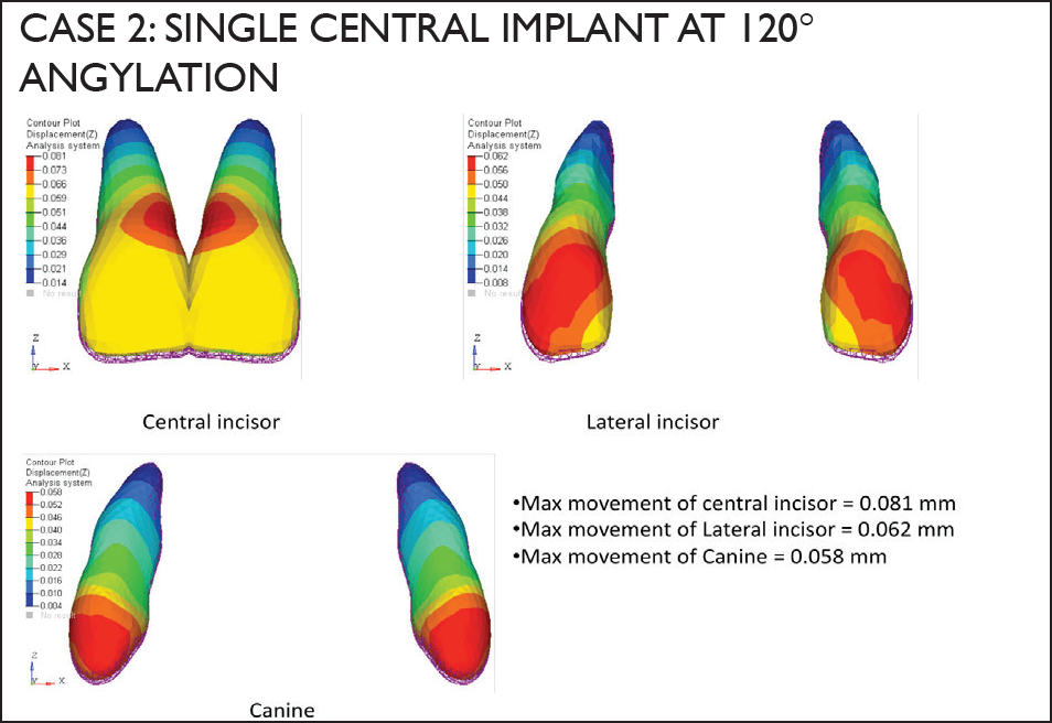
Displacement of Anterior Teeth in mm (Case 2)
Von Mises Stress Contours in Anterior Teeth (MPa)
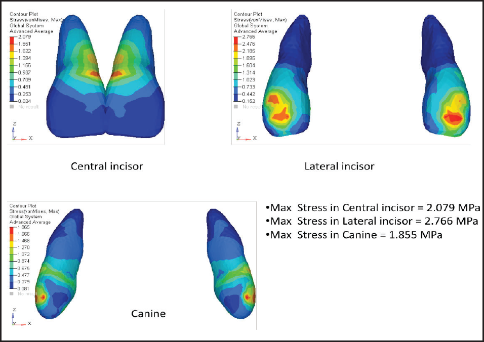
Case 2: Single Central Implant at 120° Angulation
From the diagrams (Figures 10-13), we can conclude:
Von Mises Stress Contours in Hard and Soft Bone (MPa)
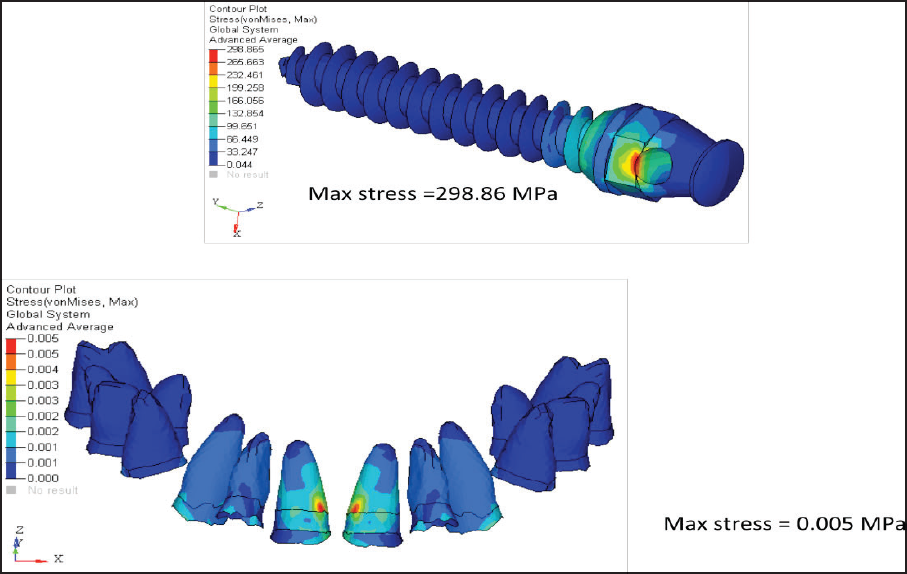
Von Mises Stress Contours in PDL and Mini-implant (MPa)
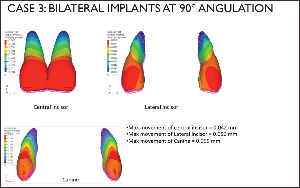
Displacement of Anterior Teeth in mm (Case 3)
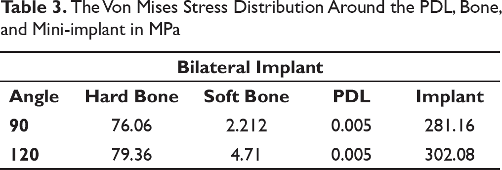
The Von Mises Stress Distribution Around the PDL, Bone, and Mini-implant in MPa
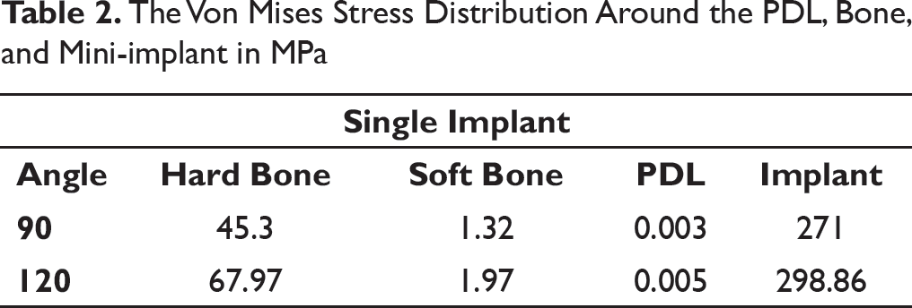
The Von Mises Stress Distribution Around the PDL, Bone, and Mini-implant in MPa
The Amount of Displacement in mm of Central Incisor, Lateral Incisor, and Canine
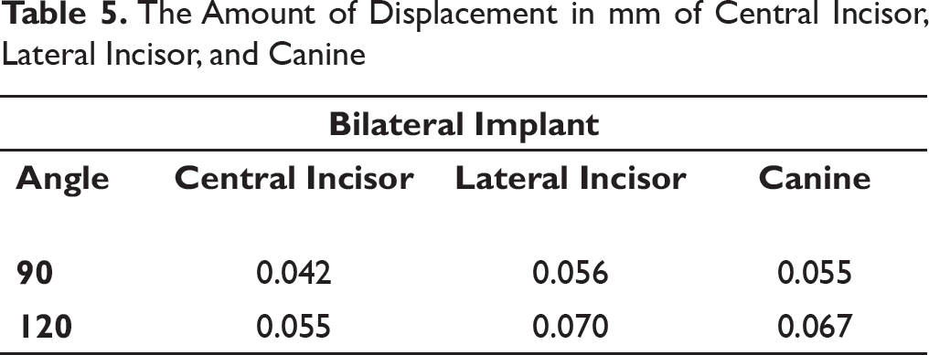
The Amount of Displacement in mm of Central Incisor, Lateral Incisor, and Canine
Pink netted image is the position of teeth before loading, and colored pattern teeth is the position after loading.
As the miniscrew angulation increases, the amount of intrusion also increases.
Therefore, the central incisor shows maximum displacement which keeps on decreasing as we move distally towards the canine.
The maximum stress is concentrated in the lateral incisor.
The stress increases with increase in the angulation of the mini-implant.
The maximum stress in mini-implant is concentrated at the insertion site.
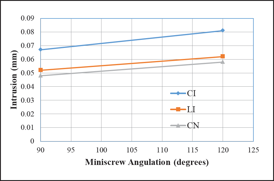
Result summary of single implant at the center (Tables 2 and 4, Graphs 1 and 2):
Graph showing movement variation in millimetres [mm] at 90° and 120° with single mini-implant at center
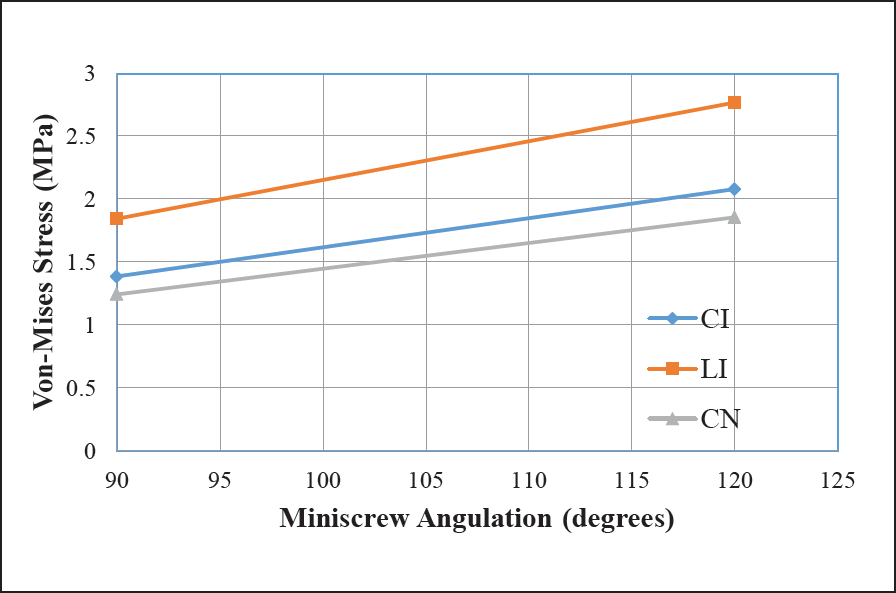
Graph showing stress variation in MPa at 90° and 120° with single miniimplant at center
As the miniscrew angulation increases, the amount of teeth intrusion also increases.
Maximum intrusion happened for central incisor with miniscrew at 120° angulation and is around 0.081 mm.
Similarly minimum intrusion happened for canine and is around 0.048 mm.
Stresses also increase with increase in miniscrew angulation.
Maximum stress seen around implant during 120° angulation was 298.86 MPa.
Stresses are concentrated in the miniscrew insertion region.
Von Mises Stress Contours in Anterior Teeth (MPa)
Von Mises Stress Contours in Hard and Soft Bone (MPa)
Von Mises Stress Contours in PDL and Mini-implant (MPa)
Case 3: Bilateral Implants at 90° Angulation
From the above diagrams (Figures 14-17), we can conclude:
Pink netted image is the position of teeth before loading and colored pattern teeth is the position after loading. Thus, we can see that the lateral incisor shows the maximum displacement. The maximum stress concentrated in the canine region gets evenly distributed towards the midline. The stresses are distributed in the mini-implant insertion area.
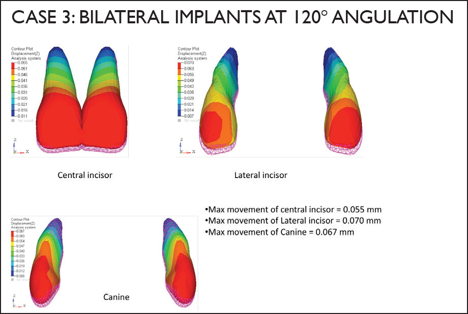
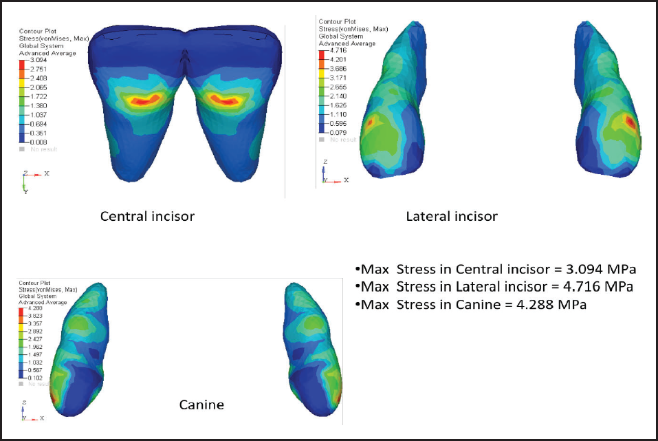
Case 4: Bilateral Implants at 120° Angulation
From the above diagrams (Figures 18-21), we can conclude:
Pink netted image is the position of the teeth before loading and colored pattern teeth is the position after loading. Thus, we can see that lateral incisor shows the maximum displacement. The central incisor shows the minimum amount of intrusion. The amount of intrusion increases as the angulations of the mini-implants increase. The maximum stress concentrated in the canine region gets evenly distributed towards the midline. The stresses are distributed in the mini-implant insertion area.
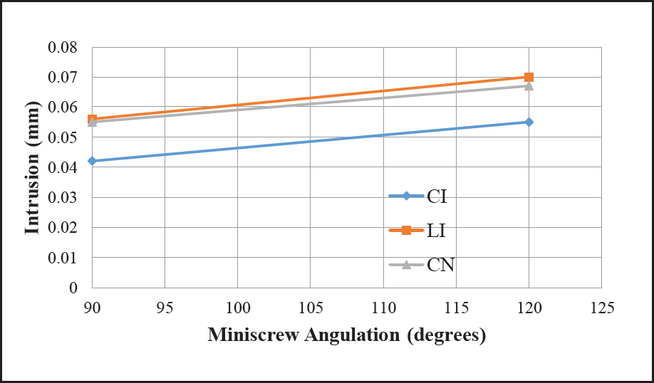
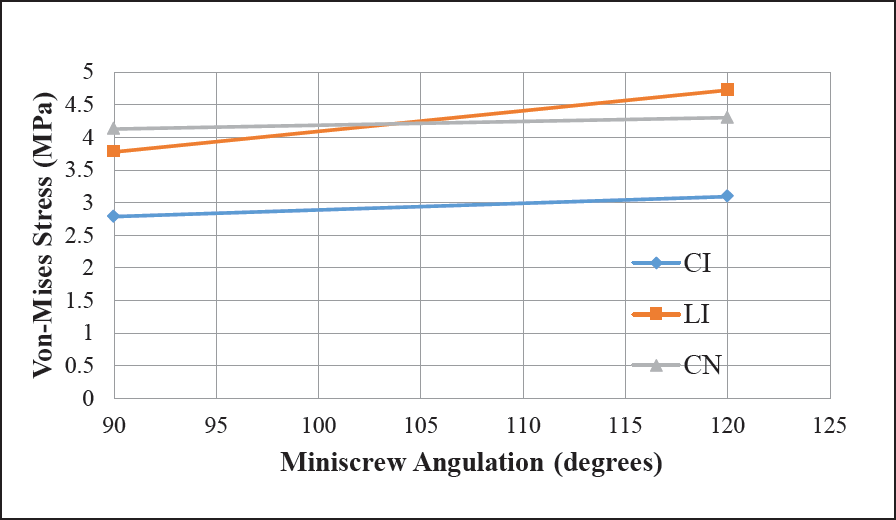
Result summary of bilaterally placed implants (Tables 3 and 5; Graphs 3 and 4):
Displacement of Anterior Teeth in mm (Case 4)
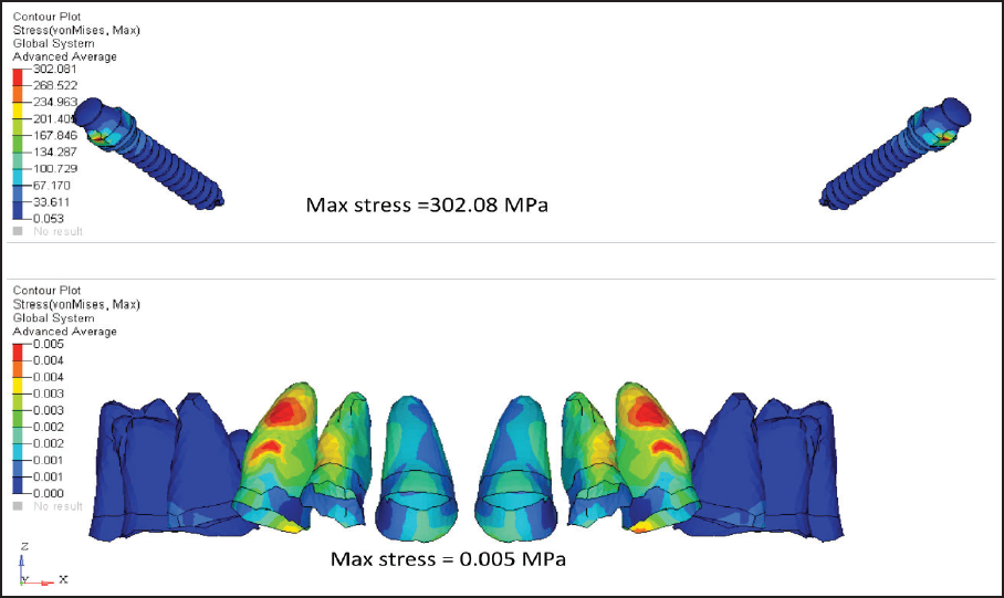
Von Mises Stress Contours in Anterior Teeth (MPa)
Graph showing movement variation in millimetres [mm] at 90° and 120° with bilaterally placed mini-implant
Graph showing stress variation in MPa at 90° and 120° with bilaterally placed mini-implant
As the miniscrew angulation increases, the amount of teeth intrusion also increases.
Maximum intrusion happened for lateral incisor with miniscrews at 120° angle and is around 0.07 mm.
Similarly minimum intrusion happened for central incisor and is around 0.042 mm.
Stresses also increase with increase in miniscrew angulation.
Maximum stress seen around implant during 120° angulation was 302.08 MPa.
Stresses are distributed over the miniscrew insertion regions.
Von Mises Stress Contours in Hard and Soft Bone (MPa)
Von Mises Stress Contours in PDL and Mini-implant (MPa)
Discussion
With the increasing knowledge about dentistry and aesthetics, orthodontics has become one of the most common modes of dental treatment. Due to the everyday development occurring in this field, it becomes difficult to comprehend the complex forces and movement generated as a part of the treatment. One has to simplify the methods and minimize the force interplay for predictable outcomes. The aim of further research is to minimize treatment time, complexities, and patient discomfort with reliable results. A number of studies have been conducted in the earlier period to understand the correlation between the forces and stress distribution on tooth and its supporting structures. The various methods such as FEM, photoelectric studies, and laser holographic techniques were used.
Each of these techniques possesses innate advantages and disadvantages. Few disadvantages of this technique are that it is a complex method. It requires lots of computer time and skills. Also complete oral environment could not be generated. Apart from these disadvantages, FEM has many advantages over other methods highlighted as a non-invasive, 3-dimensional study. It has the ability to include heterogeneity of the tooth structures, and physical properties of the material are not affected by reproducibility. The loads, which can be applied at different directions and locations, help in measuring the actual displacement and stress experienced in the area. The models can be magnified infinitely both in terms of actual volumetric construction itself and the mathematical variability of its material parameters. Hence, FEM was used to determine the stress distributed during maxillary anterior intrusion under different conditions of the mini-implant.
Increased overbite is nowadays a very common problem encountered by the orthodontist. Therefore, before treating it, the causative factor should be determined. The cause could be either due to reduced lower face height, lack of eruption of the posterior teeth, or overeruption of the anterior teeth. Therefore, the treatment plan should be decided by either extrusion of the posteriors or intrusion of the anteriors. It is widely accepted that correction of deep bite by extrusion of posterior teeth, although is carried out commonly, is difficult to maintain and even less stable when it is performed on nongrowing adult patients and patients with low freeway space or interocclusal clearance at rest, than when it is attempted on those with appreciable growth remaining.8, 9, 10 Hence, intrusion of the anteriors is the better choice in those patients.
Conventional methods for intrusion such as K-SIR, 3-piece intrusion arch, utility arch11, or an intrusion base arch 11 are still frequently used for deep bite correction. But this system creates a force to extrude the molars.12, 13 In patients having high mandibular plane angle, the molar extrusion is not advisable, as extrusion will cause downward and backward rotation of mandible. The J-hook headgear is used for incisor intrusion and depends on the head for anchorage, but it requires excellent patient cooperation. 14 To avoid these complications, mini-implants were used for true intrusion.
In the present study, 2 positions of implant were selected—one at the midline between 2 central incisors and one bilaterally between lateral incisor and canine. As en masse intrusion of 6 teeth was done, the center of resistance had to be determined. According to Ha MH and Son WS, as the number of teeth increased distally, the center of resistance also shifted distally. Therefore, the center of resistance for the 6 teeth during anterior intrusion lies between the maxillary lateral incisor and canine. 15 In single implant cases, the point of force application to the attachment produced more forces in the oblique direction than in the axial direction to the long axis of the tooth. On the other hand, in bilateral implant cases, more forces were produced in the axial direction that is parallel to the long axis of the tooth. At 90°, the implant undergoes tensile shear stresses like a beam supported at one end. At 120°, the stresses experienced by the implant are more in tensile nature. It will tend to elongate more than bending movement. The highest strength of the implant will be seen, however, when the implant experiences only the tensile stresses. This is possible only at 180° to the long axis of the implant. Although, theoretically possible, it is practically impossible during orthodontic treatment.
In single implant cases, the stress gets concentrated at the center, which is unfavorable. On the other hand, in bilateral cases, the stress does not get concentrated at the center but gets evenly distributed and is favorable.
An insertion angulation of the implant is important for cortical anchorage, safety of patient, and for biomechanical consideration. With proper angulations, risk of damaging roots is reduced and contact between mini-implant and bone can be increased. An angulation of the mini-implant placed to the bone also plays a key role in the amount of stress and the amount of displacement that occurs during the intrusion.
From the above results, the displacement seen with 90° angulation in the single implant case is less compared to the displacement with 120° angulation case for all the 6 maxillary anterior teeth. Also, in the bilateral implant case, the Von Mises stress is less when the 90° angulation case is compared to the 120° angulation case. But in bilaterally placed implant the stress gets distributed evenly in the anterior region. The stress in 90° cases seems to be concentrated at the center. However, the amount of displacement seen with 120° is more compared to 90° at both positions of implant.
The mini-implant used in orthodontics is mechanically retained and to increase the stability, the contact area between mini-implant and bone should increase. Hence, the implants should be inserted obliquely to the bone in the coronal plane for better stability and to withstand the loading conditions.
Placing an implant at an angulation also prevents the root damage. Hence, placing implant at 120° is preferable compared to placing it at 90°. The result also shows that as the angulations of the mini-implant to the bone increase, the amount of intrusion also increases. Therefore, for better results and stability, the implant should not be placed perpendicular to the bone.
The most common complication encountered during maxillary anterior intrusion is apical root resorption. Previous studies suggest that external apical root resorption is more likely to be seen during treatment, when forces at the apex exceed the threshold and reparative ability of the periapical tissues.16, 17 If continuous heavy forces are used, then the risk of resorption increases. Accordingly, extremely light forces of (15-25 gm) should be used to produce appropriate pressure within the periodontal ligament.13, 17
Research shows that comprehensive orthodontic treatment causes increased incidence and severity of root resorption and the heavy forces are highly harmful. As the intrusive forces are applied to the tooth, the initial distribution of the forces around the periodontal ligament elongates the principal fibers causing concentration of forces around the periapical area. As the area is very small, the increase in force value is very fast and reaches quickly to a dangerous level. As the level increases beyond threshold, the tooth movement starts, but if the forces are heavy, hyalinization and subsequent root resorption start. Heavy force application produces more significant orthodontically induced inflammatory root resorption than light force application.18, 19 However, the amount of stress generated at the apices to initiate apical root resorption is significantly correlated to the amount of intrusion and the duration. As it can be assumed that the range of stresses exerted by the blood in the capillary vessels (0.0026 N/mm2) help us to predict the onset of bone remodeling. 20
Limitations of the Study
During treatment, even with perfect mechanics and accurate force systems, after the initial tooth movement, the biomechanical effect of the force system changes, and modifications are required. Any study using static finite element analysis only simulates the initial tooth movement in the periodontal membrane and the initial stress distribution along the root surfaces. At the present state of our knowledge, when the same loading conditions continue, it is impossible to derive what precisely happens over a certain length of time. This drawback also applies to the present investigation.
The present study can also be done by adding one more angulations of 60° and then can be compared with 90° and 120°, to check for a better angulation for maximum amount of intrusion with minimum amount of stress.
Conclusion
Stresses measured on the teeth are less and distributed more evenly, when the point of force application is bilateral where the direction of force is oblique. It was also observed that the stress increases with increase in the angulation of the implant. Concentrated stresses are not favorable as they can increase the risk of bone and root resorption.
Therefore, from the present study, we can conclude that placing implant bilaterally at 120° gives the best intrusion.
Footnotes
Declaration of Conflicting Interests
The authors declared no potential conflicts of interest with respect to the research, authorship, and/or publication of this article.
Funding
The authors received no financial support for the research, authorship, and/or publication of this article.