
Abstract
Background
To compare the biomechanical stability of a novel, C-shaped nickel–titanium shape memory alloy (SMA) implant (C-clip) with traditional cerclage wiring in the fixation of a Vancouver B1 (VB1) periprosthetic femoral fracture (PFF).
Methods
In total, 18 synthetic femoral fracture models were constructed to obtain unstable VB1 fracture with an oblique fracture line 8 cm below the lesser trochanter. For each model, the distal portion was repaired using a 10-hole locking plate and four distal bi-cortical screws. The proximal portion was repaired using either three, threaded cerclage wirings or three, novel C-shaped implants. Specimens underwent biomechanical testing using axial compression, torsional and four-point bending tests. Each test was performed on three specimens.
Results
The C-clip was statistically significantly stronger (i.e., stiffer) than cerclage wiring in the three biomechanical tests. For axial compression, medians (ranges) were 39 (39–41) and 35 (35–35) N/mm, for the C-clip and cerclage wiring, respectively. For torsion, medians (ranges) were, 0.44 (0.44–0.45) and 0.30 (0.30–0.33) N/mm for the C-clip and cerclage wiring, respectively. For the four-point bending test, medians (ranges) were 39 (39–41) and 28 (28–31) N/mm; for the C-clip and cerclage wiring, respectively.
Conclusion
Results from this small study show that the novel, C-shaped SMA appears to be biomechanically superior to traditional cerclage wiring in terms of stiffness, axial compression, torsion and four-point bending, and may be a valuable alternative in the repair of VB1 PFF. Further research is necessary to support these results.
Introduction
Periprosthetic femoral fractures (PFF) around, just below, or well below the tip of a well-fixed prosthesis (Vancouver type B1 [VB1] and C [VC]) are routinely treated with open reduction and internal fixation (ORIF). 1 Standard bi-cortical screws are generally efficient in distal fixations. 2 However, the biomechanical procurement of the proximal segment may be difficult because of the presence of cemented or cementless mantle of the hip prosthesis. Currently, there is no gold standard method for proximal portion fixations. Cerclage cables, allograft struts, and locking or non-locking uni-cortical screws are available options. Other options include, plate designs that allow bi-cortical fixation by directing offset locking screws tangentially around either side of the hip stem. 2
Cerclage wiring is the only implant that uses centripetal force to reduce and keep radially displaced fragments together. 3 Although it is a useful implant, it is regarded as a ‘limited use method’ because it is associated with many problems such as, blockage of blood supply, possibility of blood vessel damage, complicated surgical technique, prolonged operation time, and mechanical weakness as a stand-alone use. 4 However, it has garnered attention and interest due to the increasing numbers of PFF following hip arthroplasty, especially in the active aging population.1,5 We hypothesised that, if an implant was made in a partially opened C-shape and so did not wrap around the bone for 360 degrees, it would have the advantages of cerclage wiring fixation (i.e., centripetal force, wrapping the bone) and its disadvantages could be improved (i.e., circulation block, mechanical weakness, and risk of major vessel injury).
Therefore, we manufactured a C-shaped nickel–titanium shape memory alloy (SMA) implant (C-clip) that had super elasticity. The purpose of this current study was to compare the biomechanical stability of the novel, C-clip implant with traditional cerclage wiring in fixation of a synthetic femoral fracture model of VB1 PFF.
Methods
Fracture models
In total, 18 left artificial femurs (model #LD2386, SYNBONE, Switzerland) were prepared. The geometry for each femur was standard as per the manufacturer. Each femur was 450 mm in length, with mid-shaft mediolateral outer diameter 30 mm, mid-shaft anteroposterior diameter 26 mm, condylar width 85 mm, neck angle 122°, anteversion 15°, head diameter 48 mm, and intramedullary canal diameter 12 mm. An oscillating saw was used to create a 45-degree oblique osteotomy at an 8-cm distal midportion from the tip of the lesser trochanter (LT) for the fracture model. Our intention was to represent a VB1 PFF (Figure 1). To simulate the worst-case scenario of an unstable fracture pattern, an additional transverse osteotomy was added on the medial side 8 cm below the tip of the LT, where there was no bony contact across the fracture, and a gap was left across the fracture site. To make the same fracture model for all 18 femurs, cutting jigs to guide the osteotomy were prepared. The same fracture model was made by a single orthopaedic surgeon. The osteotomies were provisionally stabilized with a noncontact bridging curved femur shaft plate using bone holding forceps.

Fracture model of Vancouver B1 periprosthetic femur fractures. The Vancouver type B1 (VB1) femoral fracture model was designed using radiographs with left artificial joint replacement. An oscillating saw was used to create a 45-degree oblique osteotomy at an 8-cm distal midportion from the tip of the lesser trochanter (LT) for the fracture model. To simulate the worst-case scenario of an unstable fracture pattern, an additional transverse osteotomy was added on the medial side 8 cm below the tip of the LT, where there was no bony contact across the fracture, and a gap was left across the fracture site.
Constructs for femur fracture fixation
Proximal fixations of the femoral fracture models were randomly assigned to either cerclage wiring or C-clip implant as follows:
The novel C-shaped nickel–titanium shape memory alloy (SMA) implant (C-clip).
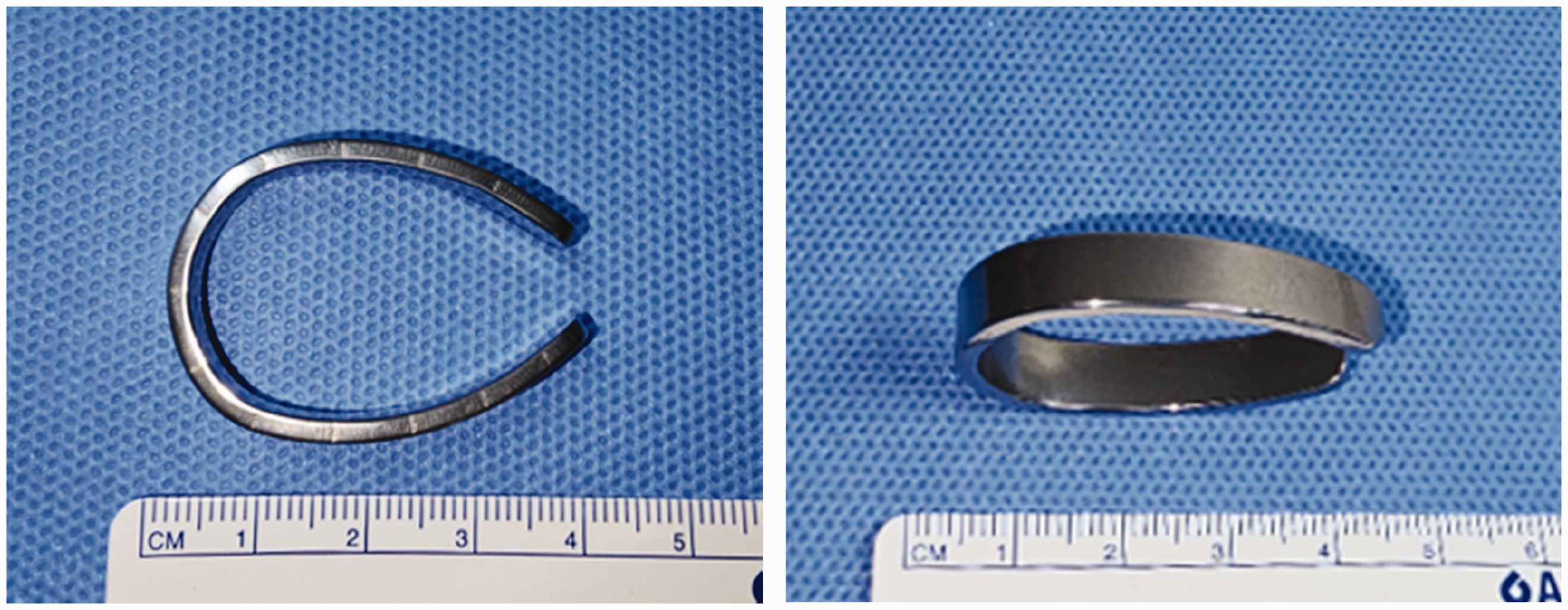
Figure 3 shows the C-clip set up with three pieces of implant applied proximally and the cerclage wiring setup with the three cables also at a proximal location. The distal portion was repaired using a 10-hole locking plate and four Ø 5.0-mm bi-cortical screws placed equally.
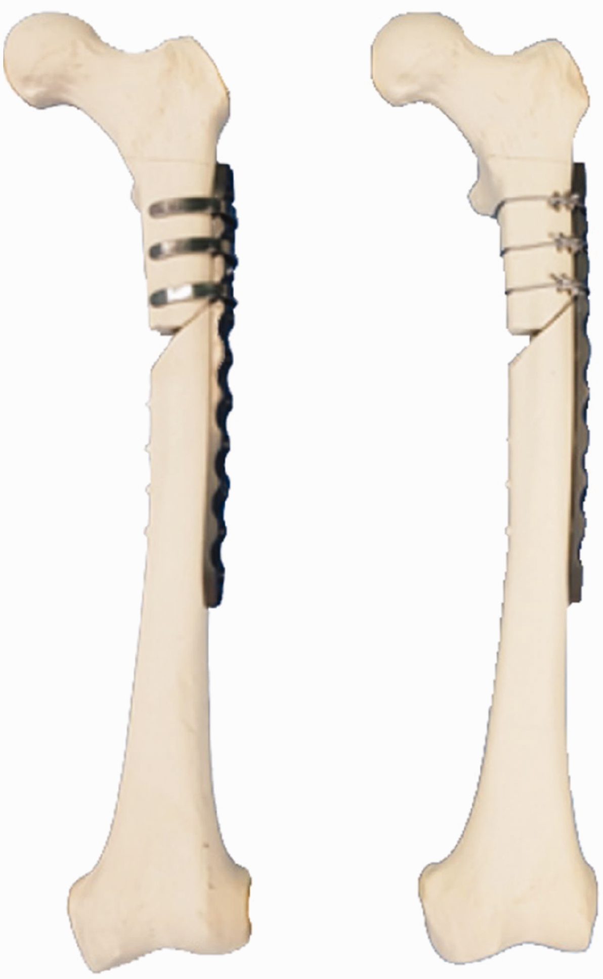
Constructs for the periprosthetic femur fracture fixation. (Left) The C-clip set up with three pieces of implant applied proximally. (Right) The cerclage wiring setup with the three cables at a proximal location. The distal location of the periprosthetic femoral fractures (PFF) was repaired with four Ø 5.0-mm bi-cortical screws placed equally.
Biomechanical stability
To evaluate the fixation force of the C-shaped implants in the in vivo environment, an experimental in vivo environment was constructed. For this, extruded thermal insulation boards, which have low thermal conductivity, were used to make an experimental chamber and two 300-W incandescent bulbs were fixed on both sides of the chamber to maintain a temperature of approximately 36.5°C. A pre-test was conducted to ensure that the test environment was maintained at 36–37°C for 30 min.
The distal condyle of all femoral bone models was removed 30 cm distal from the greater trochanter (GT) tip because an intact femur model might be broken at the femoral shaft during the loading test; using resin for fixation, the models were then mounted on a steel square holder. 7 A material testing machine (MTS 858 Mini Bionix Biomechanical Test System, MTS Systems Corp., USA) with a 25 kN load cell was used for all biomechanical tests and loading was applied to the femoral head through the flag jig. The axial compression, torsion and four-point bending tests are shown in (Figure. 4). Each test was performed on three specimens.

Mechanical test modes. The setup for the (a) axial compression, (b) torsion, and (c) four-point bending tests to measure stiffness. Compression tests were performed at 25° in a vise with adduction in the frontal plane and neutral position in the sagittal plane to simulate the one-legged stance. Torsion tests were performed with adduction in the frontal plane with the long axis of the femur horizontal. The four-point bending test was performed with the specimen positioned in between the contact points, allowing free bending movement.
Compression tests were performed at 25° in a vise, with adduction in the frontal plane and neutral position in the sagittal plane to simulate the one-legged stance. 7 For the axial compression tests, a preload of 100 N at a rate of 20 N/min was loaded to each specimen to ensure complete contact between the femoral head and the test equipment. 7 Subsequently, a vertical force was applied at a speed of 10 mm/min until the construct failed, while recording load–displacement curves. A clinical failure was defined as a sudden drop in the observed load-displacement curve or, displacement of the proximal fragments in excess of 10 mm.7,8
Torsion tests were performed in a vise at 25° with adduction in the frontal plane and the long axis of the femur horizontal. For the torsion test, a support block was placed 220 mm from the loading point to minimize long-axis bending and the distal femur was fixed by a steel jig with screw. A preload of 50 N was applied to each bone model. Subsequently, a vertical force was applied at a speed of 8 mm/min (=0.005 rad/min) while recording load–displacement curves. 8 Thereafter, the load–displacement graph was converted into a moment–angular displacement graph. 9
For the four-point bending tests, intact bone models were used without removal of distal condyle. Biomechanical testing of each specimen was performed with the specimen freely positioned between the contact points, allowing free bending movement. The upper contact points were placed symmetrically between the lower contact points (i.e., loading span = 130 mm, support span = 50 mm). The test was conducted until the end of the plate of the tension surface touched the support roller. The vertical force was applied at a speed of 0.5 mm/min while recording load–displacement curves. Stiffness of the construct was defined as the slope of the load-displacement curve. The slope corresponded to the linear section within elastic deformation. In the torsion and four-point bending tests, all specimens remained within the linear elastic region to avoid permanent specimen damage, as demonstrated in a previous study.8,10
Statistical analysis
Data were analysed using the Statistical Package for Social Sciences (SPSS) for Windows version 22, released 2013 (IBM Corp., Armonk, NY, USA). All tests were two-sided and a P-value <0.05 was considered to indicate statistical significance. Wilcoxon rank-sum test was used to assess differences between the fixation method variables.
Results
There were no observed failures of the specimens and at no point was fixation lost or deformed. A comparison of the stiffness of the model using two different fixation methods (i.e., C-clip or cerclage wiring) in the three types of biomechanical tests (i.e., compression, torsion and four-point bending) is presented in Figure. 5 and Table 1. The C-clip was stronger (i.e., stiffer) than cerclage wiring in the three tests. For axial compression, medians (ranges) were 39 (39–41) and 35 (35–35) N/mm, for the C-clip and cerclage wiring, respectively (P < 0.05). For torsion, medians (ranges) were, 0.44 (0.44–0.45) and 0.30 (0.30–0.33) N/mm for the C-clip and cerclage wiring, respectively (P < 0.05). For the four-point bending test, medians (ranges) were 39 (39–41) and 28 (28–31) N/mm; for the C-clip and cerclage wiring, respectively (P < 0.05).

Results of biomechanical testing. (a) Axial compression test; (b) torsion test and (c) four-point bending test.
Results of the biomechanical testing.

Data are expressed as, mean ± standard deviation, or medians (25th, 75th percentiles).
Discussion
Our study demonstrated notable improvements in compressive, torsional, and bending strength associated with the partially opened C-shaped SMA implant (C-clip) for fixation of the proximal segment compared with traditional cerclage wiring. Although the C-clip has less wrapping area to the bone than the cerclage cable, the holding stiffness appears stronger. We believe that this is due to the shape of the SMA implant. Almost all metals have a ductile property, and so they tend to loosen slightly over time from the initial fixation. In particular, cerclage wiring has a natural tendency to slip and loosen when any part of the bone tapers. 11 Although the novel C-clip has not been evaluated fully, we believe that, long-term it will hold the bone and plate tightly together. While direct comparisons between C-clip and cerclage wiring have not previously been made, fixation devices using SMA for PFF have been studied in the past under laboratory settings and in pilot clinical trials, and have yielded relatively favourable outcomes.6,12,13 These findings align with our results.
Cerclage wiring has several advantages and disadvantages related to the wrapping of the cable around the bone. For example, tension in the cable can pull radially displaced fragments together, an advantage that nails nor screws can offer. However, the 360-degree wrap around the bone has the potential for nerve and blood vessel damage.14–16 By contrast, the C-clip does not require a 360-degrees wrap and so avoids large vessel and nerve injury and so, has advantages over cerclage wiring. In addition, the C-clip will enable early rehabilitation because unlike cerclage wiring, it preserves the linea aspera and so is beneficial for the movement of thigh muscles. Furthermore, using a C-clip for fixation requires minimal skin incision and dissection. A large dissection site can result in prolonged surgical time, increased bleeding, and an increased likelihood of surgical site infection. Although some wire clamps have been developed that require minimally invasive procedures, they have to be used under fluoroscopy which will depend on the surgeon's experience. 17 Nevertheless, the C-clip is not without disadvantages. For instance, to obtain the C-shape, it is necessary to have high and low-temperature conditions. Therefore, it is necessary to develop a heat conduction tray using electricity.
Treatment of PFF following hip arthroplasty presents a major clinical challenge in orthopaedic surgery. 18 Patients with PFF are typically elderly and have varying degrees of osteoporosis and medical comorbidities. Fixation in these individuals is difficult because of the hip stem and poor bone quality. The results of our study suggest that the partially wrapped implant (i.e., the C-clip) may have the same or better holding power as 360-degree cerclage wiring methods in these patients.
Our study had several limitations. Firstly, we did not insert a hip stem. Several previous studies have performed biomechanical tests of PFF using cemented hip stems.2,10,19,20 However, we were of the opinion that using a hip stem would introduce more variables, such as the femoral stem position and cementing technique, and increase costs. In addition, we believe that the presence, or absence, of a hip stem will affect both groups equally. This hypothesis is supported by another study where biomechanical tests were performed without inserting a hip stem. 21 Secondly, we used synthetic bones to avoid discrepancies associated with cadaveric tissues. Nevertheless, synthetic models have been proven to be valuable in biomechanical studies involving fracture fixations because of their relatively low cost and reduced level of variability between specimens. 22 The synthetic models have been designed to represent average geometry and accurately match ideal bone properties. 23 Indeed, because of their uniformity, synthetic bones generally show lower standard deviations in variables assessed compared with cadaveric specimens. 24 Thirdly, our study did not include a control group using uni- or bi-cortical screws. This is in contrast to other studies that have compared experimental methods of fixation. However, we believe that our results have relevant clinical implications for the treatment of unstable VB1-type PFF. Fourthly, we had a small sample size. While previous authors have typically used more than five specimens per test group, the current study was limited to three specimens per construct group. This yielded a low statistical power to detect statistical differences between the test groups. Nevertheless, even with our small sample size, we observed statistical differences between. Finally, we were unable to simulate all of the physiologic force components experienced in a femur when standing or walking. Instead, we used isometric loading modes, such as axial compression, torsion and four-point bending. This makes it easy to identify if specific modes cause instability, but it may be that these constructs do not occur in vivo. 24
An ideal implant should not only maintain prosthesis stem stability but also provide stable fixation of poor-quality bone around the prosthetic stem. 6 Our study shows that partially opened C-shaped implant made with SMA (the C-clip) had superior strength in axial compression, bending, and torsion than traditional cerclage cable. Although the novel C-clip will require further assessments before it is used clinically, it is encouraging that the results from our biomechanical tests showed that the implant exhibited superior stiffness to the traditional cerclage wiring system.