
Abstract
While both autonomous and wearable robots can assist humans in load-carriage tasks, existing autonomous systems face challenges in real-world autonomy and endurance, whereas current wearable systems have shown limited effectiveness in improving human walking efficiency. This paper introduces the Centaur robot, an innovative wearable human augmentation robot that integrates human intelligence with robotic strength for collaborative load-carriage walking. The Centaur robot comprises two independent three-DoF robotic legs and a robotic torso, coupled with the human via a passive softening elastic mechanism, forming a human-Centaur quadruped system. This configuration optimizes vertical load distribution and provides horizontal forward force acting through the center of mass of the human during walking. The compliance-based interaction model established through the elastic mechanism enables dynamic decoupling of the human-Centaur system, allowing the Centaur to be modeled independently. To achieve coordinated locomotion and interaction force control, a novel loco-interaction control strategy is proposed. To further enhance the traversability to varying terrains, a terrain-adaptive swing leg controller is developed to generate a terrain-specific swing trajectory. Experimental evaluation results demonstrate that the Centaur robot effectively adapts to varying human walking directions and speeds while seamlessly collaborating with the human to traverse diverse terrains. In the load-carriage experiment (n = 5), the Centaur robot achieved a load-sharing ratio of 52.22% ± 15.52%, reduced the metabolic cost by 35.16% ± 4.95%, and improved lateral gait stability compared to a regular backpack when carrying a 20 kg load, equivalent to 28.8% ± 4.03% of the participants’ body weight.
Keywords
Introduction
Load-carriage walking on diverse terrains is a common activity in daily life. Walking with heavy loads on the back causes high pressure and substantial stress on the human body and joints (Boffey et al., 2019), thereby increasing the metabolic cost of the human. Due to the characteristics of human bipedal walking, prolonged load-carriage can lead to various disorders and musculoskeletal damage (Orr et al., 2014), particularly negative effects on the spine (Orloff and Rapp, 2004). To mitigate these negative impacts on humans, two distinct technological strategies have emerged. One involves autonomous systems (Leong and Ahmad, 2024) that transport loads independently of the human, while the other relies on wearable robotic systems (Li and Li, 2023) that integrate with the human body to provide assistance.
Autonomous robots, including quadrupeds (Raibert et al., 2008; Jin et al., 2022), humanoids (Kim et al., 2020; Radosavovic et al., 2024), and aerial drones (Villa et al., 2020), are being actively explored as load-transport solutions without direct human involvement. These systems have demonstrated impressive mobility in structured environments and exhibit promising potential for replacing human effort in load-carriage. However, the deployment of such autonomous systems in real-world scenarios remains constrained by several factors. First, due to limitations in perception, path planning, and terrain adaptability, autonomous robots struggle to navigate reliably in complex environments where a prior map is unavailable (Lee et al., 2024). Teleoperation can mitigate these issues but increases the cognitive burden on human operators and reduces overall efficiency (Darvish et al., 2023). Second, payload capacity and endurance of autonomous robots are restricted by physical constraints related to size, weight, and power consumption. For example, commercial quadrupeds such as ANYmal and Spot can carry only 10–15 kg, with battery endurance typically below 90 minutes when unloaded and further reduced under load (ANYbotics, 2025; Boston Dynamics, 2025). Aerial drones face even stricter limits, with typical flight times below 30 minutes when carrying only a few kilograms (Villa et al., 2020). Under current limitations in autonomous navigation, endurance, and payload capacity, autonomous robots still face challenges in fully performing load-carriage tasks.
As a parallel technological approach, wearable load-assistive robots are designed to integrate with the human body and provide assistance during load-carriage walking, including legged exoskeletons (Kazerooni et al., 2007; Fan et al., 2025), joint exoskeletons (Mooney et al., 2014; Panizzolo et al., 2019), and lower-limb supernumerary robotic limbs (SRLs) (Gonzalez and Asada, 2018; Hao et al., 2020). These systems leverage the human’s innate capabilities in perception, navigation, and decision-making, allowing the robot to function effectively without requiring autonomous perception or decision-making capabilities. This makes them especially well-suited for applications that demand sustained human involvement, such as personal mobility, disaster response, and field inspection. Owing to these advantages, wearable robots have long been a major focus in robotics, offering practical solutions for human augmentation. However, existing wearable load-assistive robots face fundamental limitations in alleviating the human load-bearing burden. Legged exoskeletons and SRLs add distal mass near the lower limbs, restricting joint mobility and increasing baseline metabolic expenditure (Browning et al., 2007). While joint exoskeletons are lighter, they are constrained by physiological limits of joint torque assistance and lack mechanisms to offload external loads to the ground. Overall, these systems fundamentally rely on the human bipedal structure for load carriage and lack the effective mechanical configurations and assistive strategies to substantially reduce the energetic cost of walking.
While autonomous and wearable robotic systems each offer distinct advantages, autonomous robots still face limitations in autonomy and endurance in real-world environments, whereas wearable robots do not substantially alleviate the human physiological burden during load-carriage tasks. To bridge these limitations, we propose a Centaur robot, a novel wearable robot that synergistically integrates human intelligence with robotic strength to assist load-carriage walking. The proposed human-Centaur system couples a multi-legged robotic base with the human back through a shared backplate interface, transforming conventional bipedal load carrying into a hybrid quadrupedal configuration. In the collaborative arrangement of the human-Centaur system, the Centaur robot can share the load, optimizing load distribution across the human body and reducing physical strain. Meanwhile, by leveraging human capabilities in navigation, decision-making, and task execution, the Centaur robot does not require full autonomy for environmental exploration and can maintain balance more effectively with the human’s support. Beyond load sharing, the Centaur system also introduces a unique form of walking assistance by its independent coupling configuration. Specifically, the Centaur robot can apply a forward interaction force directly through the human’s center of mass (CoM), thereby assisting forward motion and enhancing walking efficiency. Prior research has shown that walking energetic performance can be significantly improved by applying a forward interaction force aligned with the human CoM during walking (Zirker et al., 2013; Bhat et al., 2019; Antonellis et al., 2022). To the best of our knowledge, it is expected to provide direct horizontal force assistance to the human during walking on a wearable human augmentation robot for the first time.
To achieve the collaborative load-carriage assistance of the human-Centaur system, it is necessary to develop corresponding control strategies. Since the Centaur robot is only coupled to the human back in the front of the torso, it must maintain its own balance during locomotion to ensure continuous load sharing. Meanwhile, to achieve the intended force assistance and minimize undesired interference with the human in other directions, the Centaur should adapt to variations in human walking speed, direction, and terrain, and plan its own torso trajectory accordingly.
Previous studies on wearable SRLs mainly focus on kinematic synchronization with human gait, using fixed swing trajectory and phase-based triggering strategies (Khazoom et al., 2020; Hao et al., 2020). Due to their rigid attachment to the human body, these methods ensure gait synchronization but neglect dynamic balance, human-robot interaction, and terrain adaptability. Autonomous quadruped and bipedal robots have achieved robust and agile locomotion over diverse terrains through model-based control (Fankhauser et al., 2018; Kim et al., 2020; Sombolestan and Nguyen, 2024) and reinforcement learning (Miki et al., 2022a; Margolis et al., 2024; Radosavovic et al., 2024). However, these methods are developed for fully autonomous systems and thus neglect the challenges introduced by physical human-robot coupling. Model-based controllers do not account for the time-varying disturbances and interaction force constraints arising from human motion. Reinforcement learning methods, while capable of learning adaptable policies, rely on large-scale data and high-fidelity simulations that are difficult to construct in human-robot interaction scenarios due to the inherent unpredictability and complexity of human behaviors. The Centaur system lies conceptually between SRLs and autonomous legged robots, combining physical coupling with independent actuation. Unlike SRLs, it requires balance and force regulation under dynamic human interaction. Meanwhile, its limited controllable DoFs and human-Centaur interaction make direct application of autonomous locomotion strategies infeasible.
In our previous work on the Centaur robot, two preliminary control methods were developed to achieve basic locomotion only for flat-ground, but neither addressed interaction force control (Yang et al., 2022; Yan et al., 2024). In Yang et al. (2022), a simplified Centaur prototype with two-DoF legs was proposed, where leg trajectories were heuristically adjusted based on the human’s posture. This approach lacked dynamic modeling and did not consider torso balance or interaction force control, limiting the locomotion velocity and adaptability. Yan et al. (2024) proposed a static reduced-order controller that assumes constant interaction forces and utilizes a simplified dynamic model focused solely on maintaining the Centaur robot’s balance. Motion trajectories were not explicitly planned, and the Centaur robot responded passively to human motion through a rigid connection, without active regulation of interaction forces.
This work significantly expands upon previous efforts by presenting the first integrated design, modeling, control framework, and experimental validation of a wearable Centaur robot. The proposed integrated framework enables effective load sharing, horizontal forward assistance, and terrain-adaptive locomotion within a collaborative human-Centaur system. Specifically, we first detail the mechanical design of the Centaur robot and introduce an elastic coupling mechanism that ensures compliant and stable human-robot interaction. Leveraging this coupling, the human-Centaur dynamics are decoupled through a compliance-based formulation, enabling independent modeling of the robot. Building on this, a loco-interaction control framework is developed to achieve coordinated walking and horizontal interaction force control. A collaborative motion planner generates the desired CoM trajectory based on the human’s walking state, aiming to facilitate forward assistance while minimizing undesired interaction forces. To track the desired trajectory, a hierarchical loco-interaction control strategy combining model predictive control (MPC) for ground reaction force (GRF) optimization and whole-body control (WBC) for joint torque refinement. In parallel, a terrain-adaptive controller incorporates robot state and visual perception to enable omni-directional locomotion and collision-free adaptation to diverse terrains. Finally, comprehensive experiments with human subjects were conducted to validate the effectiveness of the proposed approach, evaluating the Centaur’s load-sharing performance and its effects on human metabolic cost and gait stability. A comparative analysis with existing load-assistive robots was conducted to assess the Centaur robot’s effectiveness and unique characteristics in load-carriage assistance.
The remainder of the paper is organized as follows. The paper begins with the Centaur robot’s mechanical design, followed by the compliance-based interaction model and the decoupled dynamics. The proposed loco-interaction control strategy is then detailed. The experimental setup and results, including walking, interaction force control, and load-carriage evaluations, are subsequently reported. Finally, the paper concludes with discussion and concluding remarks.
Design of the Centaur robot
The proposed Centaur robot aims to innovate upon the traditional human bipedal load-carriage method by integrating with the human to form a human-Centaur quadruped system. The proposed human-Centaur system can optimize the load distribution to reduce the load pressure on the human. Additionally, the Centaur robot can be controlled to interact with the human at the human-robot interface, generating horizontal interaction force in the sagittal plane to provide forward assistance during human walking (Antonellis et al., 2022). Therefore, the overarching design objective of the Centaur robot is to achieve effective load-carriage assistance by combining vertical load sharing and horizontal forward force assistance.
Figure 1(a) shows the 3D model of the Centaur robot, which mainly includes the Centaur ontology structure and the wearable coupling mechanism. In this section, we present the design of the ontology structure and the wearable coupling mechanism of the proposed Centaur robot, along with the hardware and sensor configurations of the Centaur prototype. Mechanical design of the Centaur robot. (a) 3D schematic model of the human-Centaur system. (b) 3D model of the robotic torso. (c) 3D schematic models of a robotic leg. (d) 3D model of the wearable coupling mechanism. In (c) and (d), the blue and red arrows indicate the rotational axes and their respective directions. (e) (i) CAD model of the elastic mechanism. (ii) Kinematic and force schematic diagram of the elastic mechanism. The black configuration represents the initial state without any external force applied. The blue configuration depicts the state of the mechanism after being compressed forward by a displacement x. (f) Hardware configuration and data communication framework of the Centaur prototype.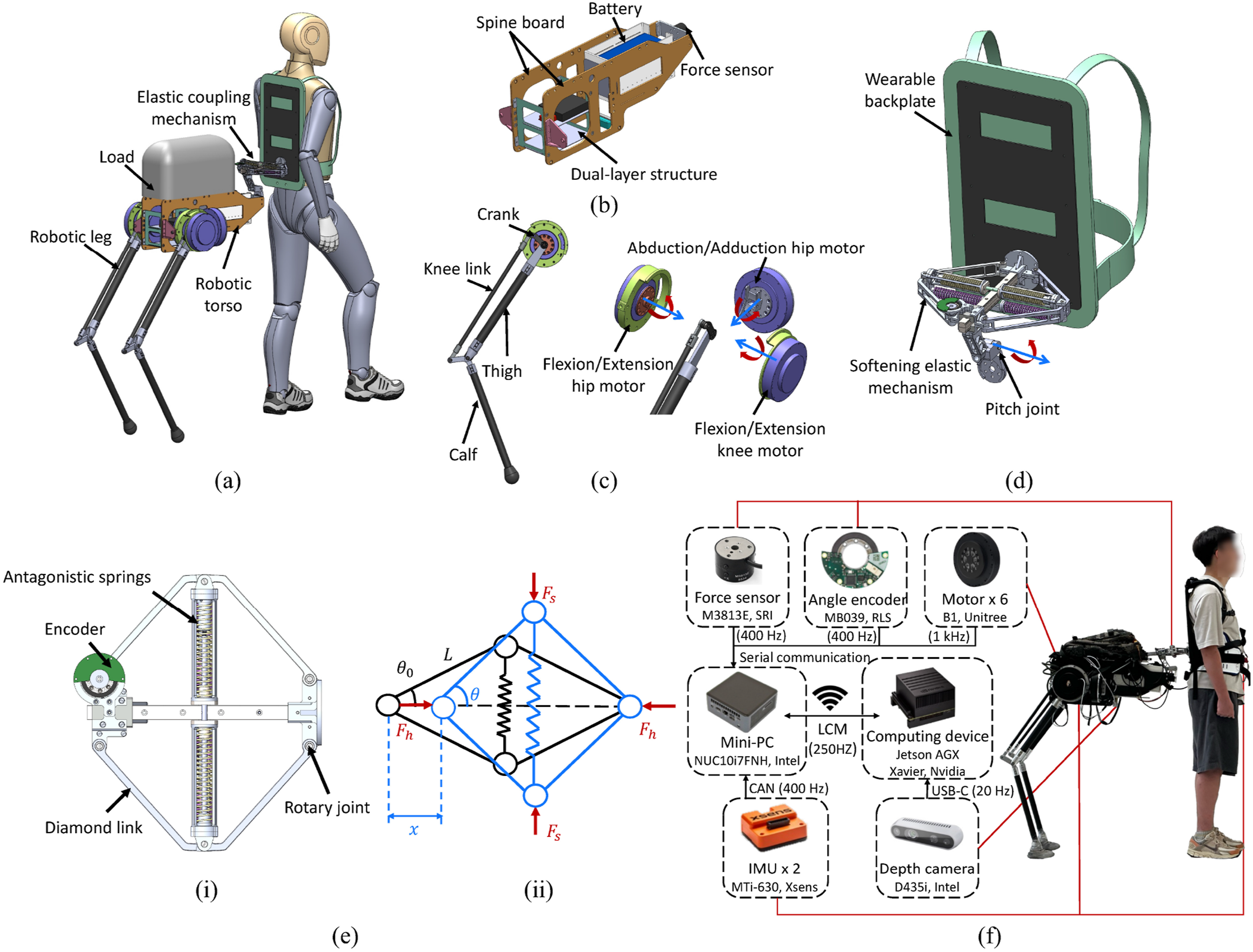
Ontology structure of the Centaur robot
The design goal of the Centaur ontology structure is to support the load and work in coordination with the human to enable omni-directional locomotion on various terrains in daily life. To ensure ergonomic compatibility and effective assistance, the structural design is informed by the anthropometric characteristics of typical adult users, with a target height range of 163–180 cm.
Robotic torso
The main function of the robotic torso is to secure the robotic legs and connect with the human, while accommodating electronic components, sensors, and payloads. As shown in Figure 1(b), the robotic torso is designed with a symmetrical arrangement of dual spine boards. These spine boards are made of carbon fiber to ensure both structural strength and lightness, and they can also be used to carry loads. The main torso structure is designed with a zoned, layered approach: the front section is designated for the battery, while the rear section is divided into dual layers for the electronic components. To maintain proportional harmony within the human-Centaur system, the torso dimensions are derived from biologically inspired ratios observed in natural quadrupeds. According to Leach and Cymbaluk (1986), the torso length, measured from the shoulder to the hip, accounts for approximately 77% of the shoulder height in horses. This biomimetic ratio is applied to the average CoM height of target human users (i.e., the approximate location of the human-Centaur coupling point). The CoM height is about 53% of human height, as reported by Neumann et al. (2017). The final outline dimensions of the robotic torso are determined as 630 mm × 140 mm × 240 mm (length × width × height), taking into account the space occupied by the wearable coupling mechanism.
Moreover, both the robotic legs and the payloads are mounted toward the rear of the torso, resulting in a posteriorly biased mass distribution. This rearward placement shifts the torso’s CoM backward, which increases the moment arm of the load force relative to the human-Centaur interface. Consequently, a greater portion of the balancing torque can be provided by the Centaur’s GRFs, reducing the support effort required from the human and facilitating cooperative load sharing. Concentrating the mass at the rear of the torso physically separates the robotic components from the human’s limbs, minimizing kinematic interference and reducing the risk of impeding natural joint motion during walking. This design strategy aligns with prior findings in Abeywardena et al. (2024), where posterior mass distribution is shown to improve stability and reduce the biomechanical load on the human.
Robotic leg
The robotic legs are designed for omni-directional locomotion and load-carriage capacities. To achieve omni-directional movement and balance control, the CoM of the Centaur robot must maintain six DoFs in both position and orientation. Therefore, each leg is equipped with three joints, providing the necessary flexibility and control to match these DoFs. Specifically, each robotic leg includes an abduction/adduction hip joint, a flexion/extension hip joint, and a flexion/extension knee joint. This configuration allows the Centaur robot to move in coordination with the human in a 3D Cartesian workspace while effectively maintaining its balance.
To reduce the rotational inertia at the knee joints and distal links of the legs, a parallelogram linkage structure is employed to drive the knee’s movement, as shown in Figure 1(c). The parallelogram linkage design can help reduce the rotational inertia and simplify dynamics modeling (Siciliano et al., 2008). Figure 1(c) illustrates that the motors of hip joints and knee joints are installed coaxially. Each robotic leg consists of a thigh, calf, crank, and knee link, with the knee link connecting the calf link and crank link. To ensure both strength and lightweight properties, the thigh, calf, and knee links are made from carbon fiber tubes, while the crank and the connections between the links are made from aluminum alloy.
To complement the design process and validate the structural configuration of the robotic leg, Appendix 2 presents the detailed kinematic modeling and workspace analysis, along with the design parameters and joint range specifications of the developed prototype.
Elastic coupling mechanism
Rigid coupling between the human and the Centaur robot may appear intuitive, but it introduces considerable mechanical impedance at the interface, making it difficult to achieve the desired horizontal interaction. Previous literature (Yu et al., 2015; Braun et al., 2019) underscores the importance of compliance in enhancing human-robot interaction performance. However, unlike conventional direct motor-driven interaction systems, the Centaur robot relies on leg-driven locomotion and exhibits significant under-actuation, resulting in poor control accuracy over its torso. Given the limited controllability and structural compactness requirements, the human-Centaur elastic coupling mechanism is required to adopt a specially designed nonlinear stiffness profile to achieve both high force resolution and a wide force output range within a constrained horizontal mechanical stroke.
A wearable elastic coupling mechanism is proposed and integrated into the human-Centaur system, as illustrated in Figure 1(d), which comprises three components: a wearable backplate, an elastic mechanism, and a pitch joint. The design of the elastic mechanism builds upon the mathematical modeling and parameter optimization presented in our previous work (Tu et al., 2024). One end of the elastic mechanism attaches to the human waist via the backplate, while the other end is attached to the front of the Centaur’s torso through a pitch joint.
This configuration enables compliant relative motion in the horizontal direction within the sagittal plane, facilitating horizontal interaction. The pitch joint further allows the robotic torso pitch motion to accommodate different terrains and different heights of the human. The remaining translational and rotational DoFs at the human-Centaur interface are structurally fixed by the backplate connection. Minor roll and yaw flexibilities are intentionally introduced through structural clearance to enhance comfort and adaptability while maintaining effective force transmission. This resulting natural haptic feedback helps the human perceive the motion state of the independent, heterogeneous Centaur robot and contributes to establishing confidence during locomotion (Guggenheim and Asada, 2020; Eden et al., 2022).
The elastic mechanism, shown in Figure 1(e) (i), consists of a diamond-shaped linkage with four equal-length links connected by rotary joints and vertically arranged antagonistic springs, which act as a tension spring generating elastic force at the vertex of the frame. To illustrate the mechanism’s working principle, Figure 1(e) (ii) presents its kinematic configuration. When compressed by a distance x relative to the initial state of the elastic mechanism, the equivalent tension spring exerts an inward tension F
s
, resulting in a horizontal interaction force F
h
. This force is governed by a nonlinear relationship, with its analytical form given as:
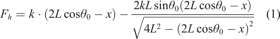
As revealed by the analytical model, the mechanism exhibits a novel softening nonlinear-stiffness profile, where the stiffness gradually decreases with increased compression and eventually approaches zero. The softening stiffness profile is characterized by high stiffness at low output forces and low stiffness at high output forces, enabling a broader output force range and higher force resolution within limited mechanical stroke. Such behavior is highly suitable for application in the human-Centaur system. Within the targeted interaction force range, the enhanced force resolution due to lower stiffness can compensate for the inherent control limitations. Simultaneously, the intrinsic compliance stabilizes interaction forces during unexpected events such as emergency stops or collisions, ensuring safe human-robot interactions.
Hardware configuration of human-Centaur system
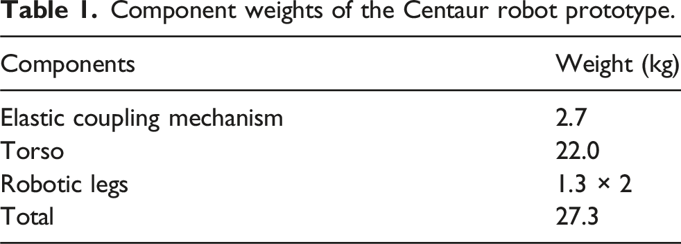
Component weights of the Centaur robot prototype.
The Centaur robot is equipped with a mini-PC (NUC10I7FNH, Intel, USA) running the Ubuntu OS for real-time control operations and an edge computing device (Jetson AGX Xavier, Nvidia, USA) that collects depth point cloud data and calculates terrain height information. Wireless data communication between the controller and the computing device is handled via LCM (Lightweight Communications and Marshalling). All electronic components are powered by two lithium batteries. A 12000 mAh 51.8 V LiPO battery is responsible for driving the motors, while another 5700 mAh 22.2 V LiPO battery powers the controller, computing device, and sensor components through voltage regulation.
Modeling
By incorporating the softening elastic mechanism into the human-Centaur system and precisely characterizing its force-displacement relationship, the human-Centaur interaction becomes more compliant and can be accurately represented. In this section, the interaction model between the Centaur robot and the human is developed. This compliance-based interaction model facilitates the decoupling of the human-Centaur system, enabling independent modeling of the Centaur robot dynamics. Subsequently, based on the decoupled dynamics, we can develop corresponding control strategies tailored to the Centaur robot.
Compliance-based interaction model
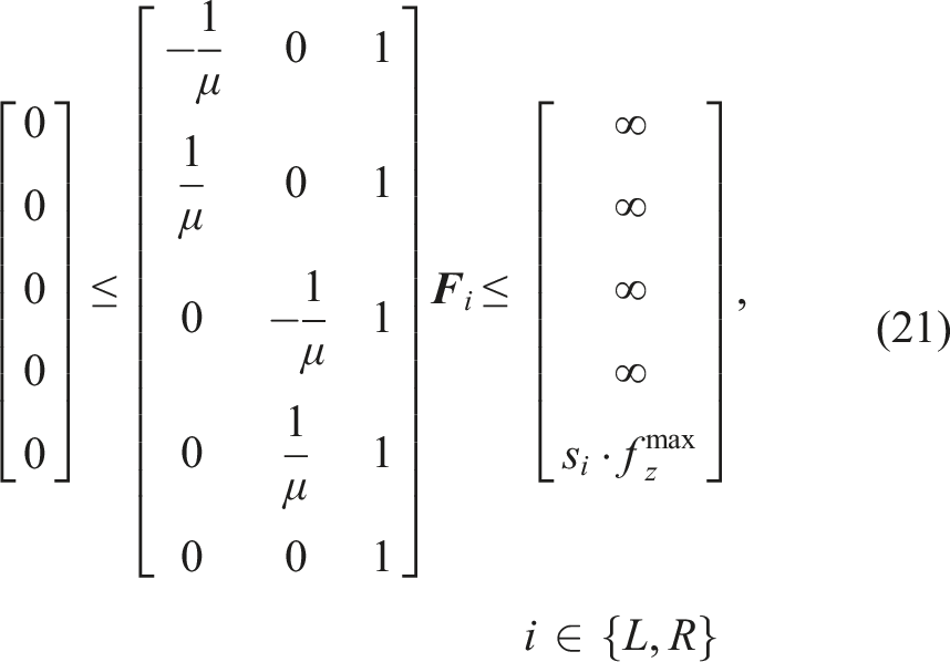
As illustrated in Figure 2, the interaction force Decoupling and modeling schematic of the human-Centaur system. The coordinate systems {W}, {C}, and {H} represent the world frame, the Centaur torso frame, and the human frame, respectively. The GRFs acting on the Centaur’s left and right feet are denoted as 
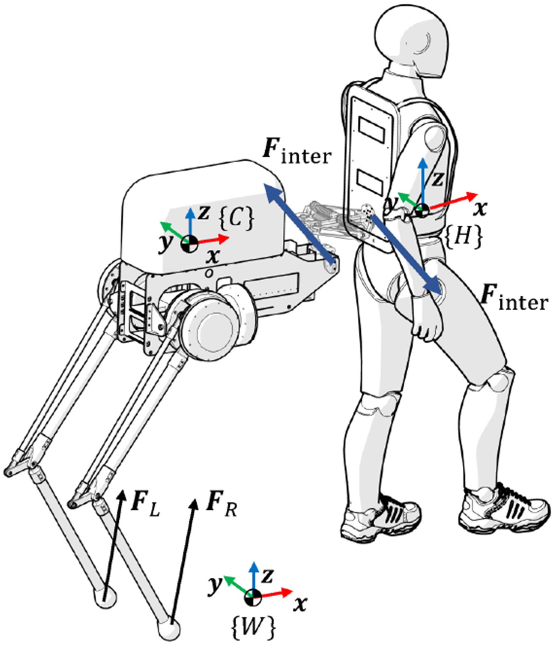
Decoupled dynamics of the Centaur robot
After establishing the compliance-based interaction model via the elastic coupling mechanism, the human-Centaur system can be decoupled for independent dynamic analysis. The Centaur robot can thus be regarded as a unique bipedal robot featuring two 3-DoF robotic legs and subjected to the interaction force 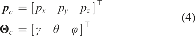
Single rigid body dynamics
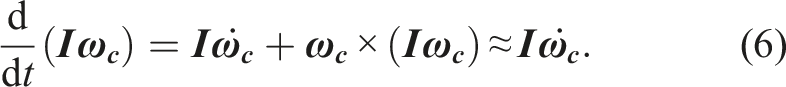
As shown in Table 1, the robotic torso, weighing 22.0 kg, constitutes the majority of the Centaur robot’s mass compared to the carbon fiber robotic legs, which weigh only 2.6 kg in total. Given this substantial mass discrepancy, the mass of the legs can be reasonably ignored, allowing the Centaur to be modeled as a single rigid body.
According to the SRBD, the dynamics of the decoupled Centaur robot can be expressed as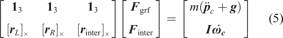
Multi-body dynamics
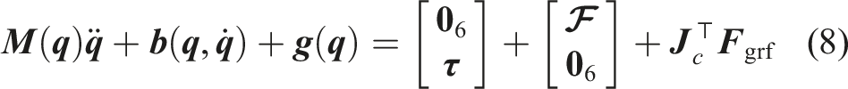
When considering the leg mass and rotational inertia, the Centaur robot can be modeled as a multi-body system. Compared to SRBD in Cartesian space, the generalized coordinates of the Centaur robot’s multi-body system with a floating-base can be expressed in the world frame as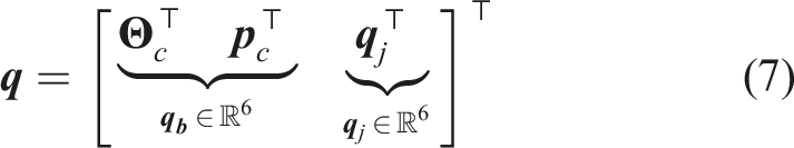
Control
Unlike conventional autonomous bipedal robots (Hubicki et al., 2016; Apgar et al., 2018), the Centaur robot possesses fewer control DoFs, and its torso mass distribution does not inherently ensure static stability. When carrying a load, the CoM of the Centaur robot often falls outside the leg support area. To maintain balance and control the horizontal interaction force, the Centaur robot must actively regulate the contact interactions between the feet and the ground under the dynamic support of the external interaction force.
In this section, the proposed loco-interaction control architecture is shown in Figure 3, which consists of three main components: collaborative motion planner, loco-interaction stance leg controller, and terrain-adaptive swing leg controller. The overall control framework runs at 250 Hz, with the loco-interaction MPC operating at a lower frequency of 50 Hz for multi-horizon optimization. Overview of the loco-interaction control architecture for the human-Centaur system. The overall control architecture begins with the collaborative motion planner, which determines the desired CoM trajectory 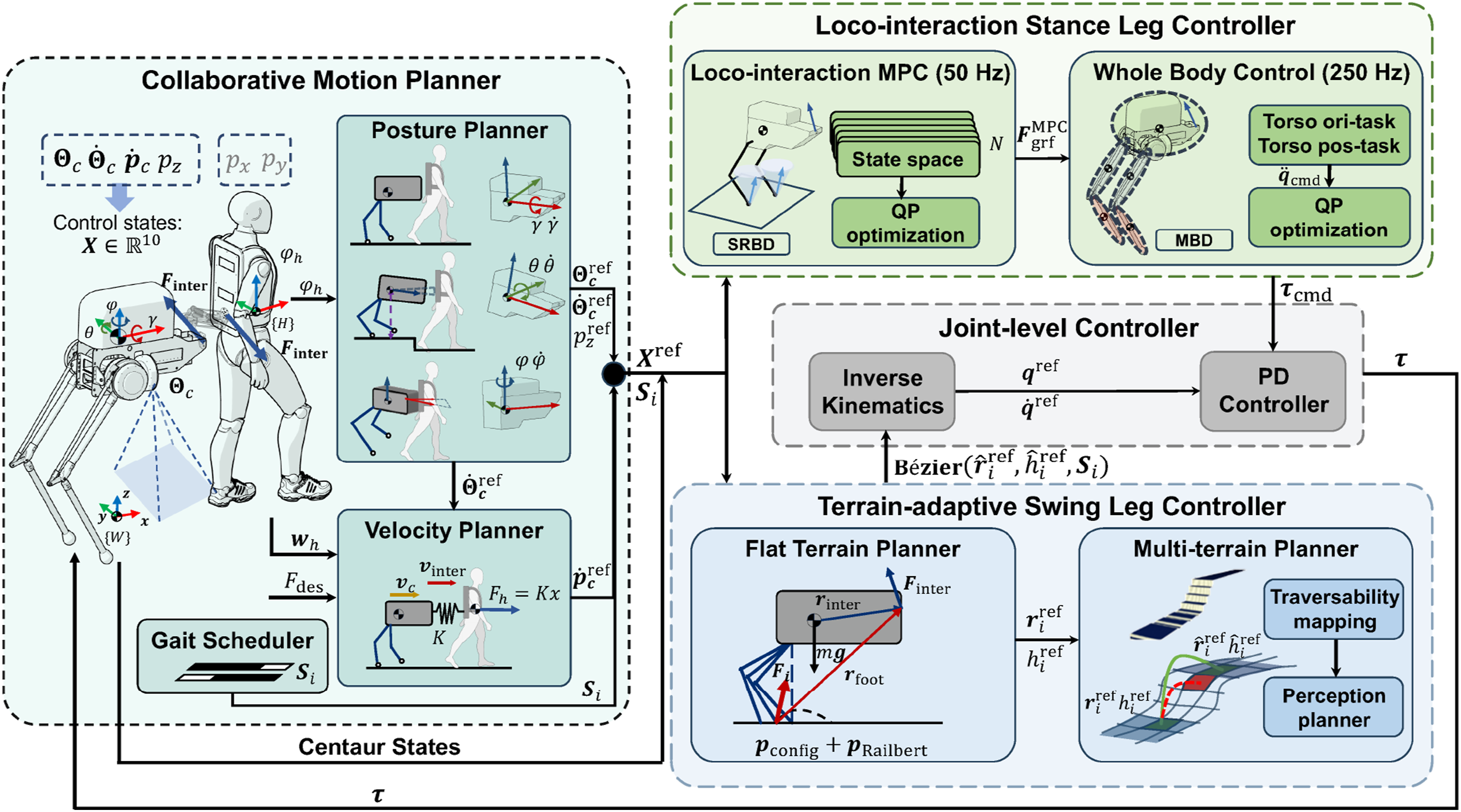
Collaborative motion planner
In the human-Centaur quadruped system, the human is responsible for high-level navigation and decision-making. The motion state and intent of the human determine the global motion of the system through walking direction and velocity. The Centaur robot, on the other hand, must coordinate with the human by actively maintaining its own posture balance, regulating the forward interaction force, and avoiding conflicts with human motion to minimize disturbances in other directions. Based on this division of roles, a collaborative motion planner is developed to generate real-time reference trajectories for the Centaur robot, utilizing the estimated human state and a task-defined desired interaction force.
Given the shared control nature of the human-Centaur system, explicit planning is only required for a subset of the Centaur’s CoM states that enable it to coordinate with the human and fulfill its assistive role. Specifically, the collaborative motion planner generates reference trajectories for a 10-dimensional state vector
The goal of the collaborative motion planner is to closely align the velocity of the Centaur’s interaction point relative to the human with the actuation direction of the elastic mechanism, thereby minimizing robot-induced disturbances to the human in directions other than the forward assistance. To achieve this, the planner first determines the desired torso posture, angular velocity, and height based on the current human walking state. Subsequently, a reference velocity at the interaction point is constructed by combining the desired motion along the elastic mechanism direction with the velocity induced by the human’s rotational movement. This interaction point velocity serves as the basis for computing the desired CoM linear velocity of the Centaur through rigid body kinematics. All reference trajectories are expressed in the world frame to maintain consistency throughout the planning and control pipeline. Accordingly, the collaborative motion planner is composed of three key modules: a torso posture planner, a torso velocity planner, and a gait scheduler for step timing and sequencing.
Torso posture planner
The torso posture planner primarily determines the reference trajectories for the Euler angles and corresponding angular velocities of the Centaur robot based on the human walking posture. Specifically, to ensure that the Centaur’s torso does not tip over, the reference trajectory for the roll angle of the Centaur’s torso γ should be zero, as the roll is independent of the human’s posture. Additionally, to ensure that the Centaur robot can turn in unison with the human, the yaw angle of the Centaur φ should align with the yaw angle of the human φ h .
When the human-Centaur system encounters uneven terrain, the Centaur needs to adjust its pitch angle to accommodate the height difference relative to the human. Additionally, since the front end of the Centaur’s torso is mechanically coupled to the human, any change in torso pitch angle θ simultaneously alters the vertical position p
z
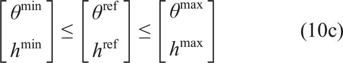
. Hence, it is necessary to simultaneously plan the pitch angle and torso height to adapt to the height variations. An optimization problem is formulated to determine the reference values 


The torso posture planner first generates the target trajectories for the Euler angles 
Torso velocity planner
As part of the collaborative motion planner, the torso velocity planner computes the desired CoM linear velocity that enables the Centaur to realize the intended interaction behavior. Specifically, a target velocity at the torso’s interaction point relative to the human
To generate the reference relative velocity, a feedback-based velocity generator is proposed, which relies on the compression state of the elastic mechanism to regulate the horizontal human-Centaur interaction force, as illustrated in Figure 4(a). Based on equation (1), the desired compression state xdes of the elastic mechanism is derived using the inverse interaction model from the desired interaction force Fdes. Subsequently, the compression error x
e
is processed by a PID controller to generate the target relative velocity Schematic diagram of the torso velocity planner. (a) Block diagram of the generation of the desired relative velocity at the interaction point 
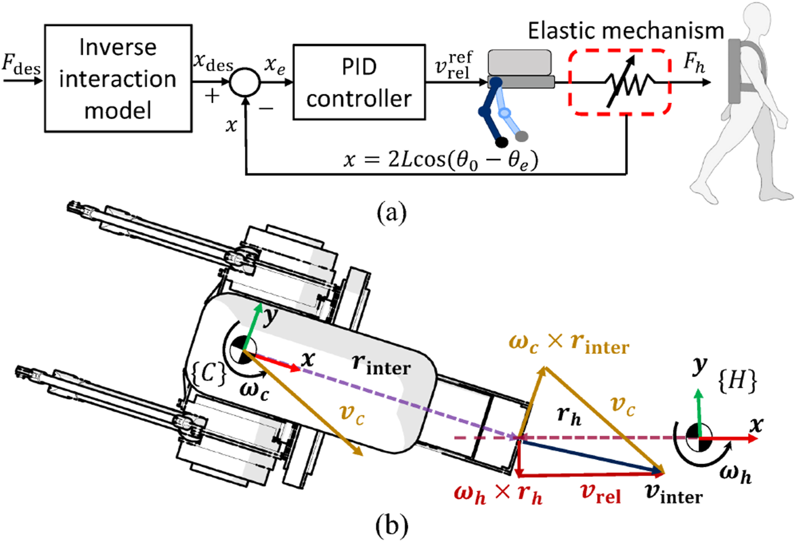
As illustrated in Figure 4(b), the interaction point velocity can also be expressed from the Centaur’s side in terms of the CoM linear velocity 

Gait scheduler
The gait scheduler is designed to organize the Centaur’s gait behaviors, determining the swing and support phases for each leg. Diverging from previous studies (Hao et al., 2020; Khazoom et al., 2020), we do not synchronize the Centaur’s gait patterns with human gait due to the differences in leg mechanical structures and actuation. The Centaur robot generally necessitates more frequent gait transitions compared to humans to maintain dynamic balance. By adopting independent gait patterns, the Centaur robot can more effectively plan and control its balance and enhance terrain adaptability.
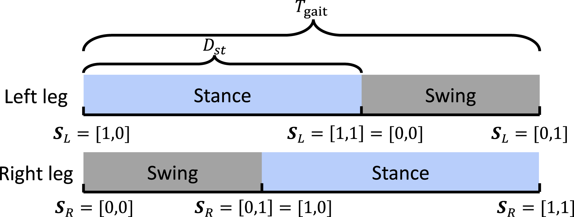
The gait of legged robots is usually periodic, so the gait cycle time Tgait and the proportion of stance period in the gait cycle D
st
can be used to parameterize the gait pattern of the Centaur robot, as shown in Figure 5. In this work, both Tgait and D
st
are predefined as constant parameters based on empirical tuning to ensure stable locomotion. The gait vector Gait diagram for bipedal locomotion of the Centaur robot. The values of the gait vectors 
Loco-interaction stance leg controller
Loco-interaction MPC
Based on the proposed collaborative motion planner, the CoM reference trajectories and gait pattern of the Centaur robot are planned to achieve torso balance and interaction force control. To enable the Centaur robot to follow the planned CoM trajectory and achieve the desired walking and interaction behaviors, a loco-interaction MPC framework is proposed based on the SRBD model in equation (5). By utilizing the convex loco-interaction MPC (50 Hz), the desired GRFs are regulated to maintain the Centaur robot’s desired posture, height, and velocity in versatile locomotion.
A linear state-space model of the Centaur robot, based on the determined control state 
The discrete form of the state-space equation (16) at each MPC time step i is shown as
The discrete state-space model formulates a linear MPC problem with a finite horizon length N written in the form as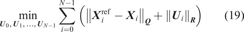


When the swing leg makes contact with the ground, a significant impact occurs between the foot and the ground. This impact directly affects the torso’s posture and causes changes in its velocity, posing a challenge to the Centaur’s balance and horizontal interaction force control. To address this issue, we aim to achieve soft landing in the early stage of the stance phase beginning from the touchdown, introducing a time-varying maximum contact force 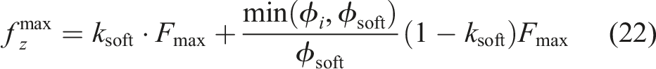
Moreover, an adaptive velocity weight is also introduced to help the Centaur better balance torso posture and interaction force control. Considering that stable torso posture is fundamental to interaction force control, when the force control error is large, the interaction force on the Centaur is relatively small. In this scenario, we prioritize the control of the Centaur’s posture and height by reducing the horizontal velocity weight. Conversely, as the interaction force error gradually decreases, the Centaur robot requires larger horizontal GRFs to counteract the disturbance of the horizontal interaction force. Therefore, the velocity weight will adaptively increase to help generate larger horizontal GRFs, ensuring the stability of interaction force control. The adaptive equation for the velocity weight is denoted as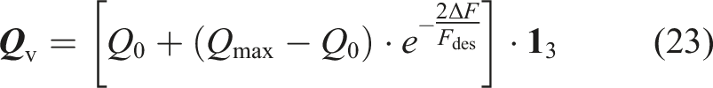
Whole body control
The proposed loco-interaction MPC, based on the decoupled SRBD and interaction force information, solves for the GRFs to follow the desired CoM trajectory. However, its relatively low update frequency (50 Hz) limits the responsiveness to rapid fluctuations in human motion and interaction dynamics. These high-frequency disturbances are difficult to model and compensate within the MPC loop, leading to degraded tracking performance. To address this limitation, a high-frequency WBC framework (250 Hz) is integrated into the loco-interaction architecture. Taking the GRFs obtained by the loco-interaction MPC
For the Centaur robot, the WBC framework organizes control objectives into two tasks from high to low priority: CoM orientation control task 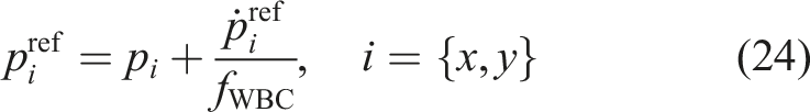
Based on the CoM reference trajectory generated in collaborative motion planner and equation (24), the task-space acceleration commands of the CoM position and orientation are computed by a PD controller,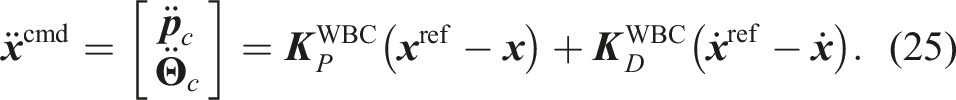
The task acceleration commands
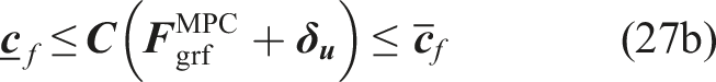
To ensure consistency between the joint acceleration commands from WBC and the GRFs computed by the loco-interaction MPC, a quadratic programming (QP) problem is formulated. The QP minimizes the relaxation variables 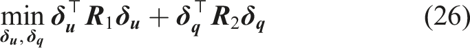
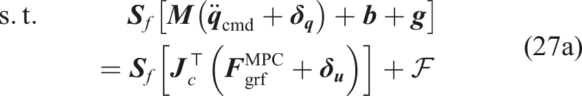
Finally, the joint torque commands 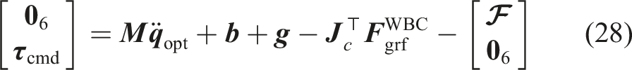
Terrain-adaptive swing leg controller
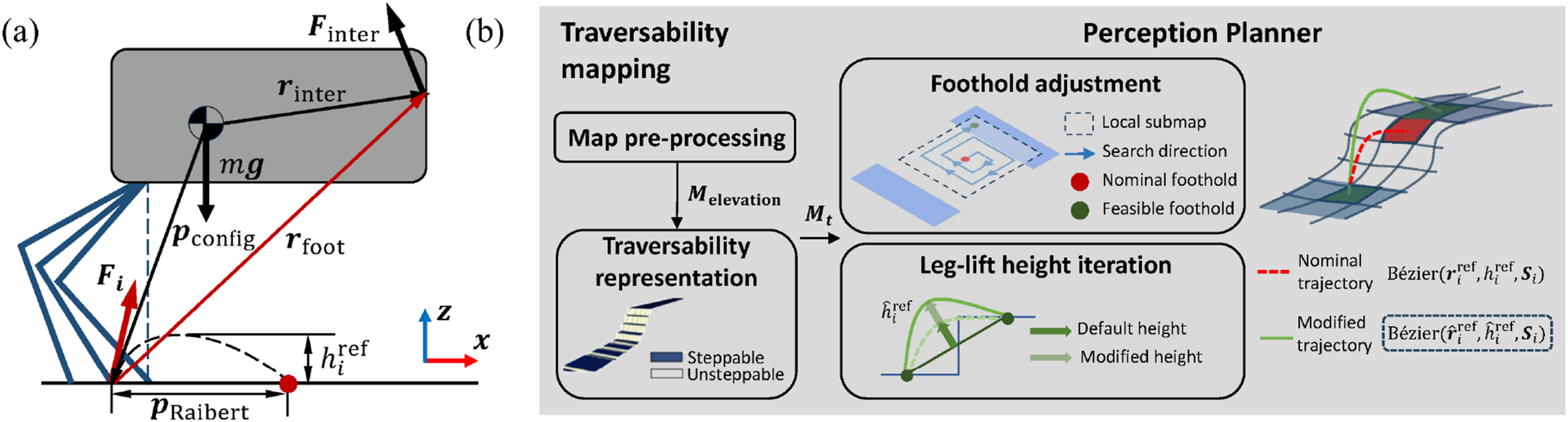
The proposed terrain-adaptive swing leg controller is pivotal in enabling the Centaur robot to maintain coordinated posture and regulate the interaction force, while also improving its capacity to navigate diverse terrains. This controller operates by planning both the foothold and swing height. The proposed terrain-adaptive swing leg controller is divided into two main components: the flat terrain planner and the multi-terrain planner. The flat terrain planner generates the nominal foothold and default leg lift-height based on the Centaur’s state, desired interaction force and dynamic characteristics. The multi-terrain planner leverages visual perception information to refine the nominal planned foothold in flat terrain, avoiding terrain edges or gaps and ensuring smooth adaptation to terrain transitions. Additionally, it modifies the leg’s lift-height to generate a collision-free and terrain-appropriate swing trajectory.
Flat terrain planner
The nominal foothold of the Centaur robot on flat terrain is calculated by the following equation with terms:
Typically, the default foothold for legged robots is the ground projection of the foot directly beneath the hip joint (Di Carlo et al., 2018; Kim et al., 2019), with the final placement being planned based on this position. The first term in the proposed foothold equation, Schematic diagram of the terrain-adaptive swing leg controller. (a) Schematic illustration of the flat terrain planner. The blue solid lines represent different foot configurations of the Centaur robot. The vector 
From the above equation, it can be observed that when the Centaur is in a steady-state motion, that is, 
Then the foot configuration 
The second term 
A default leg-lift height
Multi-terrain planner
The flat terrain planner is designed to enable the Centaur robot to maintain balance and track the desired CoM trajectory on flat terrain. However, it does not account for the constraints imposed by terrain edges or transitions on the swing trajectory. When the human-Centaur system navigates uneven or varying terrains, it is essential to integrate terrain information to adjust the foothold and avoid unintended missteps or collisions.
The multi-terrain planner refines the nominal foothold and default leg-lift height using terrain-aware information. Terrain information is represented as an elevation map (Miki et al., 2022b), which is further processed into a traversability map
First, the raw elevation map of the terrain in the Centaur robot’s local vicinity is constructed by combining odometry data, the Centaur robot’s posture, and depth point cloud information. In map pre-processing, to generate the elevation map
To evaluate the traversability of grid cells in the elevation map, three key metrics are iteratively assessed: (a) terrain edges, (b) terrain roughness, and (c) terrain slope (Kaehler and Bradski, 2016). Terrain edges are detected using the Sobel gradient operator, which highlights sharp transitions, such as the edges of stairs or obstacles. Terrain roughness quantifies surface irregularities, particularly relevant for gravelly or rocky surfaces, and is determined by calculating the local variance of grid cell heights. Terrain slope measures the inclination of the terrain and is computed using singular value decomposition (SVD) over a local neighborhood of the elevation map. For each grid cell, an objective function value is calculated as a weighted sum of these metrics, resulting in the generation of a traversability map. In the traversability map, a value closer to 0 indicates a safer location for the Centaur robot to place its foot, whereas a value approaching 1 signifies a higher likelihood of risk, such as terrain edges or obstacles. To enhance decision-making, an additional layer is added to the traversability map, where the traversability values are binarized into 0 (steppable) or 1 (unsteppable), corresponding to the same grid cells in the original map. The binary traversability map
After generating the traversability map, inspired by foothold optimization methods in legged robotics (Jenelten et al., 2020; Grandia et al., 2023), the proposed perception planner refines the nominal foothold and default leg-lift height using the elevation and traversability information in
Experiment evaluation
Control parameters of the Centaur robot.
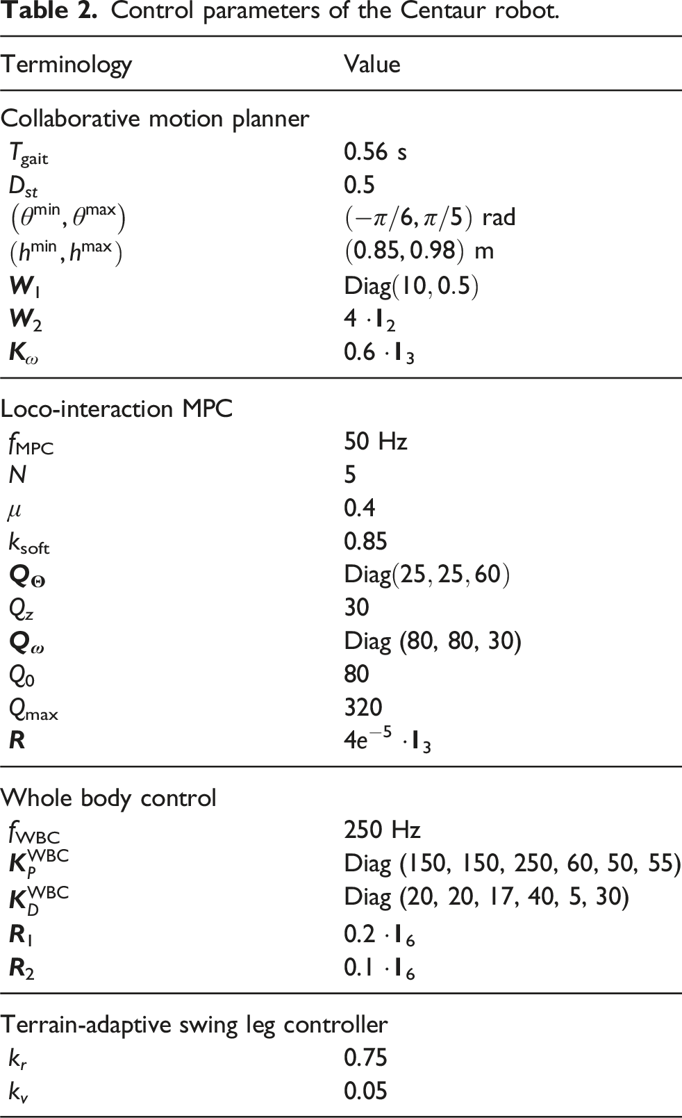
A total of 10 healthy subjects (5 male, 5 female; age: 22 ± 3 years; weight: 61.3 ± 11.0 kg; height: 170.0 ± 4.3 cm; mean and standard deviation) were recruited to participate in the experiments (Table 6). The experiment protocol received ethical approval from the Medical Ethics Committee at Southern University of Science and Technology (approval No. 20220031) on February 25, 2022. All participants provided written informed consent prior to enrollment in the experiments.
Wearing test
Experimental setup
The wearing test was conducted to evaluate the ease of donning and doffing the Centaur robot, as well as its suitability for all of the ten participants. Before the test, a verbal briefing was provided to each participant, outlining the wearing procedure and steps.
The donning and doffing process was assisted by a trained operator, who started the control program and adjusted the initial height of the Centaur robot for each participant. The total time required for each participant, including setup, adjustment, and the full donning or doffing process, was recorded. To examine whether participant height influenced donning or doffing time, Pearson correlation analyses were performed between participant height and each of the recorded times.
Results
All participants were able to quickly don and doff the Centaur robot. The adjustable torso height of the Centaur robot successfully accommodated all participants (163 –178 cm). The test results show that with the assistance of one person, the average donning time, including the initial height adjustment of the Centaur robot, was 50.3 ± 8.3 s. The doffing time of the Centaur robot was 25.2 ± 3.0 s. Specific statistics on donning and doffing times are provided in Table 6 in Appendix 4. No significant correlation was found between participant height and donning time (R = 0.431, P = 0.214), nor with doffing time (R = 0.161, P = 0.656).
Level ground experiment
Experiment setup
The level-ground walking experiment consisted of two parts: (1) a multi-subject triangular walking trial and (2) maneuverability tests involving slalom walking and turning in narrow spaces. In the first part, all ten participants were instructed to walk a triangular path of approximately 100 m around a flower bed in an outdoor setting. Each participant walked at a self-selected, comfortable pace. To evaluate the degree of interaction disturbance during walking, mean absolute errors (MAEs) of the lateral interaction force F y and the interaction torques (M x , M y , M z ) were calculated. Posture tracking performance of the Centaur robot was quantified using root mean square (RMS) errors of torso orientation (roll, pitch, yaw). Group-level performance was analyzed by computing the average errors and standard deviations across all participants. The generalization and consistency of the control strategy were evaluated by performing Pearson correlation analyses between participant height and walking performance metrics.
To evaluate the flexibility and coordination of the human-Centaur system during collaborative walking, one participant performed the maneuverability tests. In the slalom walking task, five cones were placed at 1 m intervals along a straight line, with a lateral clearance of 2.4 m. The participant was instructed to walk in a zigzag pattern around the cones to the end and then return by weaving around the opposite sides, forming a figure-eight trajectory. In the turning task, the participant executed a 540-degree turn within a confined space 1.2 m wide. These tasks were designed to demonstrate the system’s ability to handle directional changes and navigate narrow spaces with smooth human-robot coordination.
Results
The left panel of Figure 7(a) presents an overhead view of the outdoor triangular walking experimental site, along with the estimated walking trajectories of the participants. The right figure shows snapshots of different participants during collaborative walking (see also Extension 1). For walking trials with 10 participants, the RMS error in tracking the human yaw was 0.0856 ± 0.0353 rad (mean ± standard error), while the RMS errors in tracking the desired roll and pitch were 0.0585 ± 0.0054 rad and 0.0234 ± 0.0053 rad, respectively (with the desired values being 0 during level-ground walking). The average walking velocity of all the participants ranged from 0.87 m/s to 1.20 m/s, closely matching normal human walking velocity (Neumann et al., 2017). Pearson correlation analysis revealed no significant correlation between participant height and the Centaur’s torso posture or average walking speed (all P > 0.05). These results demonstrate that the Centaur robot can accurately track and adapt to the human’s walking direction and speed while maintaining posture balance, regardless of individual anthropometric differences. Level ground experiment. (a)–(d) Multi-subject triangular walking experiment. (a) Left: Top view of the experimental site with estimated Centaur trajectories from 10 trials. Right: Snapshots of different participants walking with the Centaur robot; numbers correspond to positions marked on the left. (b) Mean absolute errors (MAEs) of the lateral interaction force F
y
and interaction torques (M
x
, M
y
, M
z
) during walking. The bars represent the average MAEs across participants, with error bars representing standard deviations. (c) The measured and desired torso posture of the Centaur robot during walking with subject 2. (d) Commanded and actual motor torques for the abduction/adduction, hip, and knee motors of both robotic legs over 4-s segment (subject 2). (e)–(f) Maneuverability walking test. (e) Slalom walking. Left: Overlaid snapshots show the human-Centaur system weaving around cones. Right: Estimated figure-eight trajectory of the Centaur; yellow triangles indicate cone positions, and red arrows mark walking directions corresponding to the three overlaid positions. (f) Turning in a narrow space. Left: The participant performs a 540° turn with the Centaur robot. Right: Estimated trajectory within a 1.2 m-wide corridor; the red circular path corresponds to the motion on the left, and red arrows indicate entry and exit directions.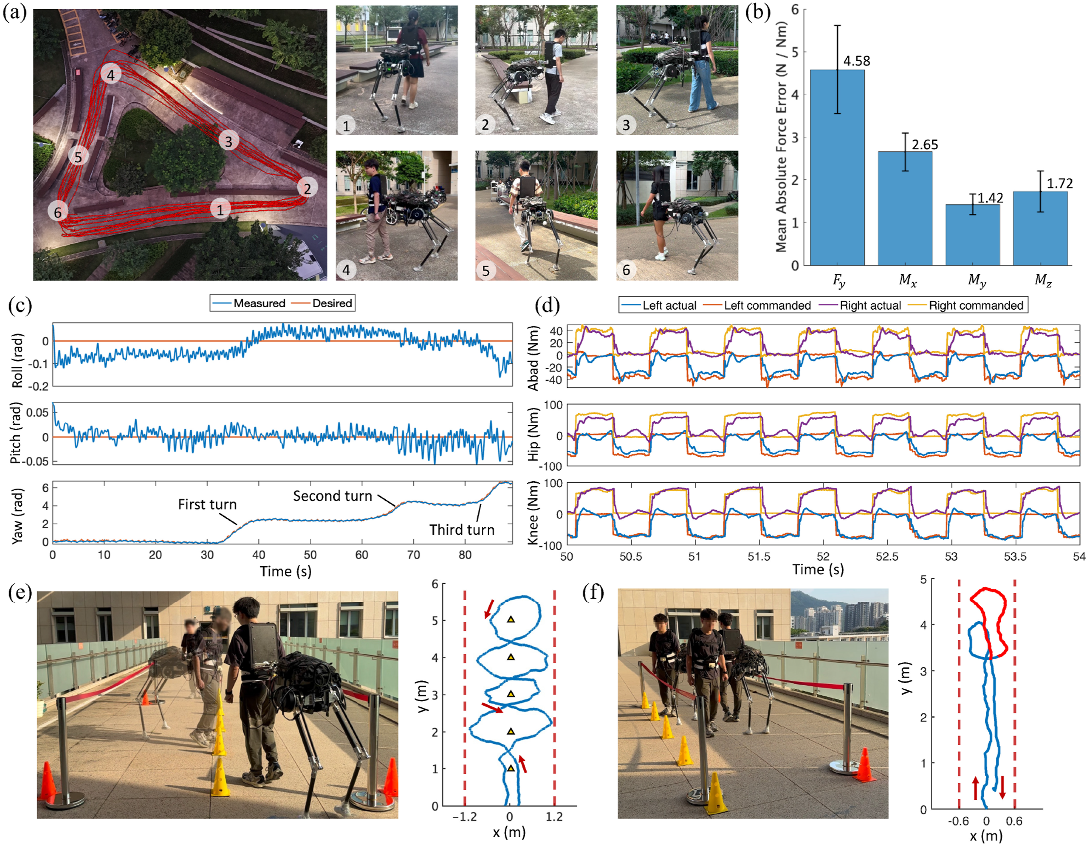
The MAE of the lateral human-Centaur interaction force was 4.58 ± 1.03 N, while the corresponding MAEs for interaction torques in roll, pitch, and yaw directions were 2.65 ± 0.45 Nm, 1.42 ± 0.24 Nm, and 1.72 ± 0.48 Nm, respectively. The low interaction forces and torques observed in the non-sagittal plane suggest minimal disturbance to natural gait, indirectly validating the effectiveness of the proposed collaborative motion planner. Interaction forces and torques of this magnitude are generally considered insufficient to impair human walking stability (Sterke et al., 2024), a point further corroborated by findings from the load-carriage experiments presented later.
Figure 7(c) presents time-series data of the Centaur robot’s torso posture during collaborative walking. The roll and pitch angles remained close to the desired zero reference on level ground, while the yaw angle followed the human’s walking direction through straight paths and three turns exceeding 90°. Notably, the roll angle exhibited a relatively fixed offset from zero in certain segments, potentially reflecting residual effects of terrain unevenness not fully compensated by the control strategy. Figure 7(d) shows the commanded and actual joint torques of the abduction/adduction, hip, and knee joints over several gait cycles. The close agreement between commanded and measured torques confirms accurate joint-level torque tracking and effective execution of coordinated locomotion control.
As shown in Figures 7(e) and (f), the human-Centaur system successfully completed continuous figure-eight walking between cones spaced only 1 m apart and executed multiple tight turns within a 1.2 m-wide space, roughly matching the system’s overall length (see Extension 1). These results demonstrate its high agility and coordination under tight spatial constraints, with turning radii substantially smaller than the overall system length. This performance reflects seamless physical and behavioral integration enabled by the collaborative control strategy. Notably, this coordination emerged without explicit commands, highlighting the intuitiveness and effectiveness of the human-Centaur shared-control architecture, in which the human naturally handles navigation while the Centaur robot provides physical assistance, enabling agile locomotion in confined environments.
Multi-terrain experiment
Experiment setup
To evaluate the locomotion performance of the human-Centaur system in multi-terrain and everyday outdoor scenarios, a series of multi-terrain walking experiments were conducted. The evaluation began with tests on standard terrains, including four distinct conditions: stair ascent (SA), stair descent (SD), ramp ascent (RA), and ramp descent (RD), to quantitatively assess the Centaur robot’s ability to traverse different terrains. Finally, comprehensive experiments were performed in everyday outdoor environments to further validate the effectiveness of the human-Centaur system in real-world scenarios, as well as the proposed modeling and control methods.
The stair-climbing experiment was conducted outdoors on a two-step staircase with dimensions of 30 cm × 12 cm (width × height). The participant first ascended the staircase with the Centaur robot to reach the level ground (LG), then turned around and descended the staircase to return to the initial height. To ensure safety, a supervisor accompanied the participant during the experiment but did not provide any physical assistance. The ramp-walking experiment was performed on a 6° incline, where the participant walked uphill from LG to the top of the ramp, turned around, and descended back to LG.
Results
Figure 8(a) shows snapshots of the Centaur robot during the SA and SD process. As the participant stepped onto the staircase, the Centaur robot adjusted its pitch angle to accommodate human-Centaur height discrepancy introduced by the stairs. Figure 8(c) illustrates the Centaur robot’s posture curves during transitions across the experiment, demonstrating effective planning and control of roll, pitch, and yaw angles around their desired values. During SA, the desired pitch angle transitions to a negative value, elevating the Centaur’s torso to align with the human’s upward movement. Conversely, during SD, the desired pitch angle shifts to a positive value, tilting the torso downward to follow the human’s descent. The RMS errors for roll, pitch, and yaw during the experiment were measured as 0.0671 rad, 0.0433 rad, and 0.0760 rad, respectively. Stair ascent and descent experiment. (a) Snapshots of the human-Centaur system during SA and SD. The first four snapshots depict the SA process, and the last four correspond to SD. (b) The visualization diagram of the Centaur robot and terrain during SA and SD process. The reconstructed traversability map highlights steppable areas in blue and unsteppable areas in white. Nominal foot trajectories, planned by the flat terrain planner, are shown as red lines, while actual feasible foothold and corresponding foot trajectories based on visual information are indicated by green dots and lines. The Centaur robot during the SA and SD processes is visualized in the diagram, corresponding to the snapshot labels in (a). (c) The posture of the Centaur robot during the experiment. Different terrains are labeled in the diagram, with shaded regions highlighting the SA and SD periods.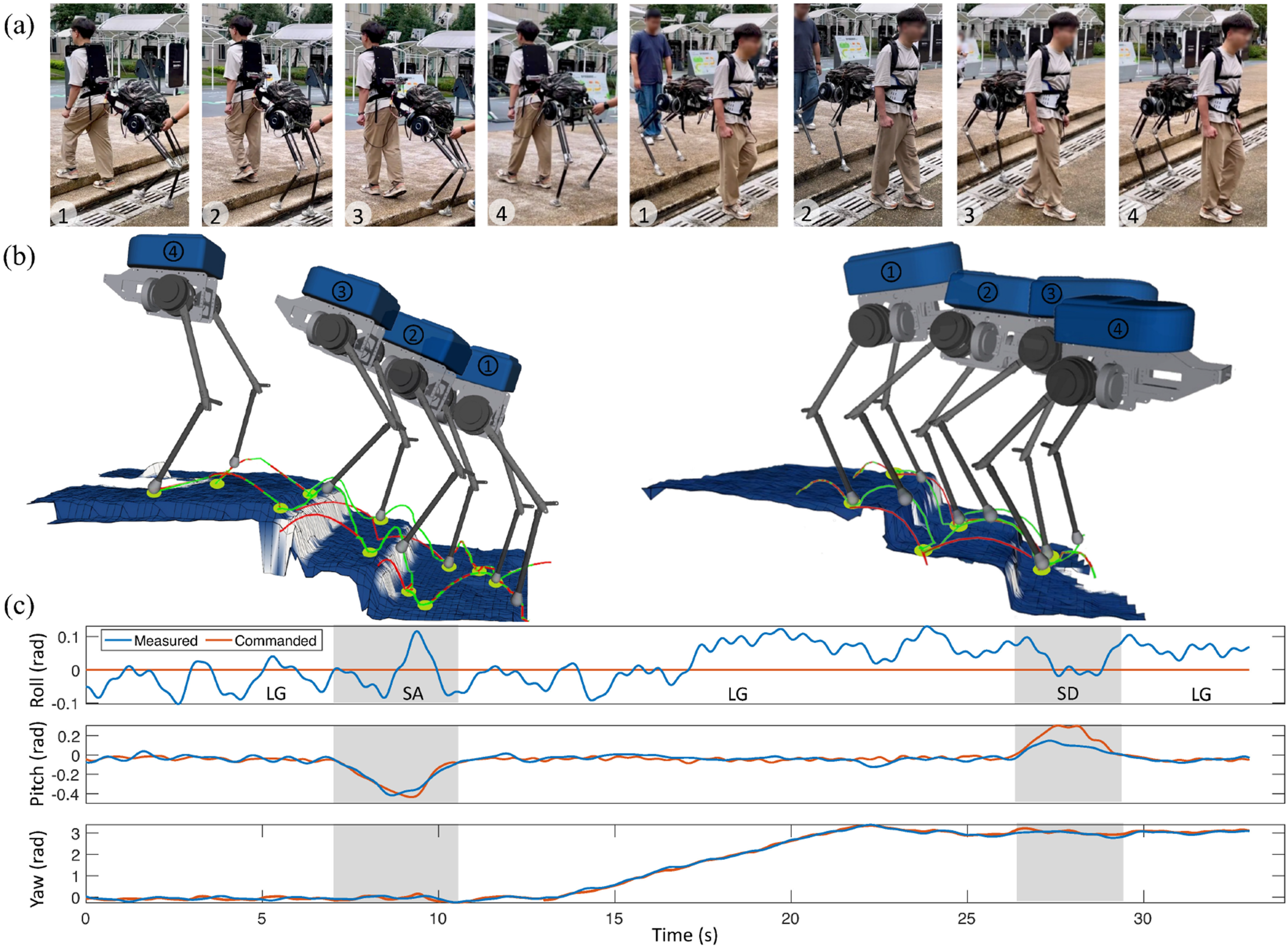
In addition to the torso posture adjustments generated by the collaborative motion planner, the Centaur robot utilized terrain information to plan feasible footholds, ensuring successful traversal of the staircase. Figure 8(b) illustrates the impact of the multi-terrain planner in adapting to varying terrains. The reconstructed terrain map beneath the Centaur robot vividly displays height variations and the distribution of steppable areas. A comparison of the nominal foot trajectories with the visually adjusted foot trajectories reveals how the planner adapts to ensure safe and effective locomotion across challenging terrains. When no terrain transitions or unsteppable regions are detected, such as before stepping onto the staircase or after returning to LG, the nominal and adjusted foot trajectories align closely. However, during the transition from LG to RA, significant adjustments are introduced. To avoid the staircase edges, which are considered unsteppable, the planner repositions the foothold to flat and steppable regions on the stairs. At the same time, the leg-lift height is increased to ensure a collision-free swing trajectory, facilitating smooth and reliable stair traversal. Similarly, during SD, although most of the entire stair surface is identified as a steppable area, the foothold and leg-lift height initially generated for flat terrain are adjusted to account for the height variation of the stairs. These adaptions ensure the Centaur robot’s stability and the correctness of its gait pattern, as shown in the right plot of Figure 8(b).
Figure 9(a) presents snapshots of the participant during the transitions from LG to RA and from RA to RD, corresponding to the Centaur model visualized in Figure 9(b). Similar to the stair-climbing experiments, the Centaur robot dynamically adjusted its torso pitch to accommodate changes in terrain. During ramp walking, the RMS tracking errors for roll, pitch, and yaw were 0.0584 rad, 0.0322 rad, and 0.0679 rad, respectively. From the swing trajectories in Figure 9(b), it is observed that during ramp walking, the nominal swing trajectory matches the actual trajectory, with notable differences only at the terrain transition steps. This consistency arises because a ramp can be effectively treated as an inclined flat surface. As a result, when the human-Centaur system walks along the ramp, the footholds generated by the flat terrain planner naturally conform to the ramp’s surface, eliminating the need for adjustments. However, at terrain transitions, the nominal footholds generated by the flat terrain planner may fail to adapt to the new terrain surface. In such cases, visual information is utilized to adjust the foothold positions to align with the actual terrain surface. Ramp ascent and descent experiment. (a) Snapshots of the human-Centaur system during RA and RD. (b) The visualization diagram of the Centaur robot and terrain during RA and RD process. Both the nominal and the visually adjusted actual foot trajectories of the left robotic leg are overlaid on the terrain map. The red solid lines represent nominal trajectories planned without incorporating visual information, while the green dots and solid lines denote the actual feasible foothold and foot trajectories adjusted based on visual information.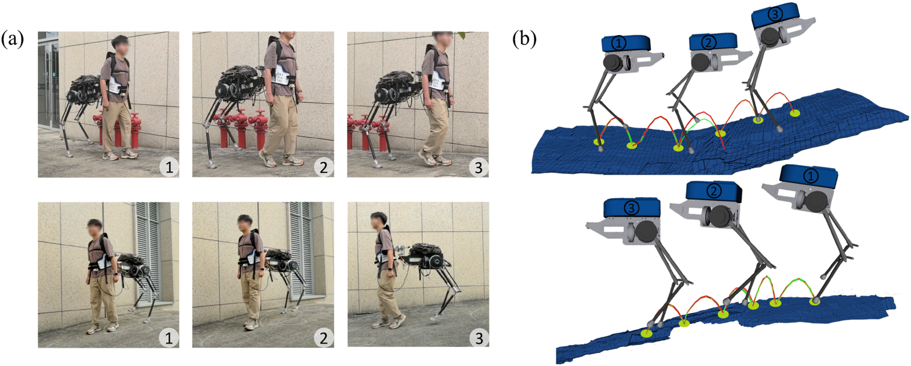
To further validate the walking capabilities of the human-Centaur system across diverse real-world outdoor terrains, a series of outdoor walking experiments were conducted on the campus. Figure 10 presents snapshots showcasing the human-Centaur system walking collaboratively across various outdoor terrains. These scenarios highlight the Centaur robot’s ability to adapt to diverse terrain types while maintaining stability and coordination with the human. The related multi-terrain walking experiment video of the Centaur robot is provided in Extension 2. Human-Centaur system navigating various everyday outdoor environments, including (a) grass fields, (b) brick-paved uphill ramps, (c) gravel paths, (d) mixed terrain of steps and grass fields, (e) concrete uphill ramps, and (f) dirt downhill ramps.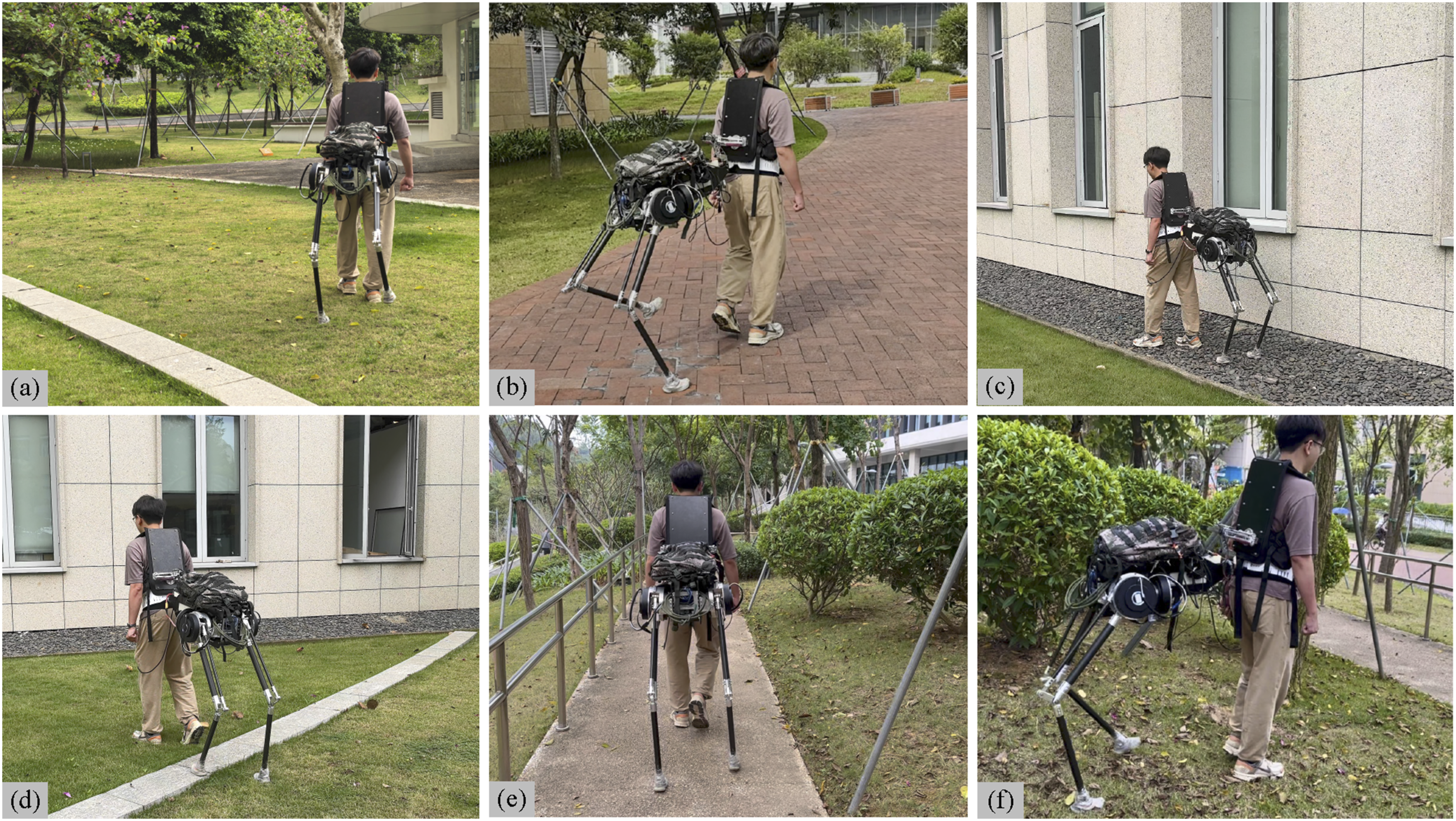
Interaction force control experiment
Experiment setup
To demonstrate the unique horizontal forward force assistance capability of the Centaur robot, interaction force control experiments were conducted under three different conditions: softening elastic coupling with the proposed loco-interaction controller (E-LIC), softening elastic coupling with static reduced-order controller (E-SRC), and rigid coupling with static reduced-order controller (R-SRC). The static reduced-order MPC controller proposed in our prior work (Yan et al., 2024) was deployed in the last two conditions for comparison. The controller assumes a fixed human-Centaur interaction force from the human and solves for GRFs accordingly, without considering dynamic interaction effects. The static interaction force 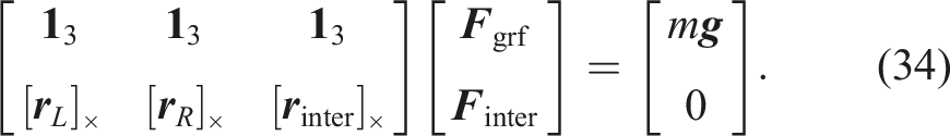
Moreover, the control state is defined as
Four participants (2 male, 2 female, 163–174 cm, 55–73 kg) were recruited to perform repeated experiments. To ensure consistent gait conditions, all experiments were conducted on a treadmill. The treadmill speeds were set to 0 m/s, 0.4 m/s, 0.7 m/s, and 1.0 m/s, with each speed interval lasting 15 s. For each interval, the treadmill uniformly accelerated to the next target speed over the first 4 s and then maintained a constant speed. The treadmill finally decelerated from 1.0 m/s to 0 m/s at a rate of −0.1 m/s2. This protocol provided a controlled and repeatable walking environment, enabling fair and quantitative comparisons across different coupling and control strategies.
In the E-LIC condition, the desired horizontal interaction force between the human and the Centaur robot was set to 40.0 N. The comparison across all conditions highlights the advantages of the softening elastic coupling and loco-interaction controller in achieving compliant and controllable human-Centaur interaction. Paired t tests were used for statistical comparisons, with Cohen’s d z as the effect size. When the normality of paired differences was violated, the Wilcoxon signed-rank test was applied, and effect sizes were reported as rank-biserial correlation r. A significance level of P < 0.05 was used for all tests.
Results
Under all experimental conditions, the human-Centaur system successfully followed the treadmill’s varying speed profiles. However, the horizontal interaction forces exhibited distinct behaviors across conditions, reflecting the influence of different coupling mechanisms and control strategies. A video comparing the three conditions is provided as Extension 3. Repeated experiments with four participants demonstrated consistent trends across trials. Across all participants, the RMS error of interaction force control under the E-LIC condition was 6.30 ± 0.94 N. For E-SRC and R-SRC conditions, the average interaction forces were 2.77 ± 1.72 N and 4.00 ± 2.45 N, respectively, with the corresponding standard deviations 8.76 ± 1.44 N and 15.24 ± 0.23 N. Although the mean interaction forces under the E-SRC and R-SRC conditions showed no statistically significant difference (paired t test, P = 0.464, d z = −0.419), the standard deviation of interaction forces in the E-SRC condition was significantly lower than in the R-SRC condition, with a reduction of 42.54% (paired t test, P = 2.17 × 10⁻³, d z = −4.969). These results indicate that the proposed loco-interaction control strategy enables accurate and stable force regulation, while the softening elastic coupling contributes to smoother and more compliant human-Centaur interaction compared to rigid coupling.
To further illustrate the performance differences across conditions, Figure 11 presents detailed experimental results from one subject. In Figure 11(a), distinct interaction force profiles are observed across conditions. Under the E-LIC condition, the interaction force remained consistently around 40 N, with an RMS error of 5.47 N, demonstrating the effectiveness of the proposed loco-interaction control strategy. In contrast, under E-SRC and R-SRC conditions, where neither real-time interaction feedback nor velocity control was available, the interaction force fluctuated around 0 N, reflecting the lack of active regulation of horizontal interaction force. Figure 11(b) shows gait-phase-dependent fluctuations in horizontal interaction force. Under the R-SRC condition, the force exhibited sharp oscillations between −20 N and 20 N, particularly near gait phases 0 and 0.5, corresponding to leg switching events. This suggests that the ground impact during leg transition induced large force fluctuations under the high mechanical impedance of the rigid connection. In comparison, the compliant interface provided by the softening elastic mechanism (E-LIC and E-SRC) yielded smoother, more consistent force profiles across the gait cycle. Interaction force control experiment results for one subject. (a) Horizontal human-Centaur interaction force and CoM velocity of the Centaur robot under three conditions. (b) Horizontal interaction force over the Centaur robot gait phase. Phase 0–0.5 corresponds to the left-leg stance, and 0.5–1.0 to the right-leg stance. Solid lines and shaded areas indicate the mean and standard deviation of the interaction force at each gait phase, respectively. (c) Desired GRFs for the left robotic leg. The four curves correspond to GRFs from the loco-interaction MPC and WBC under E-LIC, and from the static MPC controller under E-SRC and R-SRC.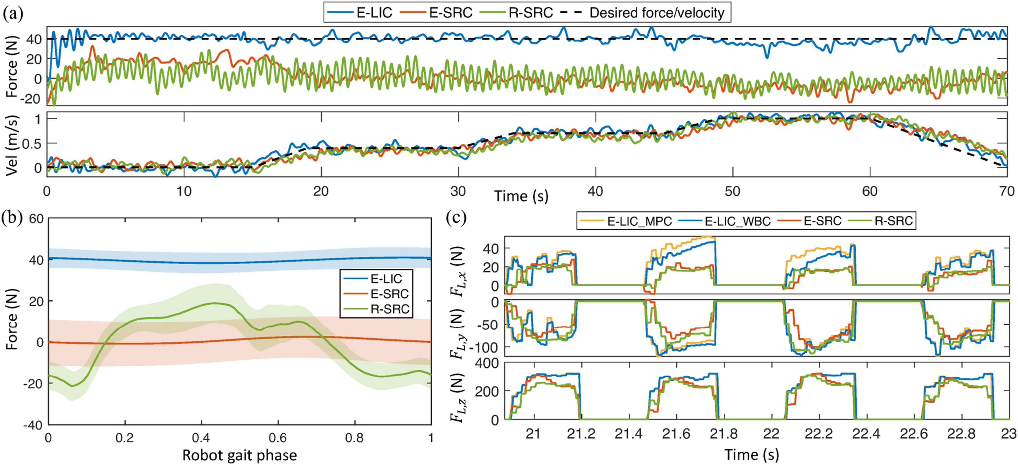
Figure 11(c) further compares the GRFs under different control strategies. Under the E-LIC condition, the GRFs computed by the loco-interaction MPC differed notably from those obtained with the static controller (E-SRC and R-SRC). To generate forward interaction forces, the Centaur robot produced greater x-direction GRFs for propulsion and increased vertical GRFs to counteract sagittal-plane moments. These results demonstrate the capability of the proposed loco-interaction MPC to actively modulate GRFs for coordinated force control and trajectory tracking. Furthermore, under the E-LIC condition, the GRFs refined by the WBC exhibited smoother and more finely tuned profiles than those generated by the MPC. This is due to the high-frequency update and real-time optimization of the proposed WBC, which complement the low-frequency MPC by providing more continuous and precise control commands under dynamic human-Centaur interaction. The refinement is more evident along the x-axis because the MPC adopts a constant-velocity assumption over its prediction horizon, whereas the WBC continuously optimizes based on real-time state feedback, leading to more accurate and smooth GRFs in the forward direction, where the primary human-Centaur interaction occurs.
Load-carriage experiment
Experiment setup
To assess the load-assistance performance of the Centaur robot during human load-carriage walking, we conducted experiments focusing on three key aspects: load redistribution, energy expenditure, and gait characteristics. Load-sharing performance was evaluated through insole pressure measurements (Pedar-X, Novel, Germany), which reflect the actual ground reaction forces borne by the human and the proportion of load transferred to the Centaur robot. Metabolic cost was quantified using the Brockway equation (Brockway, 1987) based on data from a wearable gas analyzer (Cosmed K5, Rome, Italy), providing a direct measure of human energy consumption. To further assess gait stability and coordination, step width variability and center of pressure (CoP) variability were analyzed as indicators of lateral balance control and gait consistency (Park et al., 2023a), revealing potential disruptions from the human-Centaur interaction. Step width and its variability were computed from heel and toe marker trajectories recorded using a twelve-camera motion capture system (Motion Analysis, CA, USA). Step width was defined as the mediolateral distance between the feet at midstance, and its variability as the standard deviation across steps. CoP variability was calculated as the standard deviation of the mediolateral CoP position during the stance phase, also derived from the insole pressure data.
Five healthy subjects (3 male, 2 female, 165–178 cm, 54–77.5 kg) were involved in this experiment. The load-carriage walking experiment was conducted on a treadmill and consisted of four different stages in random order: (1) no equipment, no load (NE-0); (2) wearing the rigid-coupling Centaur robot with static reduced-order controller, 20 kg load (R-SRC-20); (3) wearing the elastic-coupling Centaur robot with loco-interaction controller, 20 kg load (E-LIC-20); and (4) wearing a regular backpack with a 20 kg load (B-20). The 20 kg load corresponded to 28.8% ± 4.03% of the participants’ body weight. Gait analysis was not conducted for the R-SRC-20 condition, as this intermediate configuration served to characterize load redistribution and metabolic outcomes under rigid coupling. During the E-LIC-20 condition, the desired horizontal interaction force between the human and the Centaur robot was set to 40.0 N. Before the experiment, subjects were required to conduct a pre-experiment to familiarize themselves with the experimental procedures and the use of the robot. During the experiment, the ambient temperature was around 25°C. In each experimental stage, subjects walked at a speed of 0.8 m/s for 5 minutes, with data from the last 3 minutes used to calculate metabolic cost and average insole forces. Subjects were given a 10-minute rest between each stage to avoid fatigue. At the start and end of the experiment, subjects were asked to stand and rest for 5 minutes to record the resting metabolic consumption.
The metabolic cost and insole forces were normalized by body weight for analysis. The net metabolic cost was calculated by subtracting the resting value. Step width variability was expressed as the coefficient of variation (CV), calculated by normalizing the standard deviation by the mean step width. To assess statistical significance, data normality was first evaluated. If all the conditions met normality, a repeated-measures one-way analysis of variance (ANOVA) was conducted (random factor: participant; fixed factor: condition), Greenhouse-Geisser correction was applied when sphericity was violated, and effect size was reported as partial η2. Post-hoc comparisons used paired t tests with the Holm-Šidák correction, with effect sizes reported as Cohen’s d z . If normality was not satisfied, the Friedman test was used instead, and effect size for the omnibus test was reported as Kendall’s W. Post-hoc comparisons in this case were conducted using the Dunn-Bonferroni test, with effect sizes reported as rank-biserial correlation r. Statistical significance was defined as P < 0.05 for all analyses.
Results
Figure 12(a) shows the changes in insole force during walking under different experimental conditions. The mean insole force during the stance phase (ANOVA, P = 3.83 × 10⁻⁵, η2 = 0.895) and maximum insole force (ANOVA, P = 6.05 × 10⁻⁵, η2 = 0.920) changed statistically significantly across all conditions. As seen in Figure 12(a) (i), compared to the B-20 condition, both coupling forms of the Centaur robot (E-LIC-20, R-SRC-20) reduced the insole force distribution during human walking. From the early loading response phase to the terminal stance phase, the insole force was lower than in the B-20 condition. Specifically, in the E-LIC-20 condition, the mean insole force during the stance phase was reduced by 9.78% ± 2.82% (paired t test, P = 7.52 × 10⁻³, d
z
= −3.865), and the maximum insole force was reduced by 11.03% ± 1.88% (paired t test, P = 4.16 × 10⁻³, d
z
= −4.259) compared to the B-20 condition. In the R-SRC-20 condition, the mean insole force during the stance phase decreased by 13.11% ± 5.46% (paired t test, P = 0.0158, d
z
= −2.983), and the maximum insole force decreased by 14.39% ± 5.51% (paired t test, P = 0.0136, d
z
= −2.870). No significant differences in the mean (paired t test, P = 0.196, d
z
= 0.776) and maximum (paired t test, P = 0.188, d
z
= 0.793) insole forces were observed between the E-LIC-20 and R-SRC-20 conditions. This result reflects that the softening elastic coupling predominantly modulates horizontal interaction dynamics, with vertical load sharing remaining unaffected by the coupling configuration. Load-carriage experiment results. (a) Insole force for different participants under four conditions. (i) Insole force profile of the left leg over one gait cycle. The gait cycles are segmented by the heel strike of the left leg. The average insole forces across one gait cycle for different participants are depicted with different colored curves, with the shaded areas representing the standard deviation. (ii) Mean insole force during the stance phase of the left leg. (iii) Maximum insole force of the left leg. (b) Net metabolic cost under four conditions. (c) Step width and CoP variability under three conditions. The step width variability is represented in the form of the CV, normalized by the average. In all bar plots, the bars and error bars represent group means and standard deviations across participants. Asterisks indicate statistical significance (P < 0.05), while “ns” denotes no significance.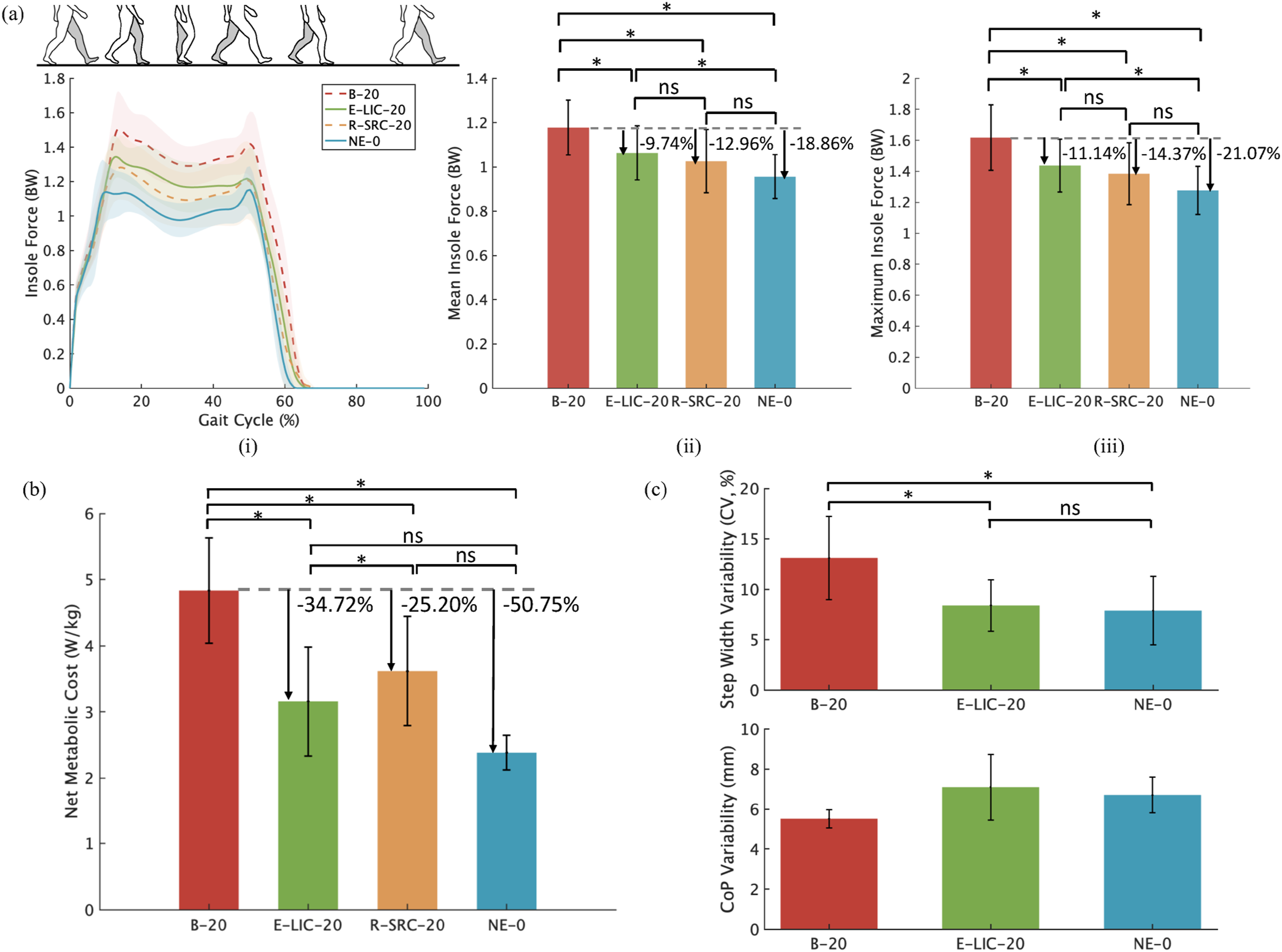
It is evident that the insole force under the NE-0 condition was the lowest. Compared to the B-20 condition, the mean and maximum insole forces were reduced by 18.84% ± 2.26% (paired t test, P = 1.06 × 10⁻³, d z = −6.717) and 20.99% ± 2.13% (paired t test, P = 1.69 × 10⁻³, d z = −5.699), respectively. Using the NE-0 condition as a baseline, the load-sharing ratio of the Centaur robot was quantified by comparing the net increase in insole force during the E-LIC-20 condition to that observed in the B-20 condition, both relative to unloaded walking. The results indicate that the Centaur robot can share an average of 52.22% ± 15.52% of the load pressure and reduce the maximum net load pressure by 52.45% ± 6.73%.
The net metabolic cost showed significant differences across the various experimental conditions during load-carriage walking (ANOVA, P = 2.25 × 10⁻⁴, η2 = 0.721). The net metabolic costs were measured as 4.83 ± 0.80 W/kg, 3.16 ± 0.71 W/kg, 3.62 ± 0.82 W/kg, and 2.38 ± 0.26 W/kg for the B-20, E-LIC-20, R-SRC-20, and NE-0 conditions, respectively, as shown in Figure 12(b). Compared to the B-20 condition, the metabolic cost under the E-LIC-20 condition was significantly reduced by 1.68 ± 0.24 W/kg (35.16% ± 4.95%) (paired t test, P = 5.56 × 10⁻⁴, d z = −7.924), while the metabolic cost under the R-SRC-20 condition was reduced by 1.22 ± 0.42 W/kg (25.47% ± 8.00%) (paired t test, P = 2.89 × 10⁻³, d z = −3.251). Additionally, a direct comparison between E-LIC-20 and R-SRC-20 revealed a further reduction of 0.46 ± 0.21 W/kg (12.69% ± 4.95%) under E-LIC-20 (paired t test, P = 0.0246, d z = −2.430). These results confirm that the Centaur robot effectively reduces the metabolic cost during load-carriage walking, and the further improvement observed under the E-LIC-20 condition demonstrates the essential contribution of horizontal force assistance.
The gait-related results under three conditions are presented in Figure 12(c). Step width variability exhibited significant differences across the three experimental conditions (ANOVA, P = 2.75 × 10⁻³, η2 = 0.901). The lowest variability was observed under the NE-0 condition, while the highest occurred under B-20 (paired t test, P = 5.79 × 10⁻³, d z = 3.619), indicating that external load increased lateral gait adjustments in response to destabilizing perturbations. In contrast, the E-LIC-20 condition significantly reduced step width variability compared to B-20 (paired t test, P = 7.92 × 10⁻³, d z = −2.983), and showed no significant difference from the NE-0 condition (paired t test, P = 0.344, d z = 0.537). These results demonstrate that the quadrupedal human-Centaur configuration alleviates load-induced perturbations by optimizing load distribution, thereby reducing the need for compensatory lateral gait adjustments. Meanwhile, the comparable step width variability between E-LIC-20 and NE-0 suggests that the human-Centaur interaction, including forward assistance and minor perturbations in other directions, did not adversely affect lateral gait consistency.
In addition, no significant differences in CoP variability were observed across conditions (Friedman, P = 0.165, W = 0.360), indicating that participants were able to adapt to the gait perturbations introduced under different conditions without compromising overall gait stability. These findings further support that the proposed Centaur system improves metabolic efficiency without adversely affecting gait balance or coordination.
Discussion and conclusions
This work presents the Centaur robot for load-carriage walking assistance, detailing its design, modeling, control, and experimental evaluation. The Centaur robot integrates elastic coupling with humans to form a quadrupedal load-carriage system, combining vertical load-sharing and horizontal forward force to achieve load-carriage assistance. Experimental results demonstrate that the Centaur robot can collaboratively walk with the human across various daily terrains, adapt to different walking directions and speeds, and provide stable horizontal forward force assistance, achieving a 52.22% ± 15.52% load-sharing ratio and a 35.16% ± 4.95% reduction in metabolic cost, without compromising gait stability. This novel load-assistive robot holds significant potential for applications such as emergency rescue operations and industrial tasks, offering transformative improvements in productivity for load-carriage tasks.
Load-assistive performance
Comparison of wearable load-carriage assistive robots. For the Assistance mode, LS represents load support, FA represents forward force assistance acting through the CoM, and JA represents joint torque assistance. An asterisk (*) indicates that the data were estimated from the information provided in the respective articles. n.r. denotes data that were not reported and could not be estimated from the available information with reasonable accuracy, while − indicates that the metric is not applicable or does not exist for the robot. The estimated load-sharing ratio is calculated as the ratio of the support force provided by the robot to the combined weight of the robot and the load. The metabolic effect metric indicates the percentage change in metabolic cost when using the robot compared to carrying an equivalent load with a backpack.
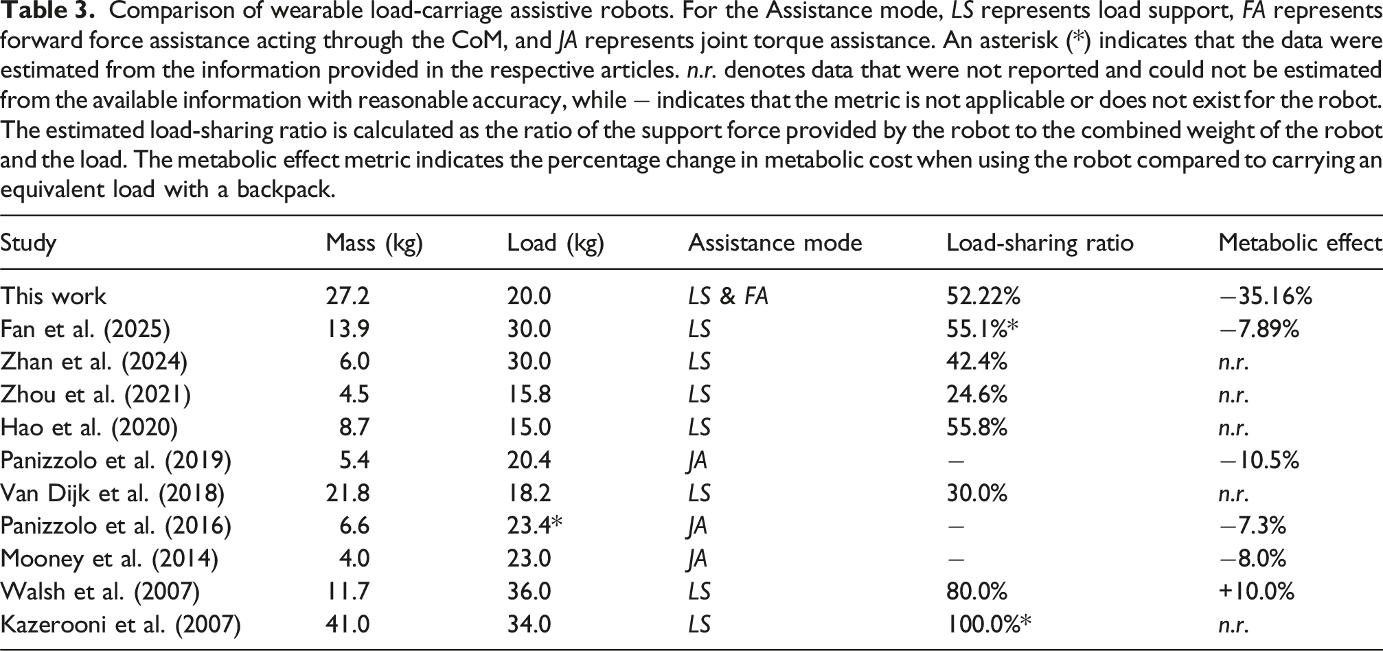
Furthermore, compared to joint-assistive exoskeletons, joint torque assistance often exhibits compensatory effects, with its efficiency diminishing as the load increases (Xie et al., 2021). For loads around 20 kg, joint assistance typically achieves only about a 10% reduction in metabolic cost. In contrast, the Centaur robot’s forward walking assistance, directly applied through the CoM of the human, offers a simpler and more intuitive approach that achieves significantly greater walking efficiency. Recent research on walking energetics has increasingly shown that mimicking biological joint torque assistance may not be the most effective strategy for reducing metabolic cost (Antonellis et al., 2022). Instead, directly assisting the human CoM has proven to deliver superior metabolic efficiency (Antonellis et al., 2022; Gottschall and Kram, 2003; Zirker et al., 2013). This perspective is supported by our experimental results, which show a 12.69% ± 4.95% reduction in metabolic cost under the E-LIC-20 condition compared to R-SRC-20, despite similar load-sharing performance. Notably, the Centaur robot is the first mobile wearable robot to provide load-carriage walking assistance by applying forward force through the human CoM. These findings validate the Centaur robot’s unique combination of vertical load-sharing and horizontal forward force assistance as a metabolically efficient approach for load-carriage walking assistance, with broad potential applications.
Limitations and future work
Despite the encouraging results of the proposed Centaur robot, several limitations may remain to be addressed in future work. First, the current elastic coupling mechanism enables compliant force control primarily along the horizontal axis. While collaborative motion planner helps mitigate disturbances in other directions, achieving multi-axis interaction control remains an important goal for further development. Prior designs like Wyss et al. (2018) have demonstrated multi-axis compliance but are too bulky for wearable systems. Future work may explore compact, multi-directional coupling mechanisms to improve full-axis compliance and interaction control.
Second, the proposed loco-interaction MPC assumes that the human walking states and interaction forces remain approximately constant within each prediction horizon. Based on this piecewise-constant assumption, the MPC predicts future reference trajectories and robot states for optimization, achieving effective interaction control when combined with the high-frequency WBC. Nevertheless, incorporating data-driven or model-based human motion and interaction prediction methods (Yu et al., 2022; Park et al., 2023b) could further enhance anticipative planning, allowing the MPC to leverage more accurate short-horizon forecasts for improved optimization. Moreover, the proposed loco-interaction control framework is not limited to the current Centaur prototype. The hierarchical and decoupled design allows adaptation to other wearable multi-legged robotic systems in future work.
Finally, the current implementation uses a constant force for horizontal CoM assistance. Future work will aim to optimize both the magnitude and temporal profile of the horizontal interaction force and to develop terrain-adaptive assistance strategies that further enhance energy efficiency and adaptability during load-carriage walking across diverse environments.
Supplemental material
Supplemental material
Supplemental material
Footnotes
Acknowledgments
The authors would like to thank Ping Yang, Yilin Mao, Tao Ye, Yuzhen Song, and Haifeng Liu for their assistance and support in conducting the real-world experiments.
Funding
The authors disclosed receipt of the following financial support for the research, authorship, and/or publication of this article: This work was supported by the National Natural Science Foundation of China [Grant U1913205]; the Science, Technology and Innovation Commission of Shenzhen Municipality [Grant ZDSYS20200811143601004, Grant KCXFZ20230731093401004], and in part by the High-Level Special Funds (G03034K003) from the Southern University of Science and Technology, Shenzhen, China.
Declaration of conflicting interests
The authors declared no potential conflicts of interest with respect to the research, authorship, and/or publication of this article.
Supplemental material
Supplemental material for this article is available online.
Appendix
References
Supplementary Material
Please find the following supplemental material available below.
For Open Access articles published under a Creative Commons License, all supplemental material carries the same license as the article it is associated with.
For non-Open Access articles published, all supplemental material carries a non-exclusive license, and permission requests for re-use of supplemental material or any part of supplemental material shall be sent directly to the copyright owner as specified in the copyright notice associated with the article.