
Abstract
Soft slender robots with high aspect ratios are prone to passive deformation due to gravity, rendering conventional kinematics ineffective and necessitating gravity compensation. Existing solutions often rely on multiple onboard sensors, which increase system complexity and reduce generalizability. This paper presents a bio-inspired real2sim2real framework that enables real-time gravity awareness and proactive joint-level compensation for portable, cable-driven soft slender robots—using only a single inertial measurement unit (IMU) and real-time simulation. In this method, an IMU affixed to the robot base captures orientation changes during quasi-static rotations. Simultaneously, the IMU readings are streamed to a robotic simulation platform established under the SOFA Framework, where the direction of virtual gravity is dynamically updated. To counteract undesired deformation caused by rotated gravity, we use a quadratic programming (QP) solver to continuously compute the necessary joint space motions that actively negate the virtual deformations. These motions are then executed in both the virtual and physical robots, forming a real2sim2real architecture. Experiments validate the effectiveness of the framework, achieving a compensation recovery rate (correlation coefficient) exceeding 99% in static cases, and 94% in low-motion dynamic cases. This novel method enables soft robots to maintain rich state estimation and configuration consistency under varying gravity by leveraging advanced soft body simulation, thereby minimizing reliance on physical sensors. Our method offers a generalizable and scalable solution for gravity-aware control in soft robotics.
Introduction
Soft slender robots have rapidly advanced in recent years, showing great potential for surgical applications (Kwok et al., 2022; Runciman et al., 2019; Yasa et al., 2023). The slenderness and dexterity allow minimally invasive or even noninvasive access to the surgical sites, while the robot softness physically ensures irrefutable safety in human (patient)-robot interaction. When these slender robots are used, the aspect ratio, low moduli, and structural stiffness significantly affect their quasi-static configuration under gravity. Long soft robots distinctly exhibit passive deformation toward the gravitational direction (i.e., becoming saggy, see the left image in Figure 1(b)), as the gravitational potential energy prevails over their elastic energy (Xu and Simaan, 2008), or referred as the self-loading effects of gravity (Marchese et al., 2016). (a) Principle of how elephants sense gravity and head orientation through the inner ear system. The head motion alters the gelatinous-like otolithic membrane inside the macula and bends the hairs of the hair cells, generating electrical signals to the nerves. After that, the signal is transferred to the brain for processing. Our work is inspired by this physiological phenomenon. (b) Schematic diagram of the real2sim2real framework for soft slender robots. In an un-actuated state, a long-soft robot made from low-moduli materials will undergo passive deformation when its axial direction (the local “Z axis”) is misaligned with the gravitational direction (the global “−Z axis”). Our proposed framework computes closed-loop compensation joint space motions based on a single IMU and FEM-based simulation.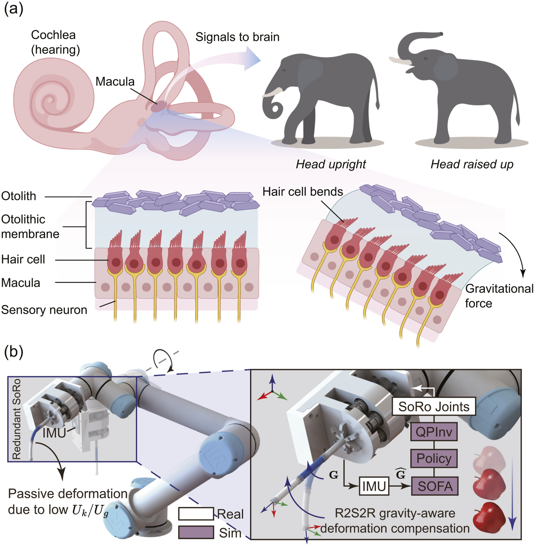
In most circumstances, people work on predictable, controllable soft robots that can eventually evolve into proprioceptive systems for unpredictable environments (Rich et al., 2018; Zhao et al., 2022). However, soft slender robots are highly susceptible to external forces that impact their shape. The robot’s own mass (viz., gravitational force) is a major dynamic factor to consider for its general motion tasks in 3-D space. This gives rise to an interesting tendency observed in the literature, wherein soft continuum robots are frequently oriented vertically with respect to gravity in practical implementations, likely as a means to mitigate the influence of gravitational forces. Therefore, gravity awareness and the corresponding gravity compensation mechanisms are crucial for effective motion planning and control of soft manipulators operating in diverse and dynamic environments. In the absence of sufficient stiffness, slender robots are unable to withstand gravity-induced deformations; likewise, without adequate sensing, they would fail to perceive the spatial configuration necessary for effective gravity compensation.
The field of soft robotics has presented numerous works addressing these concerns. For example, the development of stiffness variability by implementing jamming mechanisms (Cianchetti et al., 2014; Jadhav et al., 2022; Yang et al., 2021), antagonistic actuation mechanisms (Althoefer, 2018; Konda et al., 2022; Lai et al., 2022), and phase-change materials (PCMs) (Buckner et al., 2019) can make the soft slender robots substantially stiffer to against most external forces and gravity. The drawbacks are commonly acknowledged that jamming mechanisms and using PCMs would freeze the robots from major motions (Lin et al., 2024), which reduces the soft robots’ task space compliance, despite the fact that it can be improved by introducing localized stiffening (Bruder et al., 2023). Besides, both the jamming structures and the routing of PCMs complicate the mechanical design and pose challenges to robot miniaturization. An alternative approach is to utilize dynamic models that incorporate stiffness compensation or physical forces to address joint space control (Della Santina et al., 2020). Model predictive control (MPC) methods have been employed to regulate the motion of soft robots in gravitational environments. However, the presence of unknown and nonlinearly varying model parameters—such as stiffness and damping—often necessitates extensive physical experimentation (Hyatt et al., 2020), introducing ambiguity and uncertainty at the same time. A common approach to mitigate this challenge is to incorporate the robot’s perception into the control loop, which in turn requires effective robotic sensing capabilities. Taking soft robotics as an example, the sensory feedback used for MPC can be eye-to-hand vision in Bruder et al. (2020) (task space level), an electromagnetic sensor as a distal sensor in Cursi et al. (2021) (task space level), pneumatic pressure in Best et al. (2021) and Haggerty et al. (2023) (joint space level), strain sensors in Thuruthel et al. (2019) (configuration space level), optical trackers as distal/body sensors in Molnar et al. (2018) (configuration/task space level). Although they are not specifically developed solely for gravity compensation, these methods often account for the effects of gravity in the control. However, these methods are not well suited for portable applications in which the system’s pose varies over time. Such scenarios are frequently encountered, as soft robots are often deployed as subordinate modules within larger robotic systems.
To conclude, we list some typical measures for gravity compensation in rigid and soft robots in Figure 2. Rigid robots can go against gravity with the help of counterweights and springs and can compensate for the forces, including gravitational forces, through different control methods. Soft robots can withstand gravity by enhancing their own stiffness through different methods, such as the use of PCMs (e.g., low melting point alloy (LMPA) (Peters et al., 2019), thermal responsive materials (e.g., liquid crystal elastomer (LCE) (He et al., 2019)), and jamming mechanisms. Even though it is challenging, soft robots can also be actively controlled by exploiting the dynamic models (Luo et al., 2024) and physical/model-based simulation (Caasenbrood et al., 2024) with explicit predefined parameters. Model predictive control (MPC) can employ real-time sensory data for active robot control, including in soft robots (Bruder et al., 2020). Our work utilizes physical simulation and a single sensor to achieve gravity compensation online.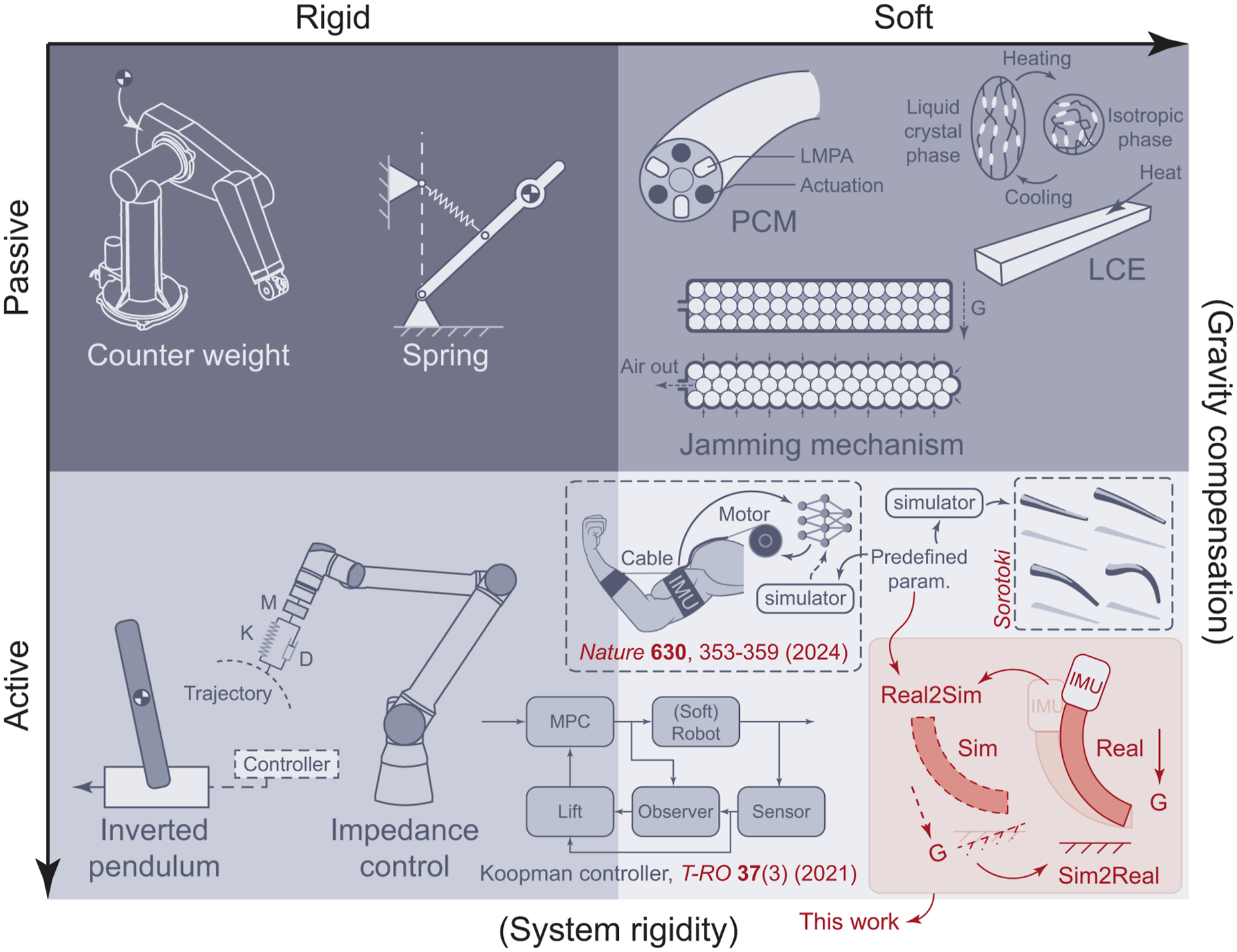
Specifically, we notice a striking trend of employing inertial measurement unit (IMU) sensors on soft robots, and we are convinced that it is because they are low-cost, compact, and easy to deploy. The accessibility of finite-dimensional streaming data also reduces the computational cost for real-time response with the same computing power. Recent works have been creative in sensorizing soft robots with IMU sensor(s) for more possibilities. Even though commercial IMU chips are typically used to measure angular rate or body orientation, soft robotic researchers indirectly use them to measure many other parameters through modeling and learning-based approaches, including robot configurations (shapes) (An et al., 2024; Martin et al., 2022), forces (Ang and Yeow, 2022), stiffness (Lin et al., 2019), and so on, that benefit better motion planning and control. For instance, Martin et al. (2022) proposed using multiple IMUs attached to each link of a soft arm to approximate robot configuration based on the serially chained orientations. Despite the design complication, this method does provide an inexpensive and effective solution for soft robot proprioception. To improve the sensing fidelity and deal with the occlusion problems when using only eye-to-hand vision, Bezawada et al. (2022) presented a model-based method to reconstruct a soft manipulator’s shape through IMU-vision sensory fusion with Pythagorean Hodograph curve model. In Meng et al. (2023), researchers demonstrated the possibility of using a fusion sensing system that contains on-manipulator IMUs and conductive springs to obtain the major deformation of a soft manipulator for closed-loop control with sim-to-real transfer learning methods. The sensory fusion is excluded from the geometric-based simulation, so pre-trained networks are required.
It is worth noting that, based on our inexhaustive review of literature, most IMU-equipped soft robots utilize centimeter-scale IMU chips affixed directly to the continuum body, which increases system redundancy and limits general applicability. A clear implication is that such implementations are unsuitable for soft robots operating at smaller scales. The wiring and extra payload induced by the IMU make delicate manipulation tasks challenging. In addition, for soft robots with high aspect ratios (i.e., elongated structures), multiple IMUs are typically required to provide adequate spatial resolution for accurate shape reconstruction and motion estimation. Besides, conventional learning-based methods are, in general, prototype-dependent. Although the advancement of sim-to-real transfer learning reduces the prototype dependency by exploiting redundant synthetic data (Dubied et al., 2022; Lai et al., 2024; Meng et al., 2023), we argue that using more refined closed-loop physical simulations (Ferrentino et al., 2023) could further narrow the sim-to-real discrepancy with the assistance of real-world sensing. For this reason, real-to-sim-to-real (real2sim2real or R2S2R) transfer has been recently proposed (Lim et al., 2022; Wang et al., 2023) for different sensorimotor robot control. Yet, the real2sim2real framework has not been extensively explored in soft-bodied robotic control.
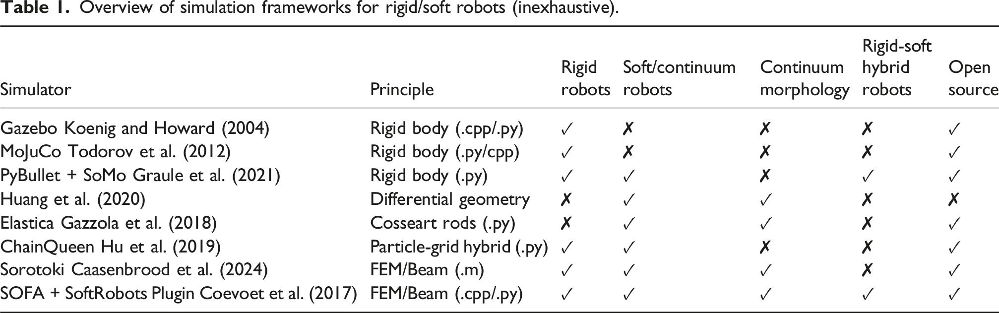
Overview of simulation frameworks for rigid/soft robots (inexhaustive).
This paper reports an IMU-based real2sim2real framework that enables real-time gravity awareness and proactive joint-level compensation on portable cable-driven soft slender robots to maintain the desired robot configuration. The framework is sketched in Figure 1. A compact footprint for cable-driven soft slender robots is presented.
The main contributions of this paper are as follows: first, we propose a novel control framework that utilizes only a single IMU in conjunction with real-time finite element simulation to enable gravity awareness and proactive joint-level compensation for soft slender robots with high aspect ratios ( > 10) and high joint dimensionality ( ≥ 6 cables). This approach eliminates the need for multiple on-body IMUs typically required by conventional methods, thereby enabling the reconstruction and control of longer robots with minimal sensor requirements for gravity compensation. Second, we introduce and validate a real-time reconstruction pipeline for virtual gravity, leveraging low-drift IMU readings enhanced through a unified solution that streamlines active temperature regulation and real-time filtering via an Extended Kalman Filter. This approach to IMU stabilization opens new opportunities for mono-sensor-based augmented sensing capabilities in soft robotic systems. Third, we present extensive experimental validation on a compact, portable, six-degrees-of-freedom cable-driven soft slender robot. The results demonstrate the proposed framework’s accuracy in motion prediction and compensation, as well as its potential for deployment in portable applications.
Simulation deployment
Simulation environment
A robophysical
1
simulation would be in favored in the proposed framework. In this work, the soft robotic simulation was established on the SOFA v22.06.99 using the SoftRobots plugin with Python 3.8. Since SOFA is primarily based on the finite element method (FEM) (Ferrentino et al., 2023), continuously altering the robot’s pose in a constant gravity environment will dramatically boost the computational cost. Instead, making the virtual robot standstill and changing the virtual gravity will be more efficient in terms of finite element computation. Moreover, we consider the cable constraints, which cannot be easily described through the other SOFA-ready models, such as the rod model. Here, we assume the robot has no contact with the external environment, but only constrained by the embedded cables (to be discussed in Section 2.2). To do that, the virtual gravity was first set to be 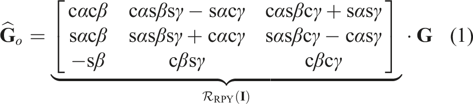
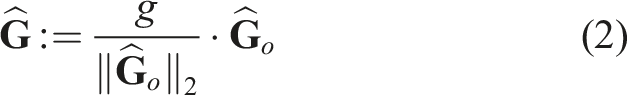
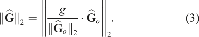
Using the property of norms ‖a ⋅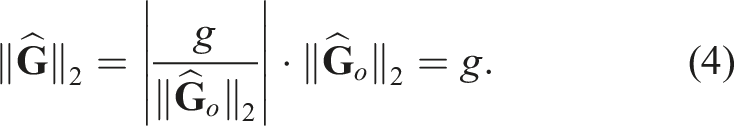
Normalizing the IMU readings ensures that the simulated rotating gravity can be treated as if the robot were rotating in a real gravitational environment with a constant gravity direction (toward the ground) and magnitude ‖ Therefore, the normalized virtual gravity should be updated as The change of virtual gravity reconstructs the pose change of the portable robotic system in the simulation and reduces the cost of finite element computations.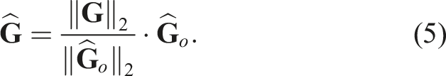
Virtual robot modeling
In SOFA, a soft object is loaded as a 3D volumetric meshed entity, and the robotization can be completed by defining geometric constraints to formulate a “joint-link” relationship. Regarding cable-driven soft robots, the constraints include cable distribution and actuation mechanisms. Here, we used the open-source Gmsh (https://gmsh.info/) (Geuzaine and Remacle, 2009) to mesh the soft robot’s 3D model.
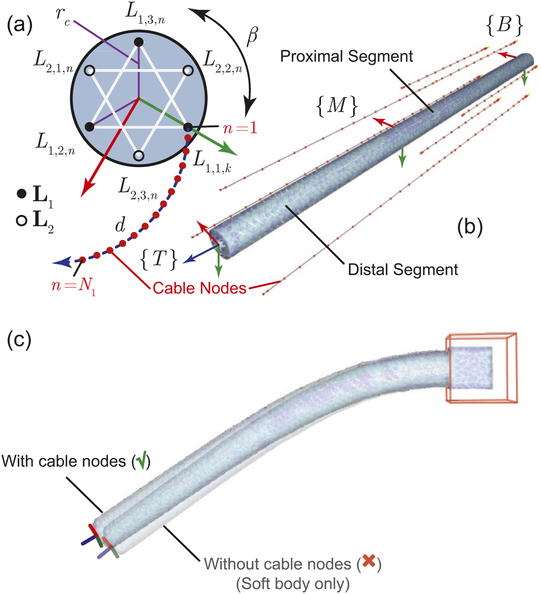
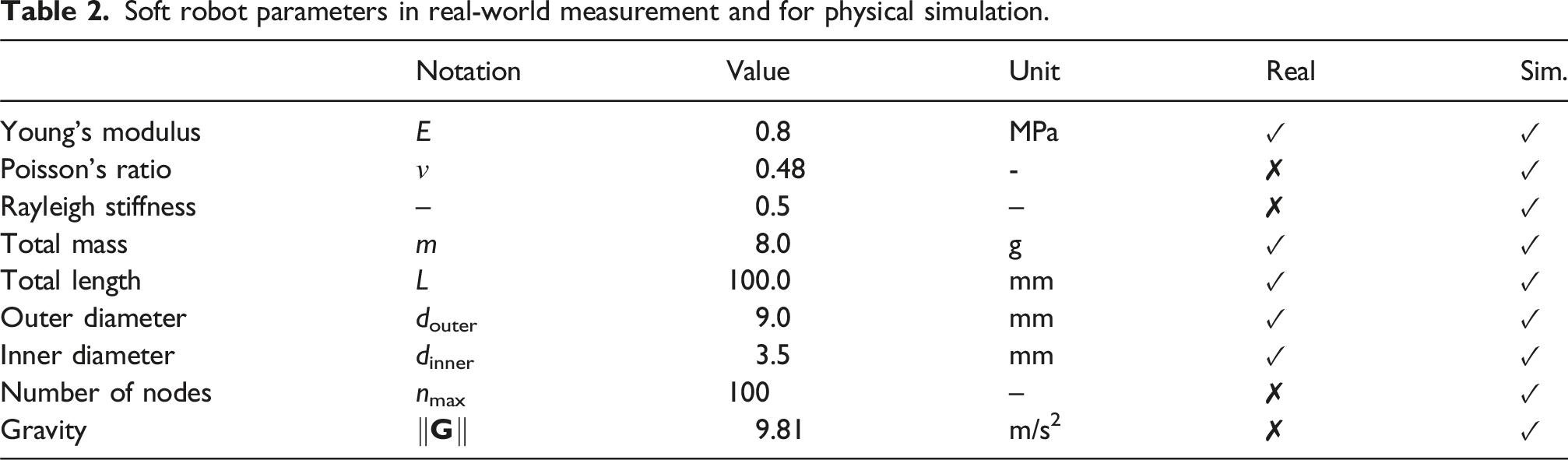
In this paper, we consider a classic two-segment soft robot with each segment driven by three equiangular distributed cables. The cables are not providing any extra pre-tension at the zero state. At the default (straight) configuration, the “insubstantial” cables can be geometrically defined by a number of 3D nodes with respect to (w.r.t.) a base frame {B}, which are governed by (a) Parameters of the virtual two-segment soft robotic model in a cross-section view. This is to model cable tension and robot deformation. (b) Exploded view of cables’ geometric constraints (in the form of cable nodes) of a meshed robot. (c) The defined cable nodes affect the robot configuration in the simulation—reflecting real-world behavior. The example below shows the same robot as in (b), both with cable nodes (untensioned) and without cable nodes, under identical conditions including physical parameters. Soft robot parameters in real-world measurement and for physical simulation.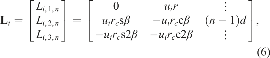

In SOFA, we employ linear elasticity mode as the constitutive law. We seek to compute the coupled cable (actuator) displacements 


Similarly, when considering the coupling of effector and cable joints (the cable nodes would have contacts to the effector, see Figure 3(b)), and substituting 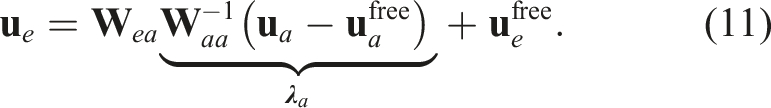
Here, equation (11) illustrates a linearized relationship between the contribution of the coupled cable displacement
QP-based inverse solving
For the run time inverse simulation, the quadratic programming with linear complementarity constraints (QPCC) based “QPInverseProblemSolver” (Coevoet et al., 2017) is used to build and solve an inverse problem set by combining end-effector and actuator constraints (refer to equation (11)). In our context, QP-based optimization is preferred over other inverse kinematics methods available in SOFA, as it offers better handling of constraints and improved robustness in scenarios involving soft body deformations. We hypothesize that the inverse solutions are correct enough to control the real-world robot we built, given the robot’s modeling and fine-tuned physical parameters. To reduce computational overhead, we modify the direction of gravity
Specifically, to determine the optimal contribution of the cable joint displacements 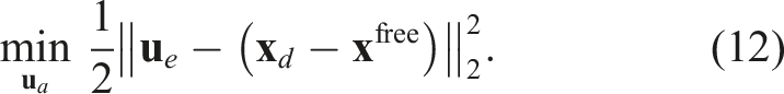
Substituting the expression for 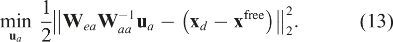
To simplify the objective function (see Appendix I), we define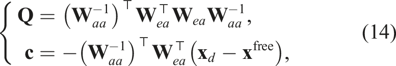
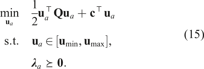
The constraint
Real2Sim2Real gravity-aware architecture
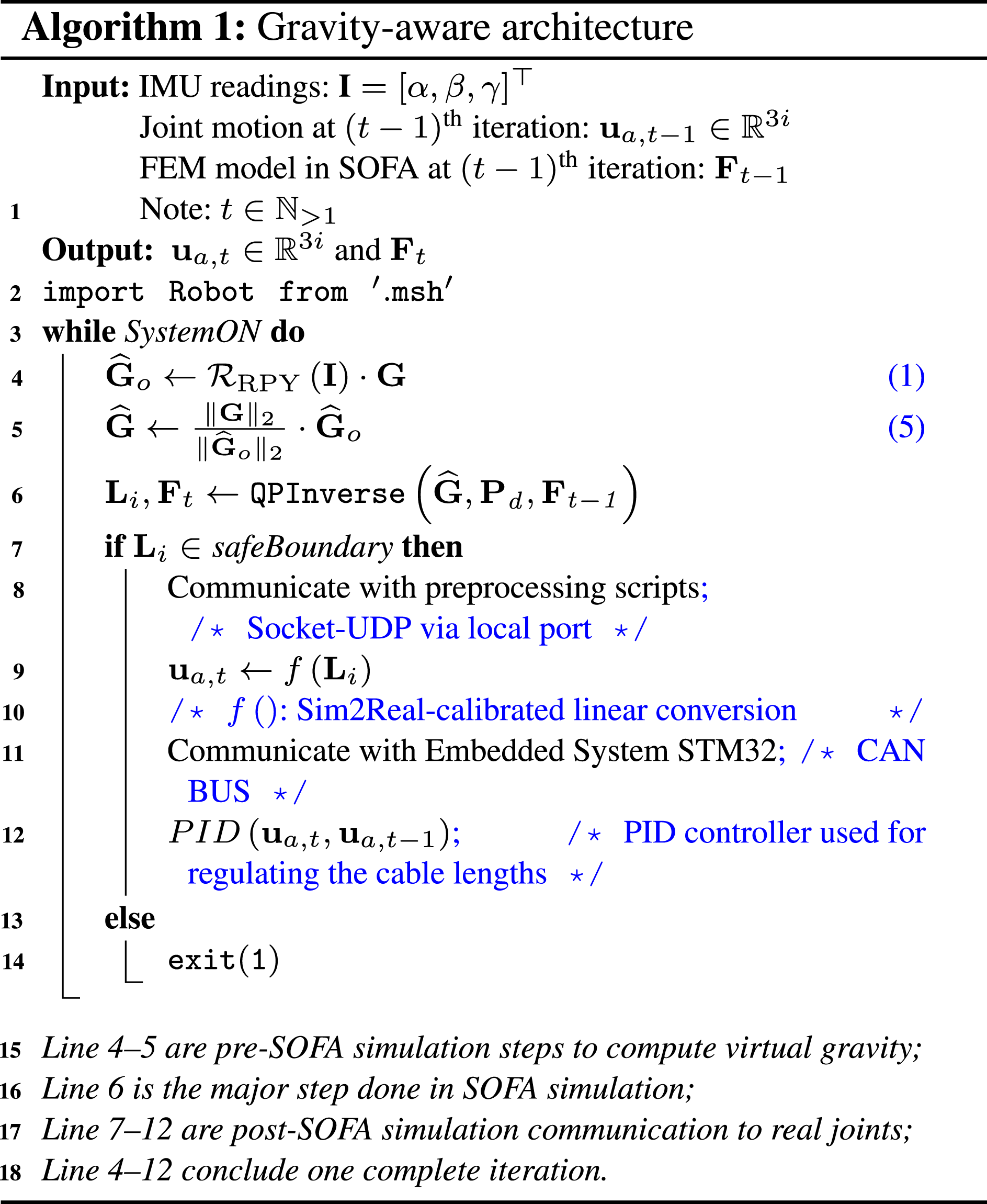
The precise orientation of the robot’s base—quantified in terms of roll, pitch, and yaw—is captured by an IMU mounted on the robot’s motor frame. This tri-axial data set is then processed by a Python script that calculates the relative direction of gravity based on predefined equations. The computed gravity vector, represented as
Within SOFA, when a desired position is assigned to the robot to reach, the gravity parameters can be utilized to determine the necessary displacement for each cable through the computation with QPCC. These cable displacements are critical for the accurate simulation of cable dynamics and are then transmitted back to the robot’s motors. By doing so, the motors are able to facilitate controlled movements of the robotic system, closely mirroring the simulated motion. This iterative feedback loop between real-world measurements and virtual simulations ensures a sync environment and robot motion from both ends. Precautious upper and lower boundaries are set (related to the desired maximum joint input for the soft robot) to protect the soft robot in case of motor malfunction or signal overload. For ease of understanding, the framework is simplified as below (see Algorithm 1).
System description
Interchangeable cable-driven soft slender robots
To verify the proposed framework, we designed a 6-DOF cable-driven soft slender robotic system to control a two-segment articulated robot. A design drawing can be found in Figure 4. The system adopts a compact, modular design for portability and manipulators’ interchangeability. As a result, soft manipulators with different lengths and stiffnesses can be conveniently detached and installed. Here, the manipulator’s design follows the dimension reported in Lai et al. (2022): each segment is 50 mm long and 9 mm in outer diameter. Therefore, this two-segment robot has an aspect ratio of over 11, which is iconic for validating our method. The segments with specific stiffness (Shore 50A) are 3D-printed from the digital mixtures of soft Agilus30 and rigid VeroClear photopolymers using a PolyJet printer (J826 Prime, Stratasys Ltd., USA), while the rigid caps are CNC-machined from acrylic glass. Fishing lines (∅0.7 mm Nylon) that are counterclockwise (as from the front) winded on the 3D-printed capstans are used as actuation cables. Mechanical design of the 6-DOF portable cable-driven soft robotic system. The manipulator can be replaced with that in different lengths and stiffnesses to test the proposed real2sim2real framework. (a) Exploded view. (b) Assembly view. An IMU can be attached to the bottom of the frame. (c) The assembled robot prototype. The soft robot naturally droops due to its gravitational potential energy being greater than its elastic potential energy.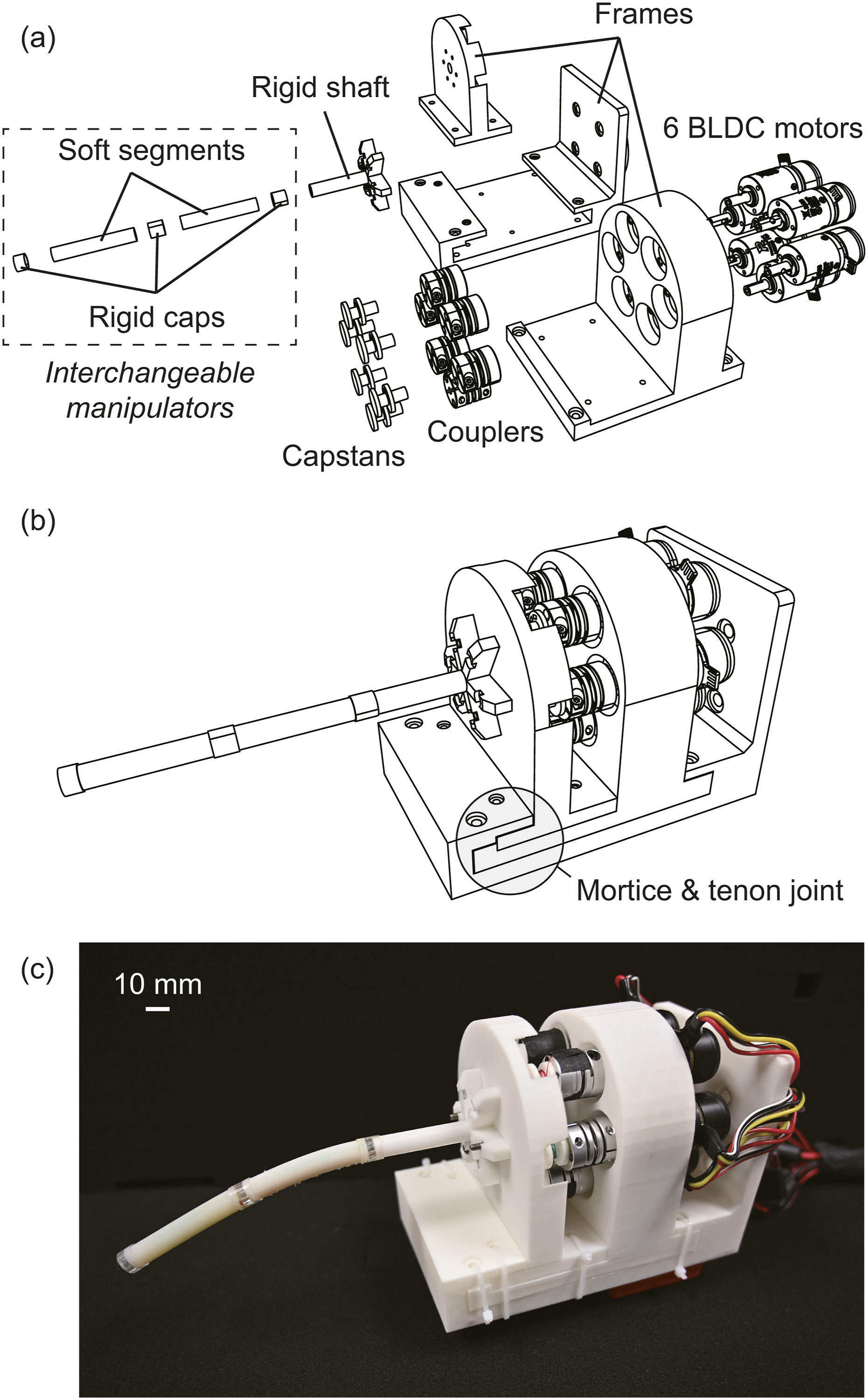
Regarding the actuators, six brushless direct current (BLDC) gear motors (M2006 P36, RoboMaster, DJI Technology, China) are concentrically mounted on a 3-D printed frame, and each motor is connected to a capstan via a flexible coupler. The capstans are responsible for pulling and releasing cables that control the robot’s motion. Each motor is connected to a BLDC speed controller that links to the same STM32-based microcontroller (Development Board Type C, RoboMaster, DJI Technology, China) in the CAN bus protocol. The robotic system is powered by a 22.8 V LiPo battery (TB48, DJI Technology, China). The IMU-equipped microcontroller is adhesive to the back of the frame to acquire the 6-axis orientation of the portable system. According to our assembled prototype, the robotic system alone, as shown in Figure 4(b), weighs 1.03 kg (the motors contribute 0.8 kg), which is suitable for hand held purposes or mounting on most collaborative robot arms.
Filters for IMU drifts
Since the microcontroller is equipped with a high-performance built-in IMU (BMI088 chip, Bosch Sensortec GmbH, Germany), we opted for the development board itself to act as the sensing unit instead of using additional IMUs. However, just like most IMUs, our setup also encounters drift problems due to ambient temperature and impact (Grewal and Andrews, 2010). Among them, temperature drift can be quite significant if the microcontroller undergoes long time operation. To get a more stable sensing performance, we modified the IMU on the algorithmic level.
For temperature drift, we employed proportional-integral-derivative (PID) control to actively heat up the chip and let it remain at a stable temperature. Specifically, the microcontroller accesses the chip’s temperature in real-time through high-speed serial peripheral interface (SPI) communication. Then, a 15°C temperature rise would be added to the read temperature, which formulates a target temperature for the IMU heating circuit to heat up (based on the PWM signal). This technique is typically used in outdoor drone applications (ArduPilot, 2024). The temperature gap would be then minimized by the PID controller.
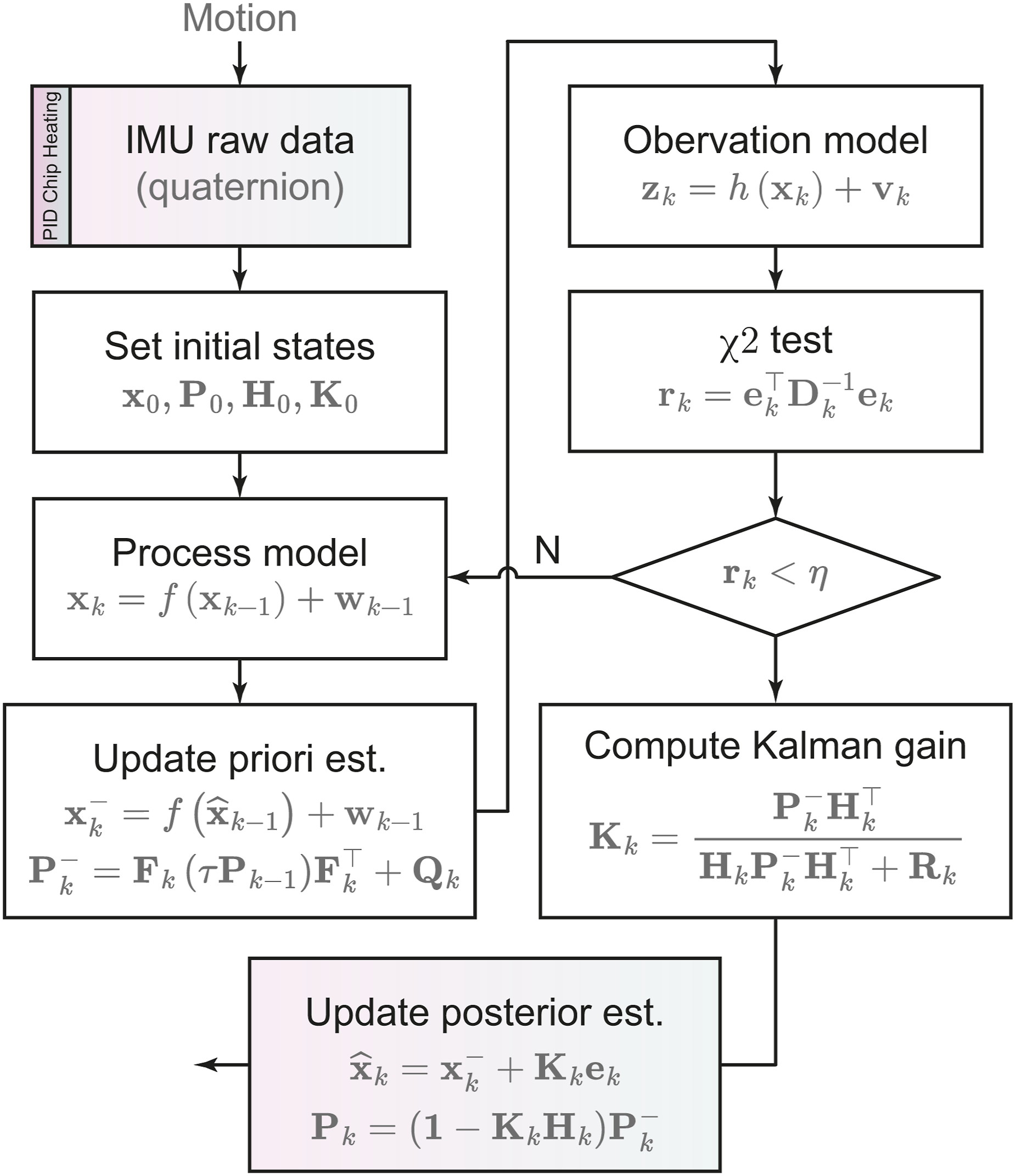
For drift caused by other factors such as possible unexpected impact and rapid movement, we utilized an extended Kalman filter (EKF) to observe and estimate the disturbed IMU orientation based on the previously mentioned temperature control approach. Specifically, we first defined the state vectors as 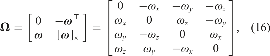
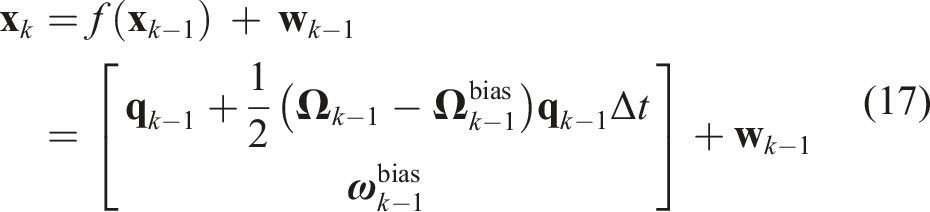

For the update phase of the EKF, the state transition matrix is computed by the Jacobian matrix of the process function EKF diagram for the IMU orientation estimation against drifts. See Appendix II for detailed explanatory notes.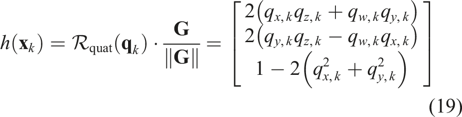
Real-time communication
The layout of our electronic design is given in Figure 6. The development board (microcontroller) is attached to the bottom of the frame that houses the motors, such that the 3D configuration of the whole portable system can reflect the 3D pose of the soft robot’s base. The microcontroller acts as a core electronic part of the communication among different components. It transmits IMU data to SOFA (by every 10 ms, or 100 Hz), guiding the spatial orientation of simulated gravity in real-time, while also managing the operation of individual motors. The design enhances the robot’s compactness, simplicity, and qualities, which are highly sought after in many portable systems. Electronic design of the 6-DOF robotic system. The command signals and information are transmitted through the CAN bus.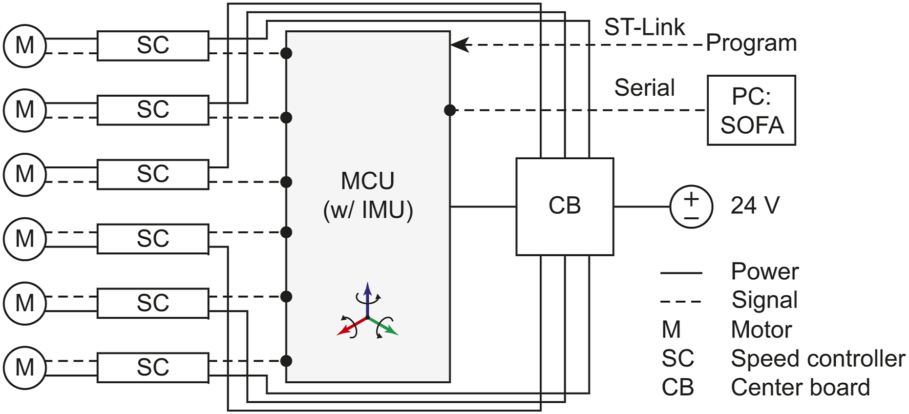
Experiments
IMU filtering
A reliable and accurate IMU output is a prerequisite for our robot control framework. To ensure this, the raw IMU data is first processed through our designed pipeline before being utilized in simulation. Therefore, we conducted ablation studies to evaluate the impact of PID-based temperature control and the EKF under both static (Figures 7(a)–(b)) and dynamic conditions (Figures 7(c)–(d)). Ablation study on IMU filtering performance. (a) Static scenario with temperature control, ablating EKF: significant drift is observed in the yaw angle over time. (b) Dynamic scenario with temperature control, ablating EKF: yaw drift becomes significant. (c) Static scenario with EKF, ablating temperature control: yaw error accumulates over time, though less severe than in the EKF-ablated case, error gradually enlarged. (d) Dynamic scenario with EKF, ablating temperature control: yaw drift is still present, but significantly reduced compared to the EKF-ablated condition.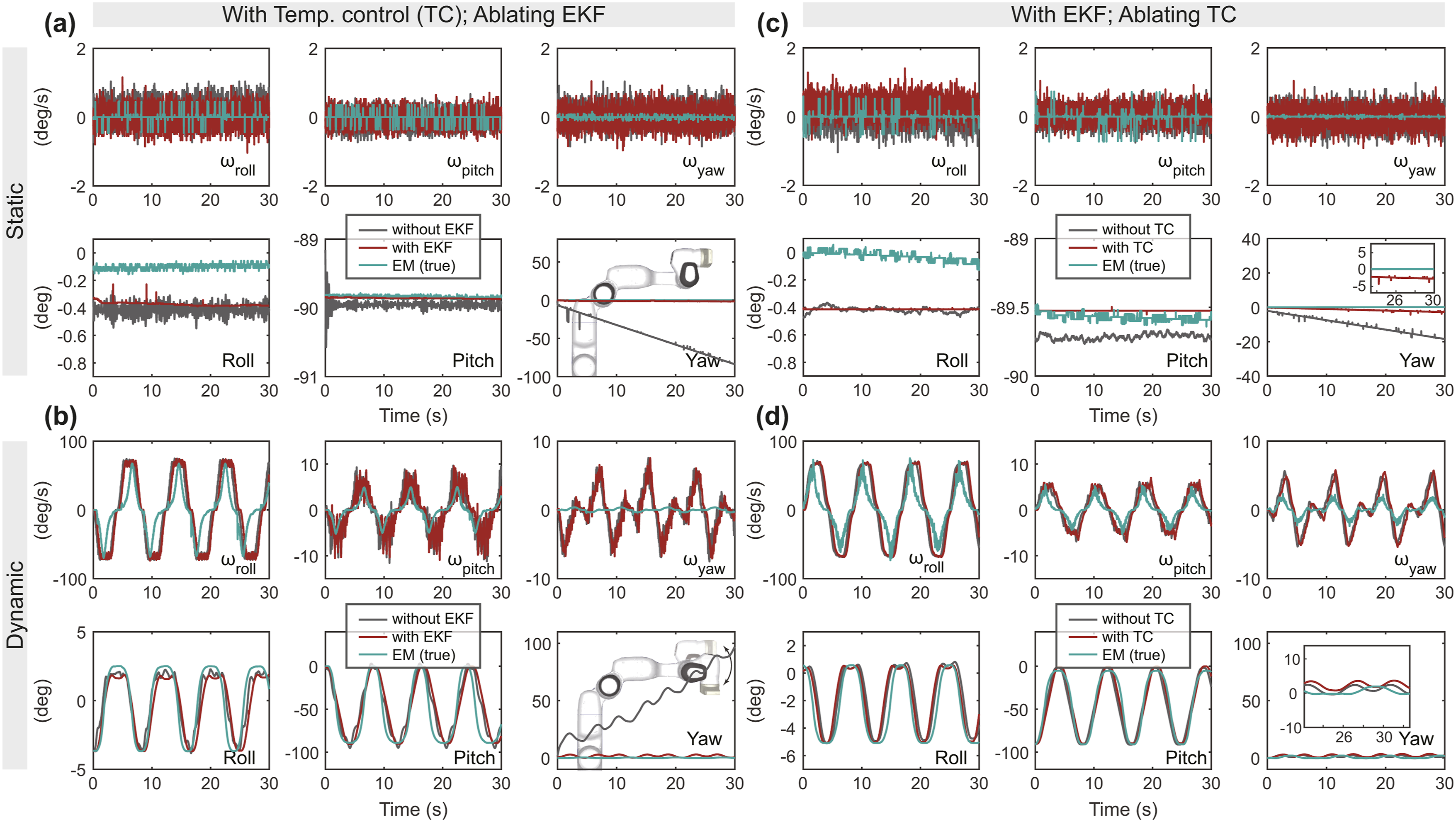
In our experimental setup, the microcontroller, equipped with an embedded IMU, was mounted on a robotic arm and connected to a PC for data acquisition. An EM tracker was employed to provide ground truth measurements. Each ablation was conducted with at least three trials; however, only one representative trial is shown here to maintain clarity in presentation. Figures 7(a) and (c) illustrate the static scenarios. While our filtering method does not fully eliminate angular velocity jitter (approximately ±1°), it effectively smooths the angular output. However, in both static cases, the yaw angle gradually diverges from the ground truth over time. As shown in Figure 7(c), the inclusion of the EKF module significantly stabilizes the angular readings and reduces yaw drift. Nevertheless, without temperature regulation, the yaw angle still accumulates an error of approximately 20° within 30 s (i.e., a total rotation within 9 min), underscoring the importance of thermal management for long-term IMU reliability. Figures 7(b) and (d) present the dynamic scenarios, where the robotic arm was programmed to perform a repetitive 90° elbow-only motion (joint 6) at an angular velocity of ∼23°/s. The results confirm that the EKF module plays a critical role in mitigating yaw drift and enhancing signal smoothness during motion.
These findings demonstrate that our processing pipeline significantly improves the stability of IMU angular readings in both static and dynamic conditions. The above-demonstrated results emphasize the necessity of both pre-processing (temperature regulation) and intra-processing (EKF filtering) to ensure trustworthy IMU data. Without these measures, natural drift—particularly along the yaw axis for long time operation—can lead to substantial errors, with potential deviations of up to 360° within a few minutes, which would severely compromise simulation fidelity.
Physical simulation fine-tuning
There is no doubt that physically simulated robots—governed by numerous but finite physical parameters—exhibit a noticeable sim2real discrepancy (Schegg et al., 2023). That is, the behavior of virtual robots can only approximate, but not exactly replicate, their real-world counterparts. This discrepancy can be mitigated by fine-tuning the major physical parameters within the simulator, including robot geometry and material properties. The previous sections have detailed the robot modeling process, including the representation of geometrical entities using a mesh model. This subsection focuses on the parameters fine-tuning procedure conducted prior to our robot experiments.
Before initiating the fine-tuning process, we first positioned the soft robot parallel to the ground, ensuring that both the robot tip and base, each equipped with electromagnetic (EM) sensors (3D Guidance trakSTAR, NDI), were free from cable tension, allowing the robot to adopt a naturally sagging configuration. We then recorded the resting position of the robot tip relative to the base (primarily along the Z-axis w.r.t. the robot base), to serve as a ground-truth reference for real-world behavior. The subsequent step involved adjusting key physical parameters in the simulation to replicate this sagging behavior, which is to produce a simulated robot configuration that closely matches the naturally bent robot shape observed in the physical robot.
In the simulation script, we selected two key parameters for fine-tuning: Young’s modulus and Rayleigh damping. This selection is informed by our empirical experimentation, which revealed that these parameters significantly influence the behavior of the virtual robot. Although Rayleigh damping is rarely specified in commercial material datasheets, it is widely used in structural dynamics to model energy dissipation due to internal friction. Based on our observations of the soft material’s behavior and also literature (Armanini et al., 2023), we believe this damping effect is a critical factor that significantly influences the robot’s simulated dynamics and should therefore be carefully calibrated to mitigate the sim2real gap. The fine-tuning workflow is illustrated by a chart shown in Figure 8(a). Physical simulation fine-tuning. (a) Flowchart of the fine-tuning procedure. (b) Heat map summarizing the temporal tip position error across 25 combinations of Young’s modulus ESOFA and Rayleigh damping CSOFA. The results highlight the parameter pair that best matches the real-world robot deformation. (c) Sim-and-real discrepancies in Z-axis displacement between the simulated and real robot tip positions, illustrating the degree of matching for selected parameter pairs from (b).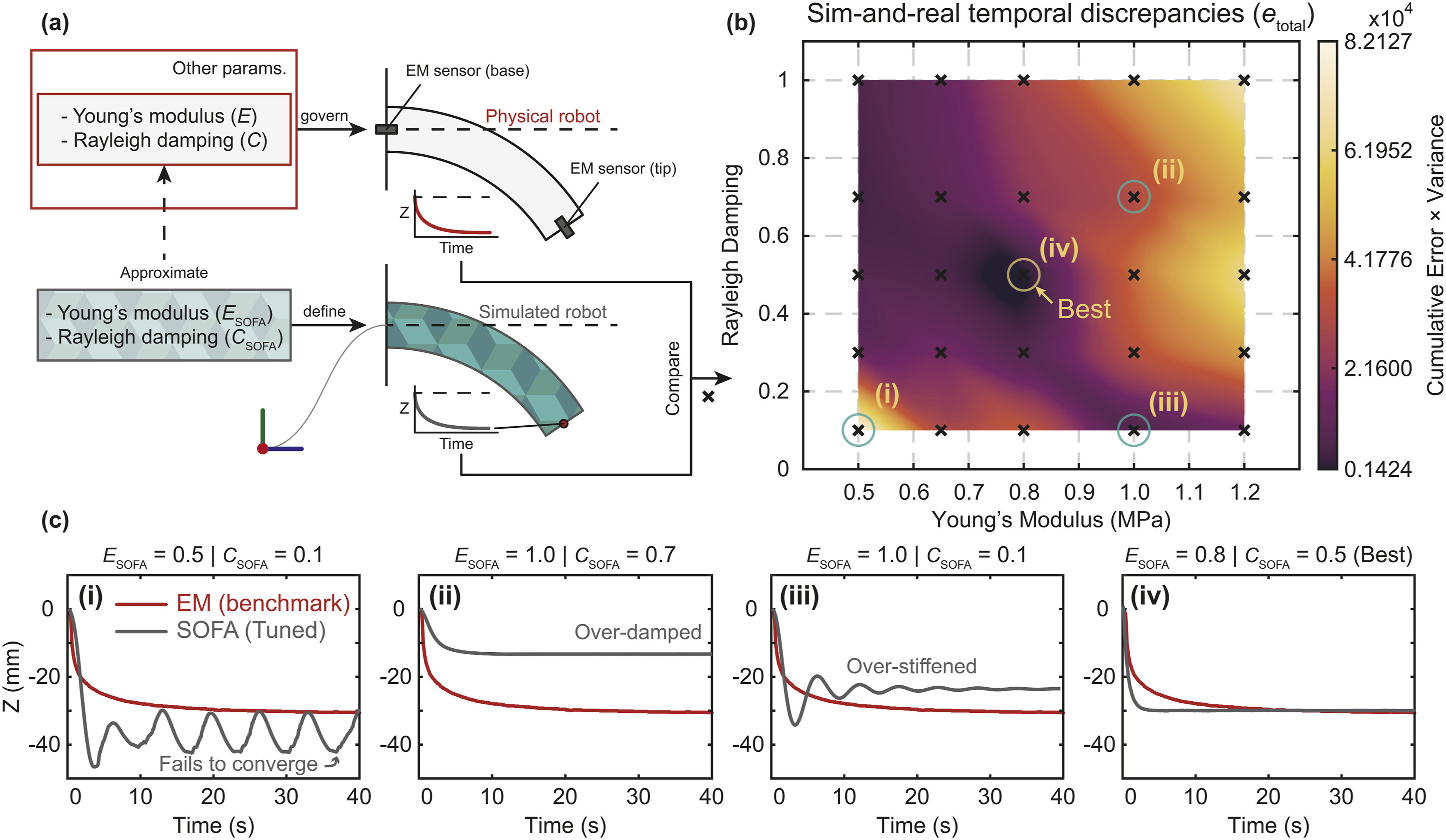
Guided by the material specifications (Stratasys Ltd., 2021), we narrowed the parameter search space and conducted 25 simulation trials to identify the optimal combination of Young’s modulus and Rayleigh damping. Specifically, Young’s modulus was varied as ESOFA = {0.50, 0.65, 0.80, 1.00, 1.20} MPa, and Rayleigh damping as CSOFA = {0.10, 0.30, 0.50, 0.70, 1.00}. In SOFA, Rayleigh damping can be defined via the Rayleigh mass and Rayleigh stiffness parameters, both of which are set to zero by default. To simplify the tuning process, we set these two sub-parameters to equal values and used their mean as CSOFA. To evaluate the accuracy of each simulation, we computed the temporal position error of the robot tip, defined as the product of the cumulative error over the time series and its variance: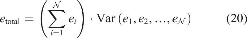
To visualize the physical response of the robot to the tuned parameters, we produced a heat-map of etotal, as shown in Figure 8(b), to highlight the sim-and-real discrepancy. The heat map applies cubic spline interpolation using
Real2Sim
Our hypothesis posits that virtual gravity in simulations can accurately represent the real-world robot’s free-space deformation, and that these simulated gravity compensation solutions are applicable in real-world scenarios. To validate this hypothesis and bridge the real2sim gap, we need to first verify the reliability of our simulation outcomes. For multi-axis sensing, we employed an EM tracking system to measure the position and orientation (6-axis) of the sensors affixed to the robot’s tip and base, serving as our ground truth. According to the specifications, the accuracy for sensor positioning and orientation is 1.4 mm and 0.5°, respectively. The IMU data was integrated into the SOFA framework in real-time, running on a PC equipped with an Intel i7-12,700 KF CPU. This setup yielded a dynamically responsive virtual robot, achieving an update rate of approximately 6 frames per second.
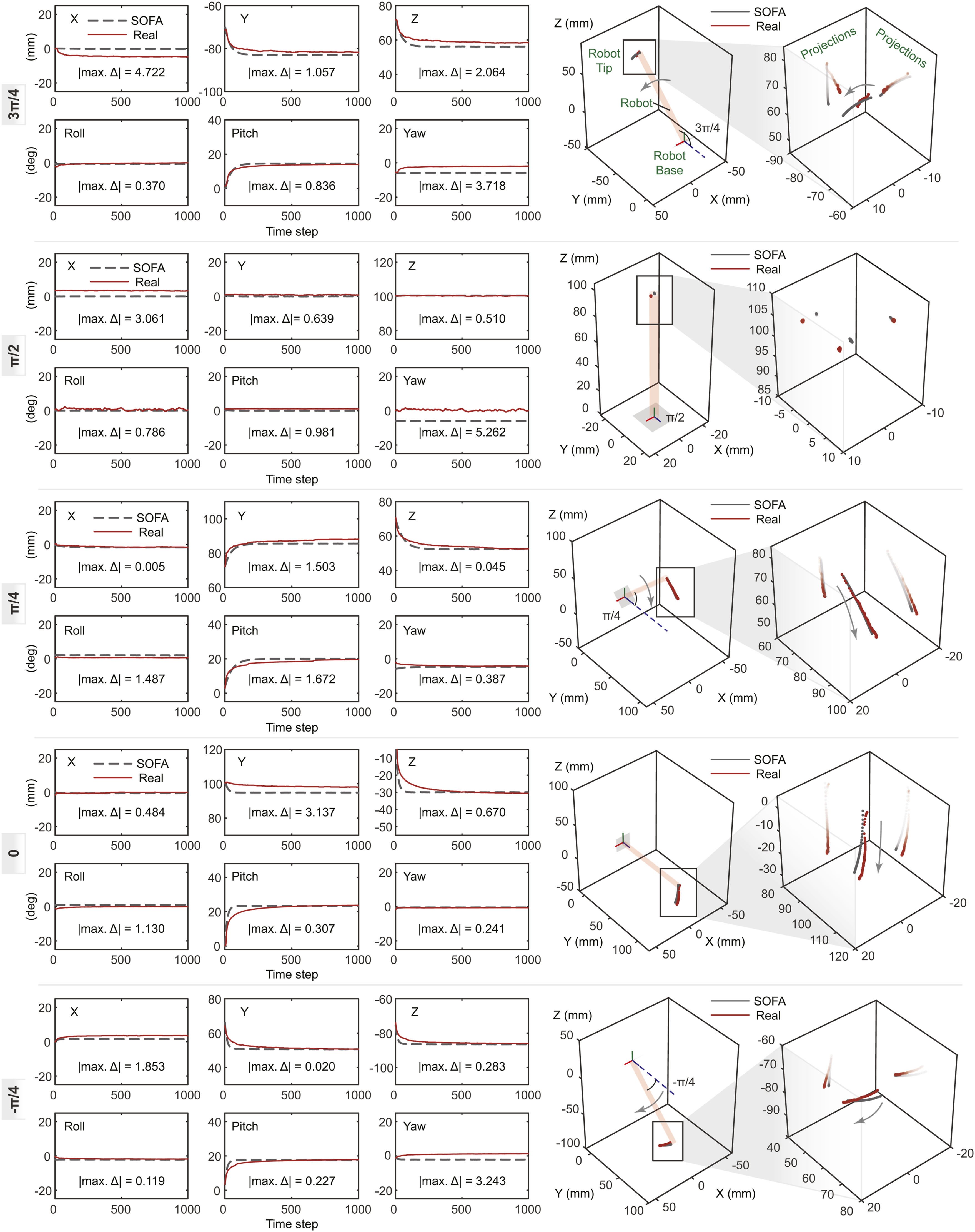
The closeup of our experiment setup is depicted in Figure 9. We positioned the portable robotic system at various inclinations toward the ground, specifically at angles of 135°, 90°, 45°, 0°, and −45°, to examine the deformation behavior of the soft manipulator deviating from its initial straight configuration. In the experiment, we dragged the robot tip to make it straight with the assistance of EM sensors’ reading. When the tip’s pose approached (0,0,100) w.r.t. the robot base, we released it for free fall and activated the simulation at the same time. Figure 10 presents the comparison results, illustrating that the simulation, based on real2sim gravity, accurately mirrors the real-world robot’s deformation, with negligible discrepancies at the distal tip—specifically, absolute errors within 4.7 mm in axial position (representing a relative error ≤4.7% with respect to the total length of the soft robot) and 5.2° in orientation. Furthermore, the results reveal a consistent match in temporal deformations between the simulated and actual robot behaviors. These minor errors are deemed inconsequential in the overall assessment of physical performance. Possible sources of these discrepancies include measurement inaccuracies (with the measurement system having a positioning accuracy of 1.4 mm), the added weight of the sensor at the tip, sensor wiring, and assembly inaccuracies. Experiment setup for the Real2Sim verification. This picture gives an example of the robot’s free space dropping when the system is parallel to the ground (i.e., 0°, as shown in Figure 10). The tip pose can be measured by the EM sensors. The experimental outcomes, juxtaposing the tip position and orientation of the SOFA-simulated robot (dashed dark lines) with the real-world robot (solid scarlet lines) in the absence of active actuation compensation across various initial inclinations toward the ground, are presented. The 100 mm-length soft robot exhibits natural deformation attributed to its slender structure, softness, and the force of gravity. These findings demonstrate that our simulated robot, under the influence of real2sim (interactive) gravity, can closely mirror the actual system configurations and soft robot deformation with minimal discrepancies.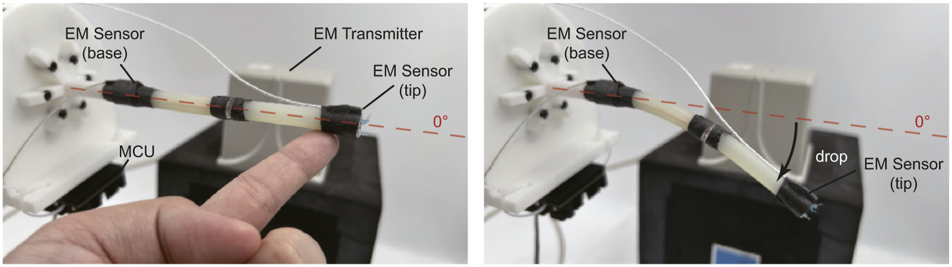
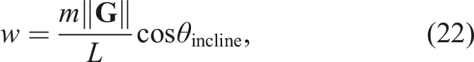
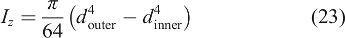
The traditional Euler–Bernoulli beam theory offers a framework for characterizing soft, slender, hollow robotic structures, akin to the one we introduce in this study. Nevertheless, it falls short of accurately capturing certain complexities, such as the tension forces within cables. While cable-driven continuum robots have been theoretically modeled as cantilever Kirchhoff beams (Boyer et al., 2020), the adoption of physics-based simulations facilitates a more straightforward articulation of cable constraints and the examination of asymmetric scenarios. Here, we provide a comparison of computed tip deflection between simulation-based and naive mechanics-based methods. We consider the soft robot to be a free-end hollow cylindrical cantilever beam. The beam’s weight acts as a uniformly distributed load. As such, the maximum deflection δmax can be computed by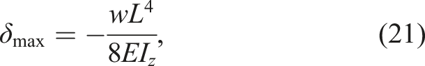
so that leave the static deflection of the robot tip when it reaches the equilibrium. We incorporate the theoretical maximum deflection into Figure 11 for ease of evaluation. The result highlights the reliability of our interactive real2sim pipeline in terms of quantitative and temporal capabilities. Its quantitative side can be judged by the significant reduction in deflection error of at least 83% over the simple cantilever beam modeling that demonstrates a much larger deflection using the same set of soft robot parameters in Table 2. The pictures in Figure 11 show the highly matched deformed robot’s appearance between virtual and actual robots in different system configurations. It can also be observed that the deformations in the 135-degree case and 45-degree case are slightly varied. Such variation is caused by the cable allocation inside the soft robot, as the cables opposed to the bending side are always stretched to resist the bending, and the longer cable provides a longer moment arm. It can be inferred that such variation can be very different when the robot bends toward different directions; and would be enlarged on higher aspect ratio robots. Variations of a similar kind are challenging to describe when using beam theory due to the complexity, but convenient to reproduce by FEMs. The gravitational-axis deflections of the robot tip computed in SOFA simulation, COMSOL simulation, and Euler–Bernoulli beam theory method, compared with the actual deflections measured by EM sensors. Each column gives a different inclination angle θincline toward the ground. 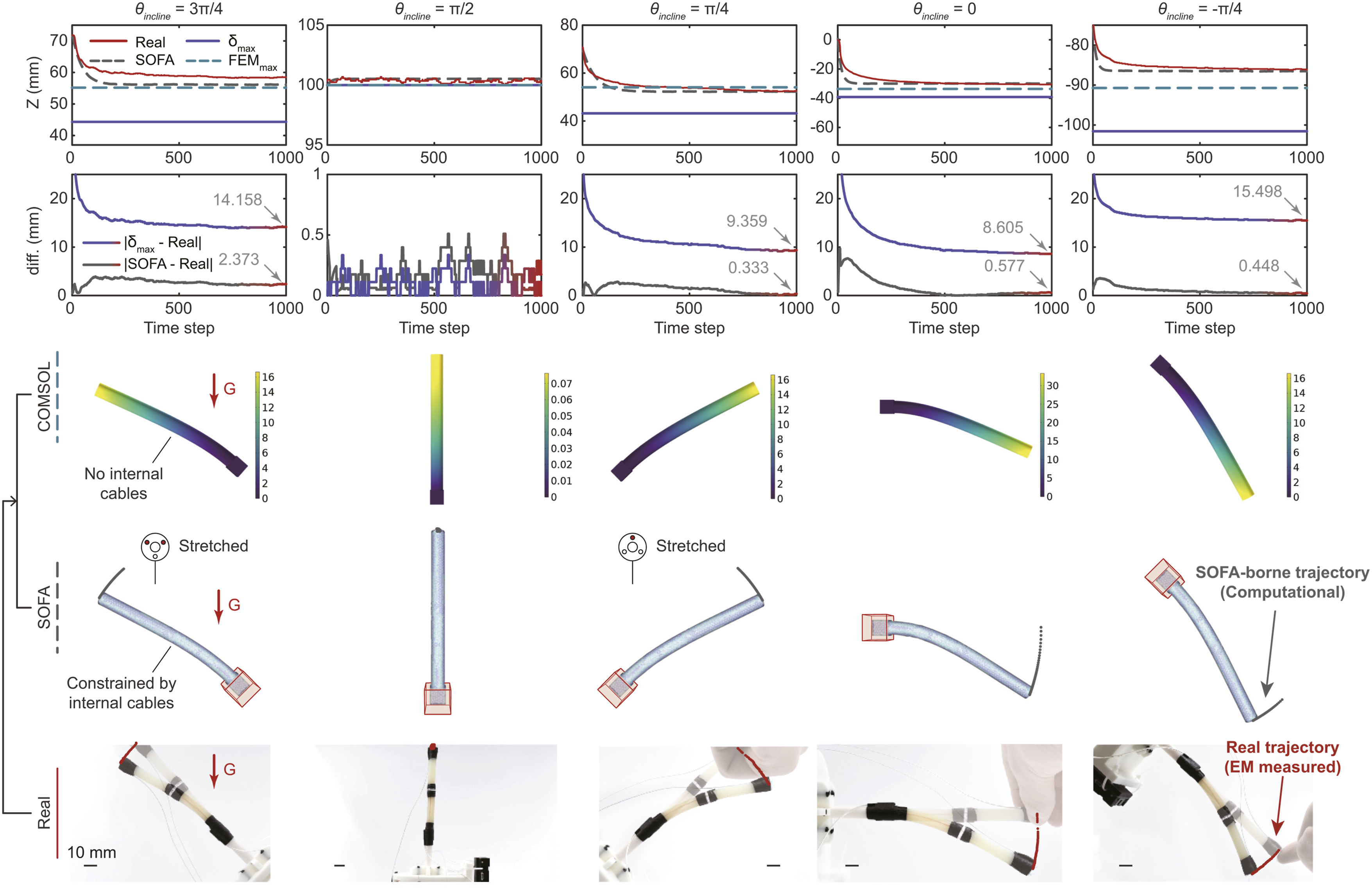
Beyond the SoftRobots plugins that facilitate the numerical computation of inverse kinematics and dynamics for cable-driven soft robots within the SOFA framework, the implementation of reduced-order finite element modeling improves the computing speed and showcases the potential for real-time deployment. For comparison, another general (commercial) FEM-based simulator, COMSOL Multiphysics v6.2, has also been put to the test. The simulator meshes our robot model into 4,039 tetrahedrons, while we use a more finely meshed model in SOFA with 4,788 tetrahedrons. Although we could not ensure a perfect match between the two, we made an effort to keep the mesh sizes/number as close as possible to enable a fair comparison. Other physical parameters used in SOFA have been replicated in the COMSOL simulator as much as possible, except for those that are not able to be defined. As shown in Figure 11, the COMSOL-computed deformations present similarities to what we obtained from the SOFA simulator and the experiments. However, it is observed that the results obtained from SOFA demonstrate marginally higher accuracy in comparison to those from COMSOL when aligned against experimental outcomes. This discrepancy may be attributed to the incorporation of cable constraints within the SOFA framework, but not readily available in other FEM simulation software. Besides, the computational time significantly varies: while the traditional mechanics-based and SOFA-based methods compute almost instantly, the commercial software takes minutes.
Real2Sim2Real: Static cases
Based on the confirmation that the configured SOFA simulation could reflect the real-world robot under static conditions, we proceeded to apply the gravity-aware control policy derived from the simulator to the actual robot, and such application was deployed online.
A series of controlled experiments have been designed and carried out for examination. The system architecture is shown in Figure 1. We first configured the physical robot with a certain angle (either known or unknown) w.r.t. the ground. Then, the IMU that adhered to the robot frame communicates with the virtual environment by updating the real-time 3D pose, which alters the virtual gravity’s orientation. A desired target tip location was assigned in the virtual environment. For ease of evaluation, in the experiment, we assigned a target location that could result in a straight robot configuration (i.e., (0,0,100) in {B} frame). After that, the QPInverseProblemSolver computes the joint motion that could correct the soft robot’s configuration with animated visualization in SOFA, which is simultaneously executed by the real motor joints. Related results can be found in Movie S1, and its snapshots are shown in Figures 12 and 13. Figure 12(a) presents the results for a horizontally posed robot using our proposed real2sim2real framework. We can see that the slender robot sags to a bent state after it loses physical support. As the simulator is simultaneously activated, the virtual robot also falls in the same direction (see Figure 12(b)). When the gravitational and elastic energy reaches an equilibrium, the bending stops, and the compensation starts effecting, gradually correcting the bent robot back to the 3D pose it is supposed to be. The EM sensor-measured tip position in the Y and Z axis is shown in Figures 12(c)–(d). The real measurements, once again, indicate that the actual deformation can be reflected by the virtual deflection. Although the sim2real discrepancy is relatively large at the initial stage, where the deformation is unstable and highly nonlinear, it finally converges to a minimum as the real2sim2real iteration continues—all relying on a single IMU attached to the robot footprint as a source of feedback. We also highlight the necessary time for our method to dent the discrepancy. In Figures 12(c)–(d), the gray shading refers to the period when gravitational energy dominates in the simulation, while the gray-and-red shading shows the same variables in the actual measurement. Here, the red shading stands for the sim2real delay (virtual peak to reality peak) of approximately 3 seconds. The visible real-world compensation motion appears at about the 6th second. We infer that such delay is related to the hysteresis that occurs in our soft robotic structure because of its slenderness and low-elasticity 3D-printed material. (a) The soft slender robot bends toward the ground upon losing its physical support from a human hand. By employing the proposed real2sim2real-based gravity aware framework, it gradually self-corrects its 3D configuration according to the real-time computation from (b) the simulated robot in the virtual environment. (c)–(d) The EM sensor-measured tip position in the Y and Z axis. The same reference frame is used in Figure 10. The X axis is not shown as there is no significant difference in such a planar motion. The red shading refers to the sim2real delay interpreted by the virtual peak to reality peak distance (Scale bars: 10 mm). The real-world robot autonomously reverts back to the straight/desired configuration when it employs the proposed real2sim2real framework. The tilted angles are (a) 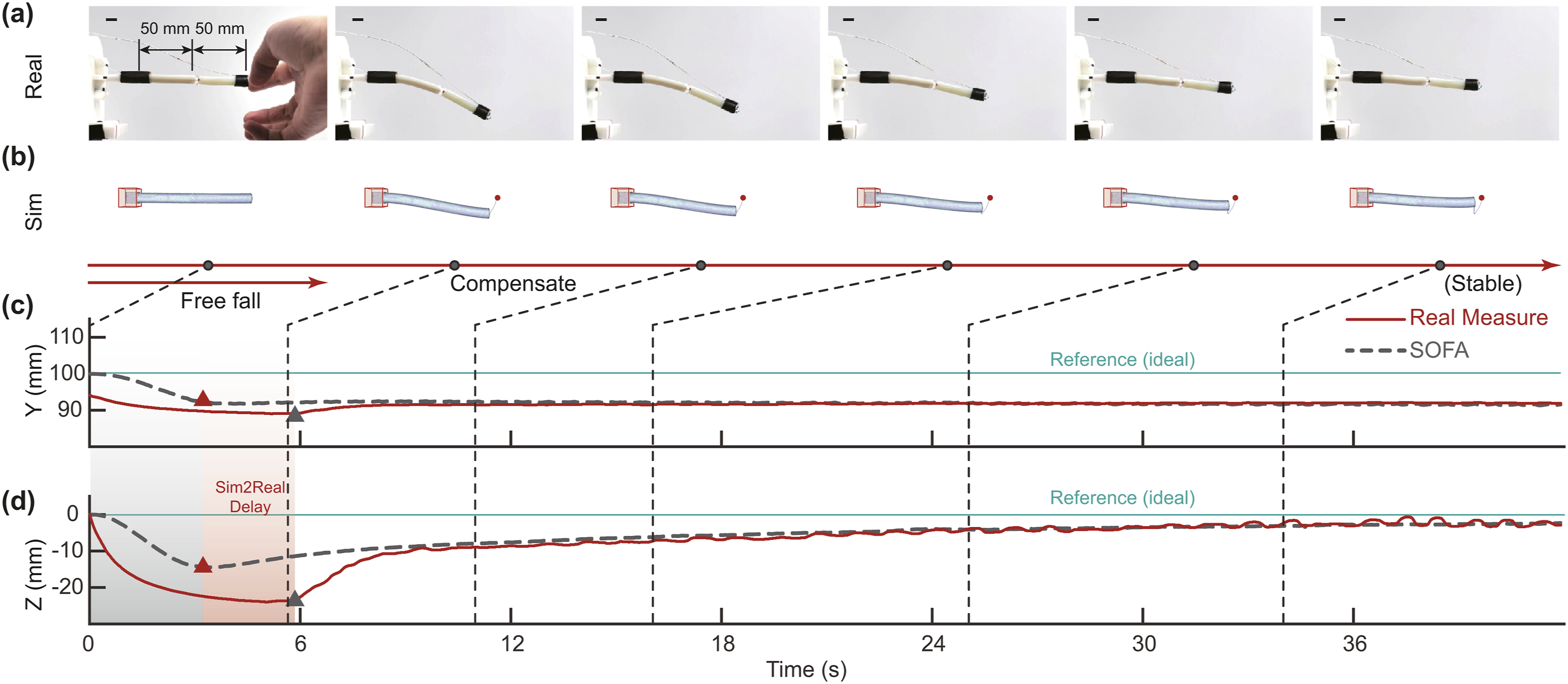
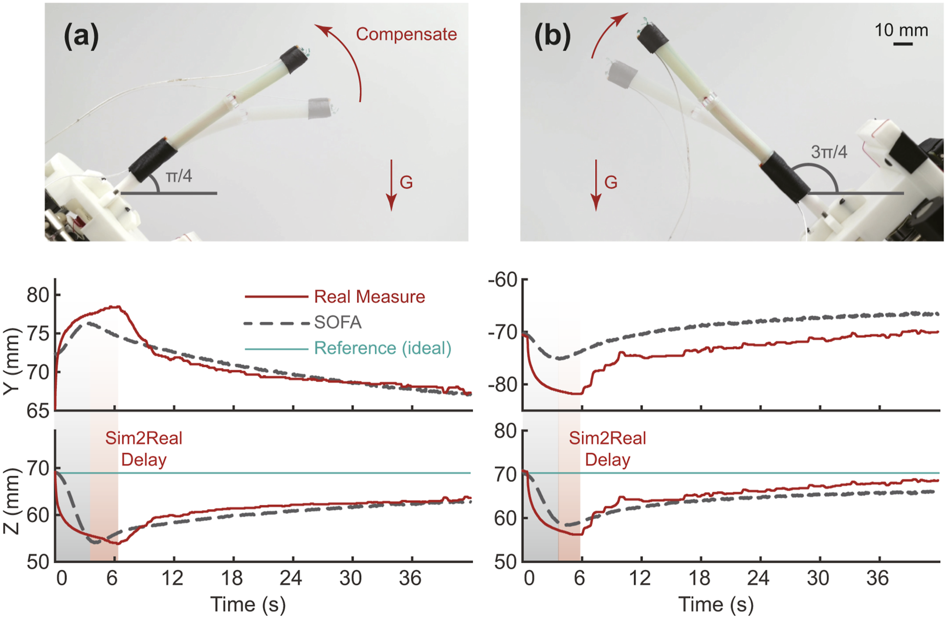
Figure 13 shows the results of repeated experiments with different spatial poses. It can be well noticed that, due to the cable allocation, these symmetric poses (
To further evaluate the generalizability of our method, we replaced the robot’s distal segment (originally 50 mm in length) with a longer segment measuring 80 mm. Without additional fine-tuning, but only updating the virtual geometry and cable node constraints, we repeated the same free-fall experiment illustrated in Figure 12. The results, presented in Figures 14(a)–(d), demonstrate that our method remains effective even with a more slender robot (Slenderness of 14.44). In the final stabilized phase, the virtual robot does not maintain a perfectly straight configuration after compensation, mirroring the behavior observed in the physical robot, where the midsection exhibits a slight downward deflection. When the robot is elongated, the weight of its own body, especially in the middle, causes it to sag under gravity. The longer the segment, the greater the moment arm, which increases the bending moment and leads to more pronounced deflection. The longer robot may also introduce slack or uneven tension distribution, cause a weak midsection. (a) The soft slender robot, with a longer second segment (80 mm), bends toward the ground upon losing its physical support from a human hand. (b) The simulated robot in the virtual environment. (c)–(d) The EM sensor-measured and the SOFA-predicted tip position in the Y and Z axis. (Scale bars: 10 mm).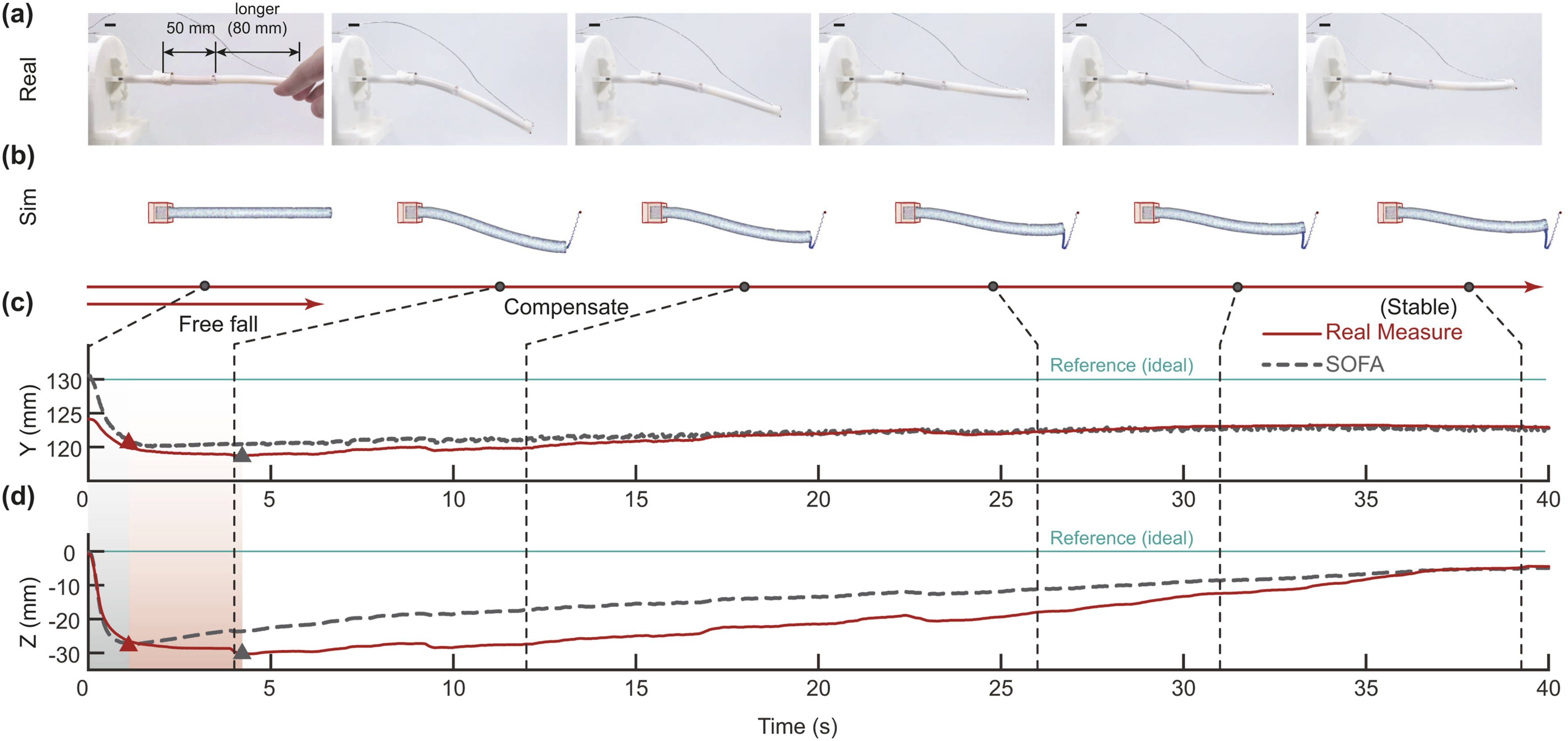
It would be hasten to add that, based on the results computed in SOFA and the real-world experiments, it is inherently impossible to maintain a perfectly straight robot configuration as desired (see the reference lines in Figures 12 and 13), regardless of the amount of actuation or compensation applied. Nonetheless, our results demonstrate that the simulated behavior closely matches the real-world measurements, indicating that the virtual robot (and its computed active joint-level compensation) accurately reflects the physical dynamics of the soft robotic system. Therefore, the comparison between the SOFA simulation and the real-world measurements already demonstrates the effectiveness of the proposed compensation method.
Moreover, it can be observed from Figures 12 and 13 that the Z-coordinate of the robot tip recovers more effectively than the Y-coordinate after compensation. This is because the theoretical deviation (based on the geometric relationship) in the Y-coordinate is consistently larger than that in the Z-coordinate for the same deflection angle.
Last but not least, we use the sample Pearson correlation coefficient r, as defined by equation (24), to quantify the correlation between the measured (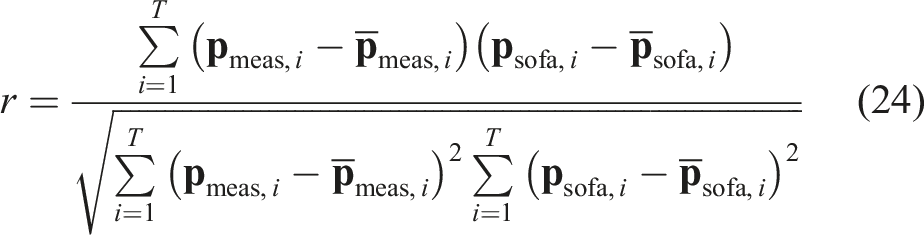
Portable Real2Sim2Real: Continuously change cases
Related results can be found in Movie S2, and its snapshots are shown in Figure 15. A total of five sequential Tool Center Points (TCPs) for the Panda arm were assigned to realize repeatable changing motion. In addition, the observed sim2real delay necessitates a low-speed portable motion. Therefore, we set the Panda arm’s linear velocity as 1% of its maximum Cartesian velocity limits. We applied our gravity-aware framework to a portable soft slender robot mounted on a moving robot arm. The robot arm performs two repeated sequential motions (each lasts for 90 seconds) defined by five TCPs. In (a), the soft robot maintains a straight configuration and achieves a straighter pose compared to the configuration without our method, as shown in (b). In (c), the soft robot demonstrates a 30-degree bend, with the measured results shown in (d). Note that the results in (b) and (d) are relative to the reference frame from the optical tracker at fixed positions.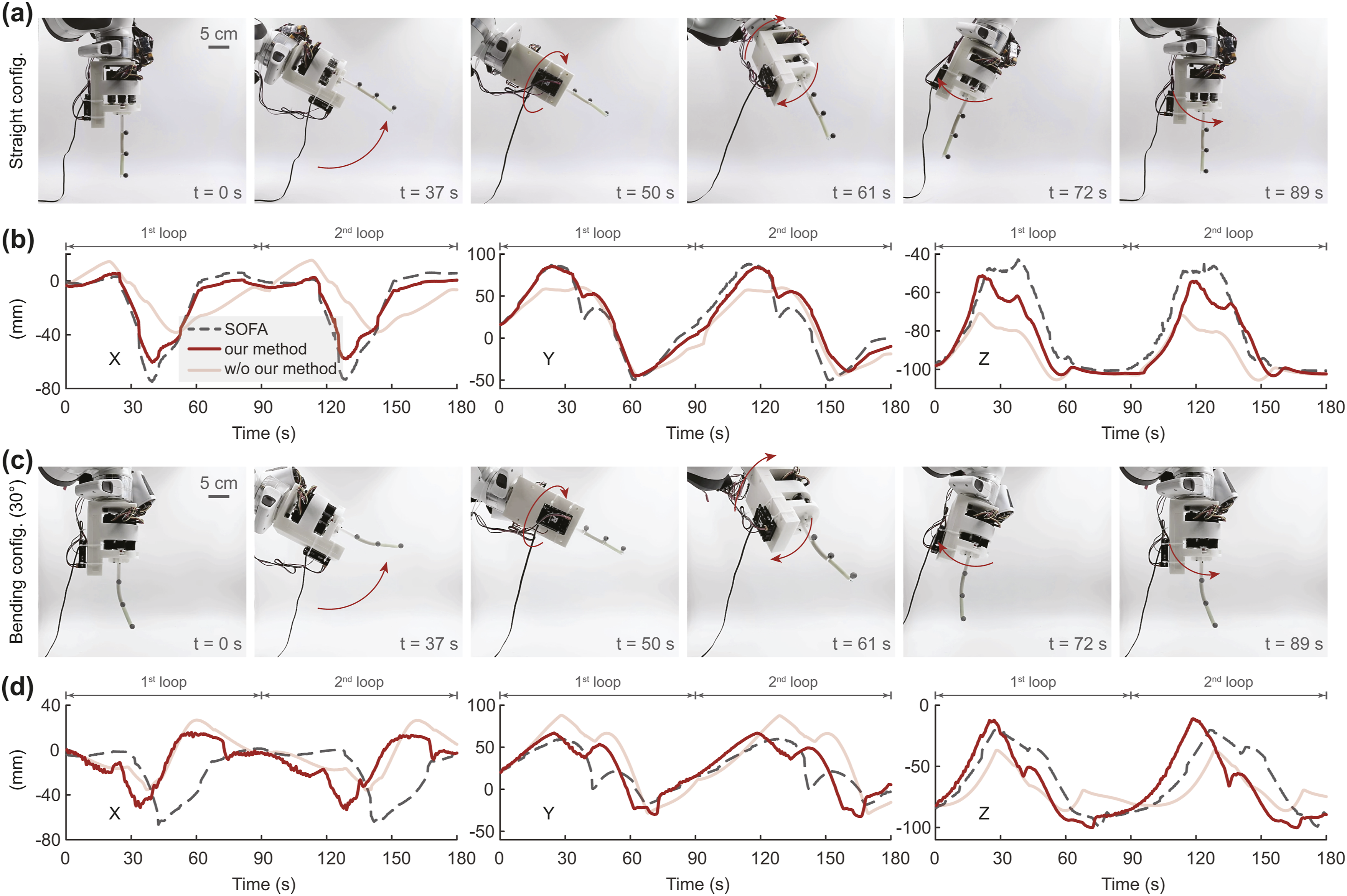
Robot arm held
To further evaluate the framework’s performance, we tested it in cases where the system’s spatial poses are continuously changed enabled by a robot arm. In the experiment, our portable soft robotic system was mounted on a Panda arm (Franka Emika GmbH, Germany). The Panda arm was teleoperated to change the 3D pose of its end-effector (viz., our soft robotic system), and such alteration was unknown to the simulation, as the simulation only reads from the embedded IMU. Since the EM sensors’ wiring may affect the soft robot’s deformation due to the large-scale motion, we switched to position-only optical tracking (FusionTrack 250, Atracsys LLC, Switzerland). The setup can be seen in Figure 16. Experiment setup for the portable real2sim2real cases where the soft robot undergoes continuous overall pose changes in 3D space.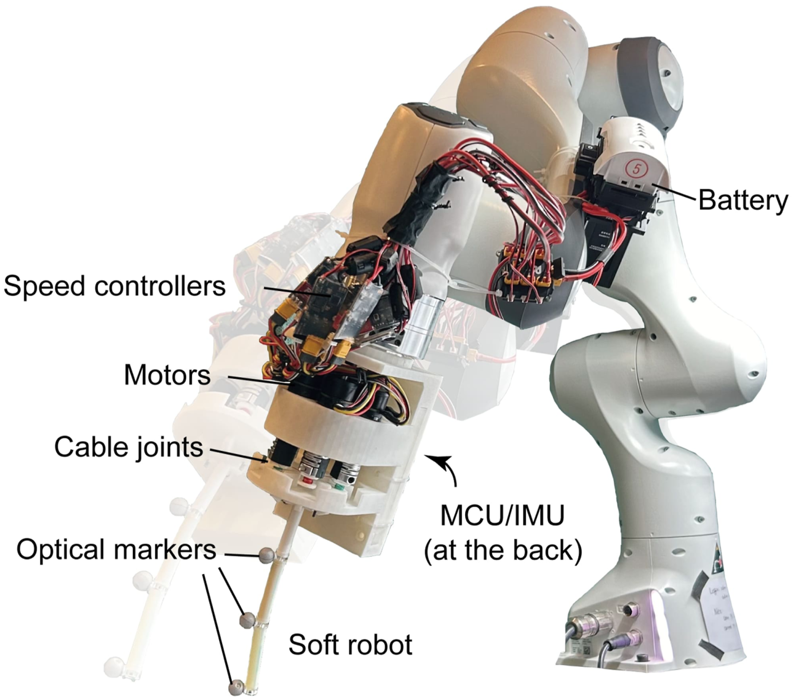
The results in Figure 15 verify our hypothesis and the effectiveness of our proposed framework. Regardless of the soft robot configurations (straight or bent) and the overall system configurations, the soft robot can be self-adjusted against gravity-induced undesired deformation as guided by the real-time simulation. Figures 15(c) and (d) show the soft robot’s tip positions (w.r.t. a stationary optical tracker). The results present a significant improvement in recovering the compensation strategy from the simulation, compared to the cases without amending any joint space motion compensation. Again, we use the sample Pearson correlation coefficient r to quantify the correlation between the measured and simulated data over time. The correlation coefficient for 0° as shown in Figure 15(a) and 30° as shown in Figure 15(c), improves from 0.9653 to 0.9830, and from 0.9394 to 0.9439, respectively.
Hand held
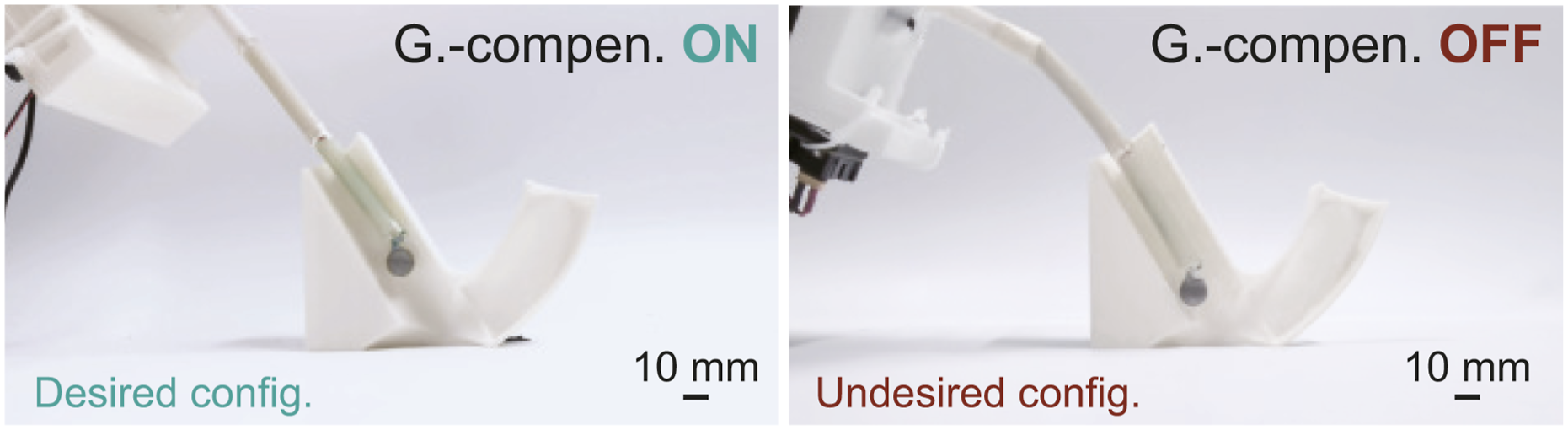
We conducted experiments to validate the applicability of our proposed method for soft slender robots in portable scenarios. The setup involved a cross-sectional two-way lumen phantom with a spherical object positioned deep within the lumen, accessible by the robot through the leaned lumens on both sides (see Figure 17). Note that the left lumen is straight, while the right one is curved. In the experiment, a volunteer was asked to hold the robot in one hand and retrieve the BluTack-glued spherical object through the lumen. Due to the long slopes of the lumens, our 100-mm long soft robot, without the proposed real2sim2real method, risked getting stuck and colliding with the lumen wall due to gravity-induced deformation. As shown in Figure 17(a) and in Movie S3, our method enables the handheld robot to reach the target object despite the slopes. This is achieved through real-time gravity awareness and autonomous configuration adjustment, facilitated by a single onboard IMU and our proposed framework. A comparison on straight configuration of the portable robot operating with and without the proposed gravity compensation method is shown in Figure 18. The results suggest that our method can be applied to handheld soft slender robots without manual task/joint space motion control. Our online real2sim2real framework allows a 6-DOF soft robot to perform arbitrary handheld tasks and can be, apparently, extended to a wider range of soft robots with a high aspect ratio and high DOF in the joint space. Possible applications include gastroscopy for patients in various postures and industrial endoscopy. Portable experiment—A volunteer was asked to hold the robot in one hand and retrieve the BluTack-glued spherical object (positioned inside the two-way phantom) through the sloped lumen. (a) The leaning lumen is straight and requires the robot to be straight. (b) The leaning lumen is curved and requires the robot to maintain the same curve shape throughout the object retrieval process. Comparison on straight configuration of the portable robot operating with and without the proposed gravity-aware proactive joint-level compensation strategy.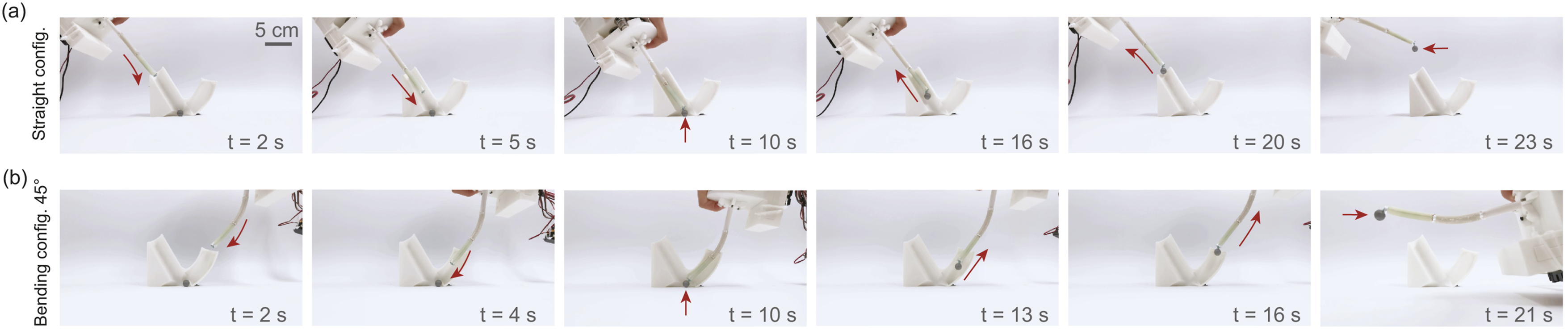
We extended our experiment to evaluate the applicability of the proposed method and system in medical settings. Prior studies have shown that altering patient posture during colonoscopy can enhance luminal distention and facilitate navigation (Wilson and Saunders, 2015). Although the left lateral (L) decubitus position is conventionally used, alternative orientations such as right lateral (R), prone (P), and supine (S) may offer additional advantages. A self-controlled colonoscopy robot capable of maintaining consistent performance across varying patient positions would therefore be highly beneficial. In our experimental setup, we employed a phantom colon embedded with a lesion model to simulate transrectal colonoscopy using the proposed hand-held robotic system and control framework. As illustrated in the experiment setup in Figure 19(a), an EM tracking system was used to record the robot tip position, while a micro-camera (OV6946, OmniVision) was inserted through the robot’s working channel to replicate standard endoscopic visualization. The phantom was positioned in both the supine (S, Figures 19(d)–(e)) and left lateral (L, Figures 19(e)–(f)) orientations. Prior to the procedure, an EM sensor was used to slide along the top, bottom, and lateral surfaces of the colon phantom to capture its external geometry in the form of positions relative to the transmitter frame. The results shown in Figures 19(b)–(c) illustrate the EM-tracked tip positions of the robot with and without the proposed gravity-aware joint-level compensation method. Without compensation, the robot gradually deviates from the intended shape and drifts toward the colon wall during insertion. In contrast, when the gravity-aware strategy is applied, the robot actively maintains the desired bent configuration, demonstrating improved stability and control. The results, presented in Figures 19(d)–(g) and Supplemental Movie S3, demonstrate that the robot maintained a stable configuration despite changes in body orientation and operator-induced perturbations. This stability enabled consistent visualization of the intracolon environment and lesion, underscoring the system’s robustness and potential for clinical application. Different body positions for colonoscopy. (a) A phantom colon with a lesion model was used to simulate transrectal colonoscopy with our hand-held soft robot and control framework. An EM sensor was used to measure the robot tip’s position. (b) Comparison between with and without implementing our gravity-aware (GA) joint-level compensation method in the supine position setting. The “patient” was positioned in (d–e) supine and (f–g) left lateral positions. Our method ensures consistent motion and stable imaging regardless of patient position and robot body orientation.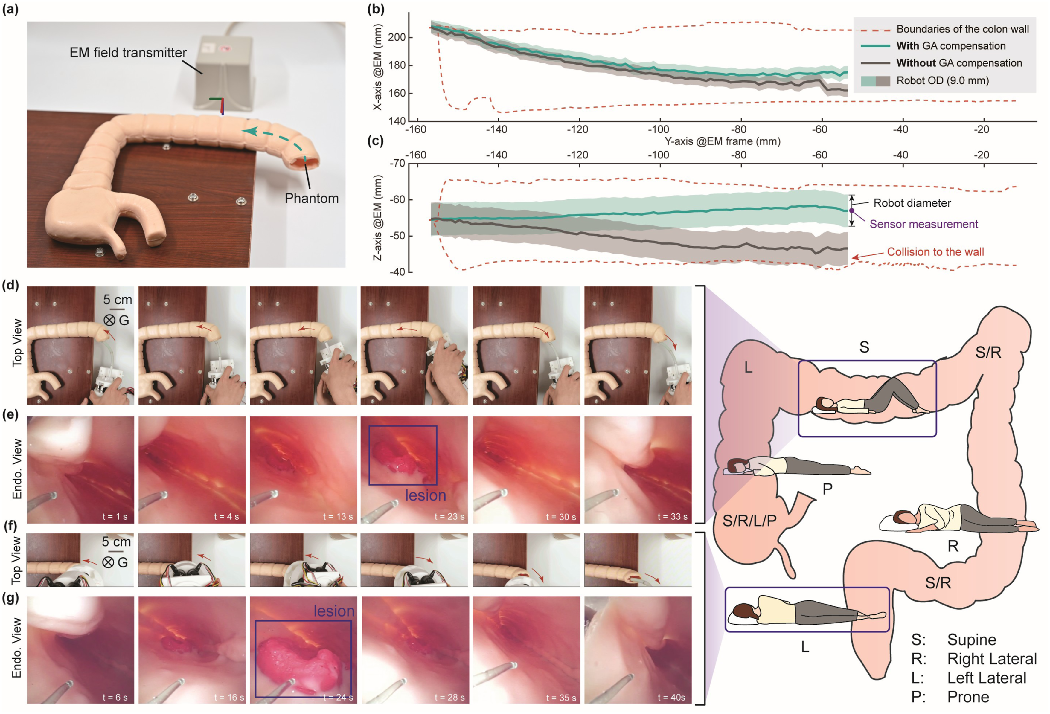
Discussion
Soft robots with gravity-aware capability and their compensation mechanisms 11.
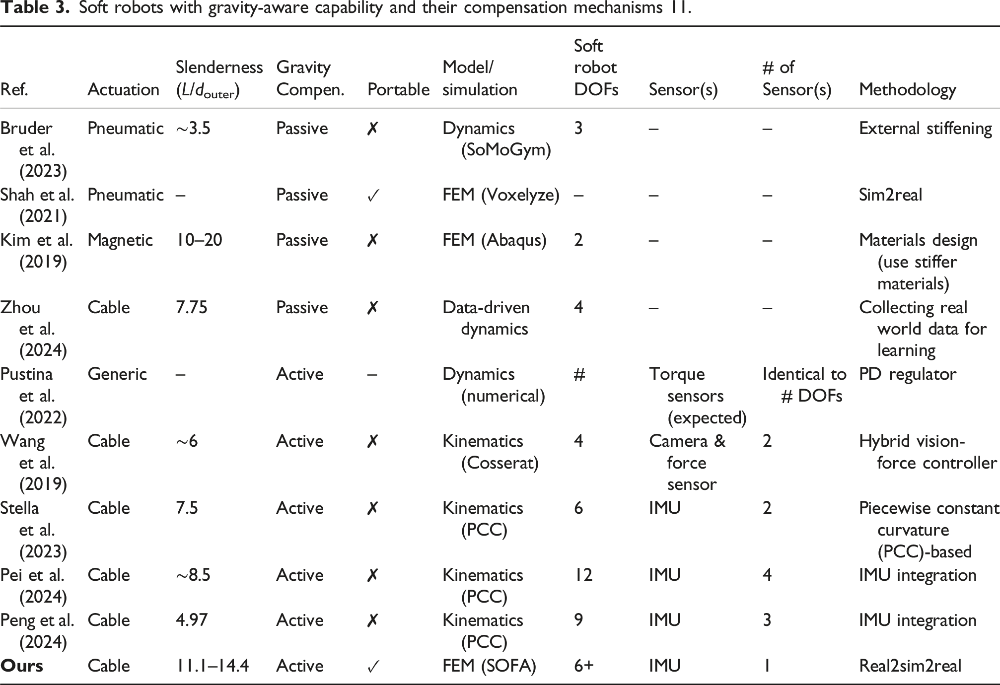
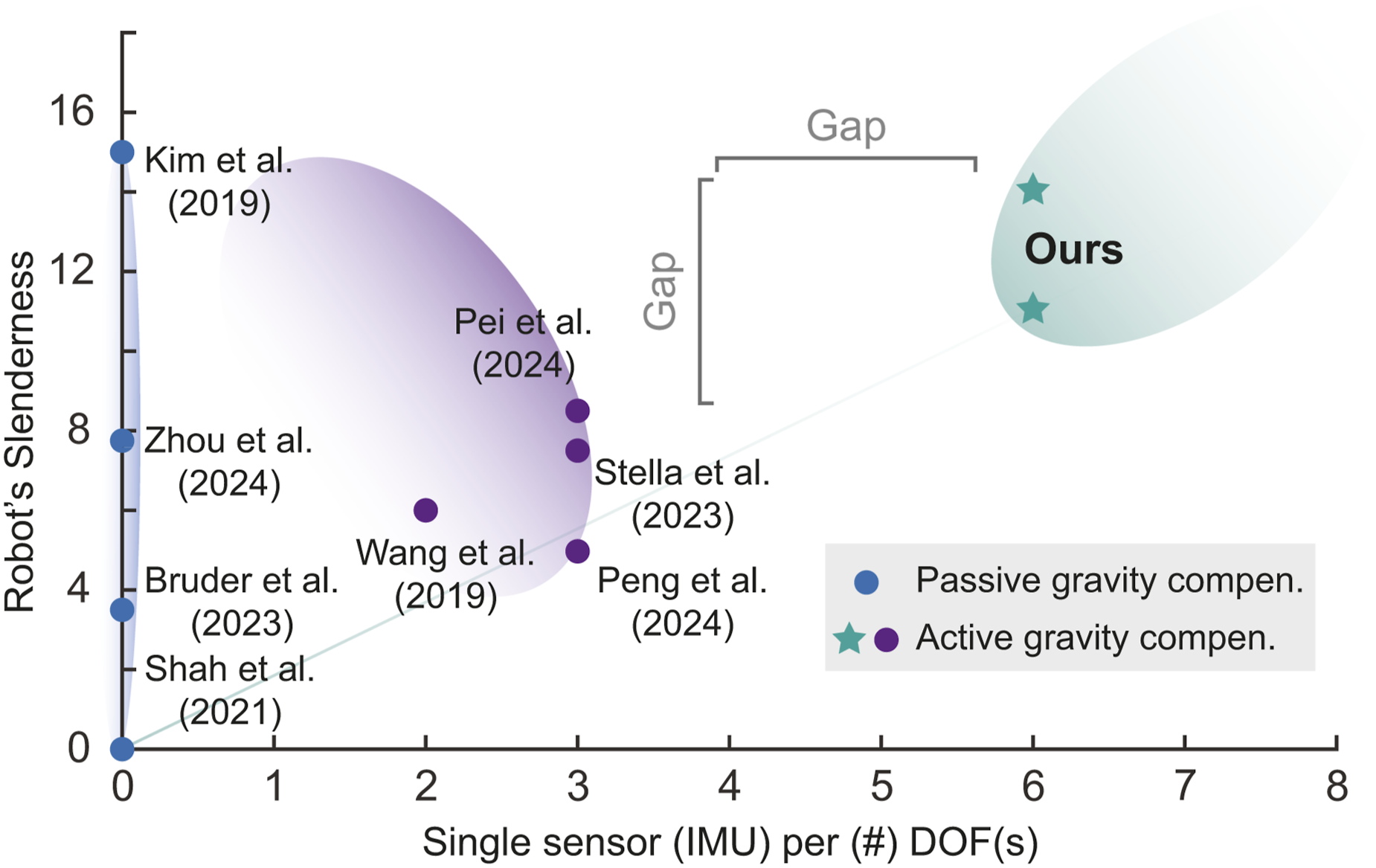
Comparing different state-of-the-art soft robots with gravity-aware capability and their compensation mechanisms based on the number of DOF(s) controlled by single sensor (IMU) and the robot’s slenderness.
Compared to other commonly used sensors for soft robots (such as fiber Bragg grating (FBG) sensors, optical/vision sensors, and EM sensors), IMUs are a relatively cost-effective option that require less installation complexity and sensor calibration. For instance, employing FBG sensors in a continuum robot requires delicate robot design to ensure sufficient internal space to accommodate the customized fragile optical fiber (Li et al., 2024), as well as the use of a laptop-sized FBG interrogator. If deformation is of interest, additional calibration using a mold with a fixed curvature is typically required for bending calibration (Hou et al., 2025). While soft waveguides are cost-effective and highly flexible, their practical implementation often requires extensive training using neural networks or a combination of numerical simulations and neural networks (Wang et al., 2024), which can hinder individual deployment and scalability. Electromagnetic tracking remains a widely adopted localization (also shape sensing (Shi et al., 2016)) technique in laboratory-based soft robots due to its non-line-of-sight capabilities and high spatial resolution. However, its deployment in slender robots often necessitates the integration of multiple tethered sensors along the body, which introduces practical limitations, including restricted maneuverability and reduced scalability, primarily due to the constrained effective workspace imposed by the EM field and the physical encumbrance of sensor wiring. In contrast, employing a single IMU in conjunction with a real2sim whole-body rendering approach simplifies system complexity while enhancing scalability.
Limitations fall in several aspects. For example, the current framework is constrained by the low-speed operation caused by the sim2real delay. However, it can be refrained by improving the computing resources. In addition, our method requires trial and error on the model’s meshing (parameterization) in the simulation beforehand. The modeling can be quite arbitrary and affects the computed efficiency and efficacy, including the robot inverse. Last but not least, our method still requires online computation with an external PC, while some applications would much benefit from a completed embedded system. Future work in offline virtual training on control policy can be explored.
Conclusions
This paper presents a real2sim2real framework designed to enable real-time gravity awareness and proactive joint-level compensation for portable cable-driven soft slender robots, ensuring they maintain the desired configuration. The core concept of the proposed framework is to leverage advanced soft body simulation to minimize the reliance on physical sensors. The framework leverages (1) real-world feedback from a single IMU attached to the robot’s base and (2) virtual-world inverse computation using a reduced-order FEM model of the soft robot imported into SOFA, facilitating closed-loop control in both real and virtual unified environments. We conducted controlled and demonstrative experiments to validate the hypothesis and assess the framework’s performance on a two-segment cable-driven soft robot. Our results indicate that a single IMU with temperature and drift filters is sufficient to reconstruct a real2sim-based soft robot under dynamic gravity conditions in SOFA, outperforming a commercial FEM simulator with controlled parameters and a simplified mechanics model. We verified our method’s efficacy, achieving a compensation recovery rate (correlation coefficient) of over 99% in static cases and 94% in dynamic cases. Additionally, we observed a time delay of approximately 3 seconds in the sim2real online deployment, which can be mitigated with a more powerful computational setup. Future work could explore external force interaction within the real2sim2real framework by incorporating additional virtualizable sensors.
Supplemental material
Supplemental material - Gravity-aware proactive joint-level compensation for portable soft slender robots using a single IMU and real-time simulation
Supplemental material for Gravity-aware proactive joint-level compensation for portable soft slender robots using a single IMU and real-time simulation by Jiewen Lai, Tian-Ao Ren, Pengfei Ye, Yanjun Liu, Jingyao Sun, Hongliang Ren in The International Journal of Robotics Research.
Footnotes
Funding
The authors disclosed receipt of the following financial support for the research, authorship, and/or publication of this article: Guangdong Basic and Applied Basic Research Foundation (Grant No. 2025A1515011594); National Natural Science Foundation of China (Grant No. 62403402); NSFC Distinguished Young Scientists Fund – Category A (Grant No. T252500134); Hong Kong Research Grants Council (Grant Nos. C4026-21GF, R4020-22, 14200425, 14206125, 14204524, 14203323, 14216022).
Declaration of conflicting interests
The authors declared no potential conflicts of interest with respect to the research, authorship, and/or publication of this article.
Supplemental material
Supplemental material for this article is available online.
Note
Appendix
References
Supplementary Material
Please find the following supplemental material available below.
For Open Access articles published under a Creative Commons License, all supplemental material carries the same license as the article it is associated with.
For non-Open Access articles published, all supplemental material carries a non-exclusive license, and permission requests for re-use of supplemental material or any part of supplemental material shall be sent directly to the copyright owner as specified in the copyright notice associated with the article.