
Abstract
In the last decades, supernumerary robotic limbs (SRLs) have been proposed as technological aids for rehabilitation, assistance, and functional augmentation. Whether they are in the form of wearable devices or grounded systems, SRLs can be used to compensate for lost motor functions in patients with disabilities, as well as to augment the human sensorimotor capabilities. By using SRLs, users gain the ability to perform a wide range of complex tasks that may otherwise be challenging or even impossible with their natural limbs. Designing effective strategies and policies for the control and operation of SRLs represents a substantial challenge in their development. A key aspect that remains insufficiently addressed is the formulation of successful and intuitive augmentation policies that do not hinder the functionality of a person’s natural limbs. This work introduces an innovative strategy based on the exploitation of the redundancy of the human kinematic chain involved in a task for commanding SRLs having one degree of freedom. This concept is summarized in the definition of the Intrinsic Kinematic Null Space (IKNS). The newly developed procedure encompasses a real-time analysis of body motion and a subsequent computation of the control signal for SRLs based on the IKNS for single-arm tasks. What sets our approach apart is its explicit emphasis on incorporating user-specific biomechanical and physiological characteristics and constraints. This ensures an efficient and intuitive approach to commanding SRLs, tailored to the individual user’s needs. Towards a complete evaluation of the proposed system, we studied the users’ capability of exploiting the IKNS both in virtual and real environments. Obtained results demonstrated that the exploitation of the Intrinsic Kinematic Null Space allows to perform complex tasks involving both biological and artificial limbs, and that practice improves the ability to accurately manage the coordination of human and supernumerary artificial limbs.
1. Introduction
Supernumerary robotic limbs (SRLs) offer the possibility to augment human capabilities in terms of perception and manipulation abilities (Eden et al., 2022; Prattichizzo et al., 2021), allowing individuals to perform complex sensorimotor tasks by coordinating biological and artificial limbs. Differently from prostheses and exoskeletons (Bao et al., 2019), which are designed to empower human natural movements, SRLs represent additional degrees of freedom (DoFs) that need to be controlled independently from and simultaneously with biological limbs. Moreover, when SRLs are adopted as artificial aids for assistance, rehabilitation, and functional augmentation purposes, ease of use and ease of learning become crucial. Such ease should be recognizable under several aspects, ranging from the intuitiveness of the control strategy to the users’ autonomy while using the augmentative devices. For instance, enhancing independency in patients suffering from motor disorders and impairments is fundamental to improve their quality of life.
The cutting-edge component to implement the idea of augmentation is the design of wearable sensorimotor interfaces. From a broad perspective, these interfaces are meant for establishing a bidirectional connection between the human sensorimotor system and the robot’s system of actuators and sensors. Through this connection, reciprocal awareness, trustworthiness, and mutual understanding are intended to be achieved, enhancing the overall integration between the user and the SRLs. For instance, by capturing signals from human body motion or muscle activation, the sensorimotor interfaces can leverage the redundancy of the human sensorimotor system to map commands for the robot limbs.
The research done in the last decades in augmentative and assistive robotics has been developing SRLs with different usages (fingers, hands, arms, legs), actuation systems (fully actuated, underactuated), and design features (rigid/soft materials, level of anthropomorphism, etc.). Besides the complexity of designing light and portable mechanical structures, it is important to consider the interaction between the robot and the human. Since the final aim of SRLs is to augment the manipulation or locomotion capabilities of humans, control signals from the human to the robot have to be acquired without interfering with the biological limbs.
To take a significant stride towards realizing this ambitious scenario, our work presents a novel methodology to extract a signal from the human kinematic redundancy for enabling the simultaneous control of natural and artificial limbs during task execution. Here, by kinematic redundancy we refer to body motions that do not affect the action of the biological hands. While, regarding muscular redundancy, that is, muscle activation patterns that do not generate net joint torques (e.g., the co-contraction of two antagonistic muscles, which counterbalance the effect of each other), results are already available in Gurgone et al. (2022).
From the user’s perspective, control strategies can be distinguished as autonomous and non-autonomous. In this work, the term non-autonomous will be used to mean an intentional and dedicated command which requires precise instructions from the user. As an example, a stroke patient with an impaired upper limb can activate an extra-finger through a push button placed on a ring worn on the healthy hand (Hussain et al., 2017). On the contrary, the term autonomous will be used to describe a control law which is able to adapt the system functioning to the user’s will without receiving specific instructions. This is usually represented by a control signal associated to an action which is not clearly distinguishable from those required by the ongoing task. For instance, an extra-leg supporting the wearer’s gait should follow the intention of walking without waiting for specific instructions on when to make a step.
As this paper aims at introducing a novel approach to non-autonomous control for SRLs, in the next section, we overview the state of the art focusing on techniques adopted to control SRLs in a non-autonomous way.
2. Related work
One of the first examples of SRLs dates back to 1981, when Stelarc built the Third Hand, a supernumerary five-finger robotic hand activated by abdominal and leg muscles (Kac, 1997). This wearable robot was primarily designed for artistic performances and lacked practical utility in augmenting human functional capabilities. Building upon that initial work, the development of supernumerary robotic limbs has been an ongoing, decades-long effort.
Taking into account more recent literature, Prattichizzo et al. (2014) presented the Sixth Finger, a modular extra-finger that can be worn on the wrist. While the mechanical design of the prototype has remained quite similar, several control strategies have been exploited in the last few years. As a first approach, a dataglove was used to capture the motion of the human hand, which was mapped in the motion of the extra-finger. In Hussain et al. (2015), the device flexion/extension was regulated through a wearable switch embedded in a ring, while in Franco et al. (2021), the authors presented a manually actuated version of Sixth Finger, featuring a ratchet system. The latter can be rotated using the contralateral hand to wind a tendon running through the finger, thereby flexing the entire structure. In Abdi et al. (2016), the authors presented a three-handed manipulation paradigm using the motion of a foot to control a third hand in a simple task. Similarly, in Kojima et al. (2017), the foot was selected as a preferred location for moving a robotic arm, while Kieliba et al. (2021) controlled a third robotic thumb using a toe. In Nguyen et al. (2019), the authors controlled their wearable SRL using three different control strategies based on three sensing setups, namely, an analog joystick, an IMU mounted on the dorsal side of a glove, and two surface electromyography sensors placed on one bicep muscle.
Most of these results highlight an implicit compromise in the strategies selected to control an SRL. Subjects can acquire new capabilities thanks to the supernumerary robotic limbs, but the dexterity of their limb is reduced by the need to command the robot. Similarly, the achievement of functional augmentation comes with a trade-off, potentially affecting other functionalities. Hence, this literature review raises an important research question: can humans learn to operate a supernumerary robotic limb collaboratively with their biological limbs, without restricting other physical abilities? To successfully achieve robotic body augmentation, we need to ensure that, by giving a user an extra artificial limb, we are not trading off the performance of the task.
A few approaches for functional augmentation based on these concepts have been recently investigated. An example is in Salvietti et al. (2016), where surface electrodes placed on the user’s frontalis muscle allowed to capture an electromyography signal to activate the Sixth Finger motion. A more complex system involving electroencephalography (EEG) was evaluated by Penaloza and Nishio (2018). The authors proposed an interface based on EEG for controlling an SRL that can be activated when the human operator imagines a grasping action. In Lisini Baldi et al. (2017), the motion of an assistive robotic arm was controlled through a human–machine interface based on a combination of head tilt estimation and electromyography signals. Dominijanni et al. (2023) proposed a human–machine interface that integrates the user’s gaze and diaphragmatic respiration to control the orientation and movement of the extra arm. In their work, diaphragmatic respiration modulation is decoded in three states, with diaphragm expansion corresponding to a forward movement of the extra arm, diaphragm contraction corresponding to a backward movement, and relaxation corresponding to rest. To control the extra arm, users had to gaze at a given target appearing in the virtual environment to select it and then could control the movement toward the target (or away from it) by expanding (or contracting) their diaphragm beyond a given threshold.
Despite the aforementioned control approaches not hindering other users’ functions, they involve motions of body parts not directly implicated in the motor task, thus requiring further resources from the user. Moreover, such body parts may be required for other concurrent tasks in most application scenarios, and not be available for SLR control. For example, the motion of the foot to control an SRL may be used if the user is sitting but unavailable if the user is standing or walking. Finally, the majority of control approaches operate on a discrete control basis, lacking fine control over the robot.
In this context, the goal of this research is to introduce a new control paradigm highly focused on users and their tasks. The underlying idea is to exploit the redundancy of the human musculoskeletal system to control extra degrees of freedom. To understand the potential of this approach, the wide range of movements that can be performed to complete the same task has to be considered. This redundancy is not surprising considering the complexity of the human body: Zatsiorsky (1998) estimated that there are 148 movable bones and 147 joints in the human body, which represent 244 degrees of freedom, a huge number compared with the DoFs required for ordinary tasks. Even considering a simple model of the upper limb with 7 DoFs, position and orientation of the hand (6 DoFs) can be maintained by different limb postures. Despite this, many control interfaces for robotic devices take advantage of functional DoFs rather than redundant DoFs. One plausible rationale for this prevalent design choice stems from our limited awareness of redundancy. In practice, we execute movements for a specific task based on what intuitively feels most natural, without thoroughly analyzing all potential kinematic configurations. Moreover, when developing human–machine interfaces, engineers tend to search for standard design guidelines to match the requirements of a wide range of users. On the contrary, the available degrees of freedom change according to the user and the task. Thus, only an accurate a priori evaluation of the user–task pair (e.g., user’s motor features) can provide parameters to properly calibrate a control interface based on the kinematic redundancy.
3. Motivation and contribution
The motivation for this study arises from the inherent constraints associated with controlling supernumerary robotic limbs using motions of body parts not directly involved in the motor task at hand. For instance, all control policies relying on inputs from the lower limbs to manage SRLs assisting in manipulation tasks inevitably restrict the user’s freedom to stand stably or to walk during task execution. Beyond the need to stand or walk during the task, there exist numerous daily life scenarios where allocating a biological upper limb for SRL control proves impractical. Consider, for instance, the multitude of situations in which we perform two unimanual tasks simultaneously, essential for optimizing our daily routines, or the many bimanual tasks in which we rely on the coordinated motion of both upper limbs. Examples of simultaneous bimanual tasks range from using a phone with one hand while writing on a paper with the other to culinary activities such as stirring ingredients in a bowl while simultaneously pouring or measuring others. Examples of bimanual tasks include manipulating large objects (e.g., boxes), holding bread with one hand while cutting a slice with the other, pushing a shopping cart while grocery shopping, or folding a shirt.
In these scenarios, using body parts not directly involved in the ongoing task(s) for SRL control is not possible without sacrificing other essential actions, thus reducing the users’ capability. This implication contradicts the very idea of human augmentation, particularly for individuals with reduced mobility who rely on SRLs to restore lost functionalities rather than replace useful abilities.
This is the reason why, in this work, we want to evaluate the feasibility, the limits, and the potentialities of using motions of body parts already involved in the ongoing task to control a 1-DoF SRL. Our premise is that control based on additional body parts’ motions offers superior performance, being inherently simpler and more established compared to relying solely on motions of already involved body parts. Therefore, with the proposed technique we do not expect to outperform that methodology, but rather to assess the extent to which our approach diverges from it.
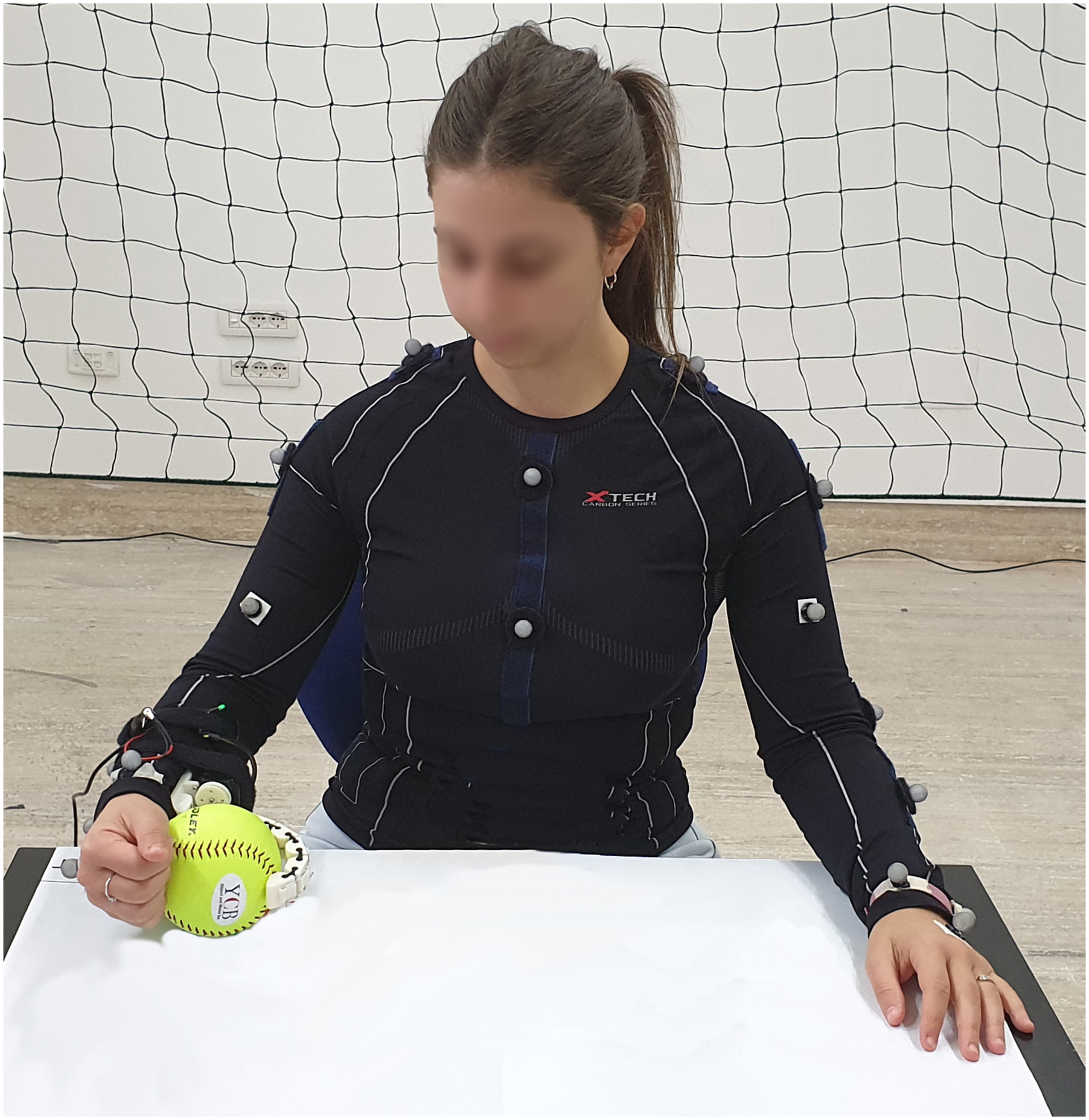
To put it briefly, the contributions of this work can be listed as follows: • a novel methodology for computing the Intrinsic Kinematic Null Space for seamless integration of SRLs into human activities. The concept is visually represented in Figure 1, in which a user is controlling an extra-finger through the proposed control paradigm; • a systematic and quantitative assessment of performance that comprises an evaluation conducted within a common framework designed for measuring the enhancement capabilities of a specific SRL Human–Machine Interface (HMI) implementation and for comparing various implementations in the field of human augmentation; • a preliminary comparison with other HMIs, namely, Intrinsic Muscular Null Space and Extrinsic Kinematic Null Space. A user exploiting her Intrinsic Kinematic Null Space for controlling the opening/closing mechanism of a wearable robotic extra-finger in an augmented manipulation task. The task requires the involvement of natural (i.e., the right arm) and artificial (i.e., the robotic extra-finger) limbs to pick and place objects.
In what follows, we start providing the definition of the proposed control paradigm based on the exploitation of the Intrinsic Kinematic Null Space. Then, we introduce the experimental campaign designed to assess the performance of participants in simultaneously controlling natural and extra DoFs.
In particular, the first experiment aimed at verifying whether the Intrinsic Kinematic Null Space can be used to command an extra degree of freedom to perform dual tasks. Then, with the second experiment, we performed a detailed analysis of how the users’ control ability is affected by the difficulty of the task and how fast performance improves with practice.
Once the capability of the control paradigm was assessed, we conducted further experiments to examine its exploitability in a real-world environment. In Experiment 3, subjects were asked to control a wearable SRL while performing dual tasks related to activities of daily living. Following that, in Experiment 4, the focus shifted to controlling a grounded SRL while engaging in similar dual-task scenarios. Finally, limitations, conclusions and directions for possible future work are drawn in the conclusive Sections.
To the best of our knowledge, this represents the first attempt to investigate the feasibility and usability of this novel control strategy for human–device interaction.
4. Intrinsic kinematic null space
4.1. Definition
The main novelty introduced with this work concerns the concept of Intrinsic Kinematic Null Space.
According to the definition of kinematic null space in robotics, the redundancy of the human body, that is, the fact that there are more degrees of freedom than those required for a certain task, is exploited to command an additional degree of freedom.
Adapting the concept of kinematic null space to the human body is not a straightforward operation: differently from a serial robotic manipulator, humans have more than one end-effector (e.g., hands and foots) and can perform multiple tasks at the same time. Thus, for identifying the exploitable degrees of freedom, it is necessary to specify which is the considered end-effector and, consequently, the task we refer to.
From this perspective, considering a task to be accomplished and the kinematic space of the whole body, we can make a distinction between two types of null space: Extrinsic Kinematic Null Space (EKNS) that refers to velocities of joints which are not involved in such a task; Intrinsic Kinematic Null Space (IKNS) that refers to velocities of joints directly employed in the task.
For instance, grabbing a box with two hands involves joints of shoulders, upper arms, forearms, and wrists. Motions of all the other joints (e.g., knees and ankles) are in the Extrinsic Kinematic Null Space. On the contrary, the motion of the joints of shoulders, upper arms, forearms, and wrists which does not generate velocities of the hand belongs to the Intrinsic Kinematic Null Space.
Bearing in mind the control of SRLs, movements in the EKNS may be easier to identify, and thus to be extracted and associated to the device control. However, their exploitation would limit users’ mobility by demanding the involvement of further joints beyond those required for the task execution. As mentioned in Section Introduction, taking advantage of movements in the Intrinsic Kinematic Null Space lets the user operate a device using body parts already involved in the task, without compromising the use of free limbs which instead may be involved in further parallel tasks.
In this work, we focused our attention on exploiting motions in the IKNS in the specific use case of controlling a SRL while performing single-arm tasks, since we identified them as critical for impaired people and the most paradigmatic for presenting this innovative approach. To identify the IKNS in a simple single-arm task, the following procedure was adopted.
4.2. Computation
While in robotics computing the null space of a given kinematic chain is a straightforward operation, this estimation is more challenging when applied to humans. The problem stems from the lack of simple kinematic models incorporating the wide range of constraints each human body can be subjected to. Besides the anatomy of the human musculoskeletal system, ages, habits, and motor skills strongly influence the way people interact with objects and the surrounding, with the outcome that each individual is prone to perform the same task in a different way.
To overcome this problem, we developed a user-centred, data-driven, systematic procedure to identify the IKNS. An overview of the method is shown in the block scheme depicted in Figure 2. The first step to take before computing the IKNS is that of identifying the kinematic chain to be analyzed. Then, data acquired from the identified joints will be used to compute the IKNS. Flowchart reporting the phases for computing the control signal. The process starts with a preparatory phase in which the kinematic chain is identified accordingly with the task and N points are selected for exploring the range of IKNS motions. Then, the ‘Data Collection and Clustering’ phase considers the data acquired during the motions and outputs the direction (Z), the minimum (m), and maximum (M) values for each cluster.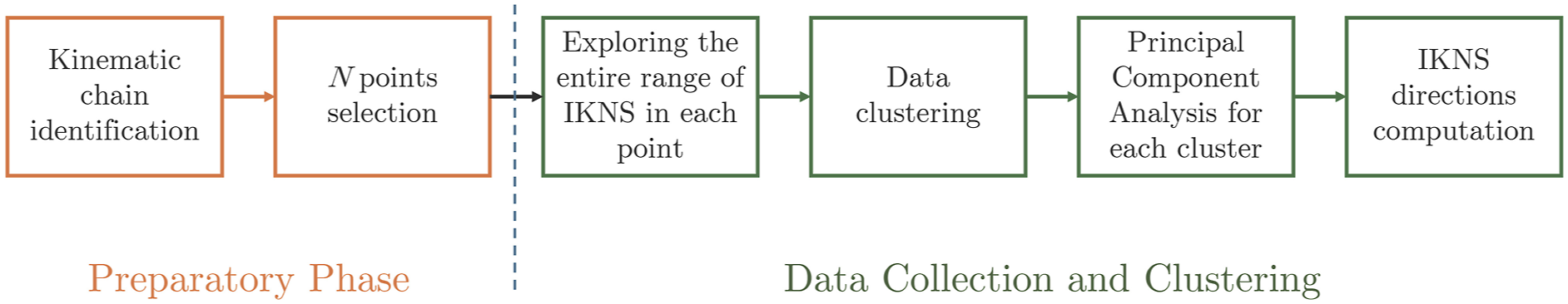
4.2.1. Kinematic chain identification
As stated in its definition, the IKNS is dependent on the performed task. For this reason, to estimate the current involved joints, it is fundamental to take into account some general knowledge on the morphology and the kinematic constraints of the human body to determine which joints are required to perform a certain task. In other words, the kinematic chain involved in the task needs to be a-priori identified. For instance, in this paper we consider a single-arm task, where the end-effector is the hand and consequently the significant chain is composed of the joints of shoulder, elbow, and wrist, and the associated links. Joint velocities that do not contribute to change the hand velocity are then considered belonging to the IKNS.
4.2.2. Data collection and clustering
To compute the IKNS of a certain person, their movements need to be recorded during the task execution and then analyzed. In particular, the pose and velocity of the end-effector of the selected kinematic chain and the velocity of its joints need to be estimated.
It is worth noting that the null space changes in accordance with the position of the end-effector, that is, it depends on the actual kinematic chain configuration. Hence, in theory it would be necessary to compute the null space for each point of the workspace. To avoid this physical burden for the users, we developed a procedure to automatically find the null space in any point of the user’s workspace given its value in a finite set of N points.
Let us now focus on the single-arm task considered in this paper. The N points correspond to 3D poses of the user’s hand and are chosen to cover the dexterous region of the arm workspace. Indeed, considering the entire available workspace is useless since at the boundaries the mobility of the considered body part is reduced. For instance, when the arm is fully extended (at the limit of the reachable workspace), it is not possible to impose an arbitrary motion to the arm without moving the hand.
In the data collection phase, the user is asked to execute the single-arm task in each of the N points while exploring the entire range of IKNS motions. At each time instant t, the velocity of the J DoFs of the selected kinematic chain is acquired and stored in
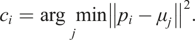
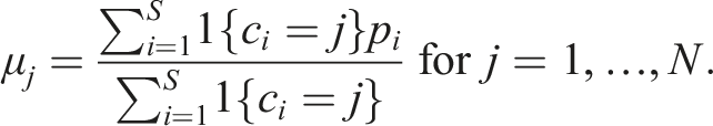
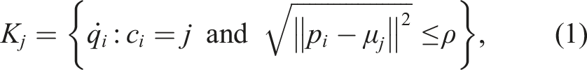
Data captured in the N points are clustered and separately analyzed. The algorithm is based on the k-means approach and implements the following steps: (1) Compute a minimal bounding box for the recorded hand poses Y using the algorithm proposed in Korsawe (2015). (2) Initialize the coordinates of the N centroids μ1, …, μ
N
. If N <8, that is, lower than the number of bounding box corners, starting centroids are randomly assigned to N corners; if 8 ≤ N <14, where 14 corresponds to the number of corners plus the number of faces of the bounding box, starting centroids are placed onto the corners and randomly assigned to the centre of N − 8 faces; if N = 14, starting centroids are assigned to all corners and centres of the faces; otherwise, if N >14, starting centroids are placed onto the corners, in the centres of the faces, and then randomly in each face. (3) For each point p
i
∈ Y, with i = 1, …, S, compute the Euclidean distance between p
i
and each centroid μ
k
, with k = 1, …, N, and assign p
i
to the cluster with the closest centroid by computing the label: (4) Compute the average of the observations in each cluster to obtain new centroid locations: (5) Repeat steps (3) through (5) until cluster assignments do not change, or the maximum number of iterations is reached. (6) For each cluster, consider only data
At this stage, the multidimensional space of the kinematic null space has to be projected in the extra degree of freedom space. This has to be done cluster-wise.
For each cluster j, firstly the acquired joint velocities are transformed through Principal Component Analysis (PCA) into a set of values of linearly uncorrelated variables called Principal Components (PCs). PCA is particularly effective in dealing with a large number of system variables. Secondly, depending on whether the percentage of data variation explained by the first principal component is at least 80% or not, either this one or the norm of the first two PCs can be taken as direction
Figure 2 illustrates the steps leading to the computation of the directions for the IKNS-based control signal, while Figure 3 depicts data collected and clustered in a representative trial with N = 10. In Figure 3(a), the trajectory performed by the user is reported. In Figure 3(b), the identified clusters are depicted and highlighted with blue spheres. Finally, the considered points for computing the cluster-wise PCA are shown in Figure 3(c). From data collection to workspace clustering in a representative trial. In (a), the trajectory depicted by the marker attached to the user’s right hand. In (b), clusters are represented by different colours, while the considered neighbourhood of the centroids is highlighted with blue spheres. In (c), only the data considered for the PCA are reported.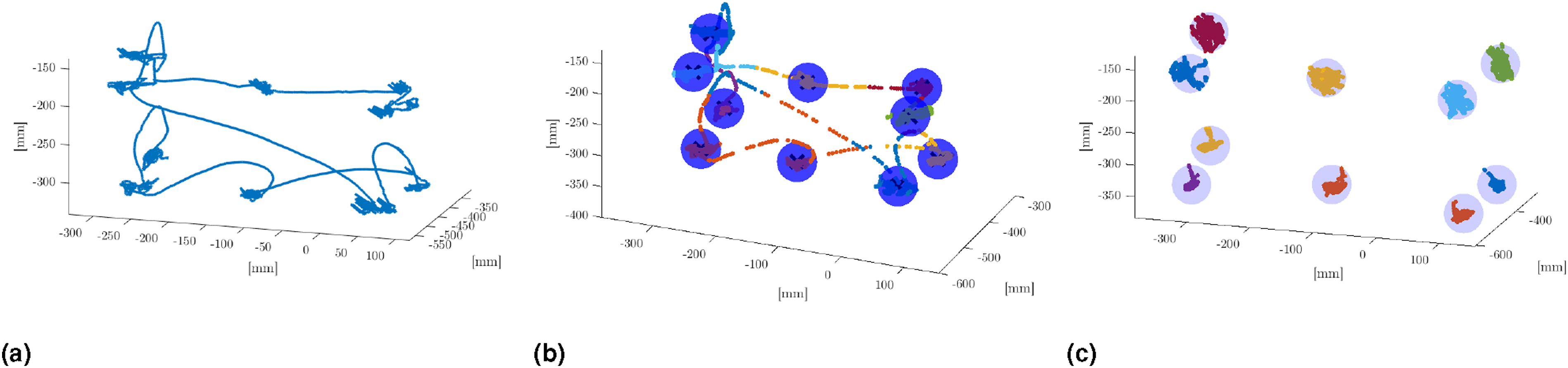
4.2.3. Online interpolation
As previously mentioned, the null space changes depending on the position of the hand with respect to the whole body. Thus, a fundamental requirement for the effective control of an extra DoF is the capability of computing the IKNS-based control signal in the whole user’s workspace in real time manner. In the proposed implementation, the algorithm exploits Z
j
, m
j
, and M
j
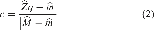
to compute online and seamless the value for controlling the SRL. A three-dimensional Delaunay triangulation-based natural neighbour interpolation (Cazals et al., 2004; Lee and Schachter, 1980) is used to reconstruct online the direction associated to the current null space as a smooth approximation of the directions of the nearest clusters. The Delaunay triangulation is an established method to define neighbourhood relations in multi-particle systems. In this way, it is possible to compute the control signal in any point of the working space, depending on the posture of the user. The control signal c is calculated as follows:
5. Experimental design
5.1. Methodology
The goal of the experiments presented in this paper was to assess whether the proposed system is effective for controlling an extra degree of freedom.
The experimental validation aimed at answering the following research questions: (i) Is it possible to use the IKNS to command an extra degree of freedom to execute dual tasks? (ii) How is the user control ability affected by practice considering the difficulty of the task? (iii) Is the IKNS-based control easy to learn for operating a wearable extra-finger to accomplish common activities of daily living requiring simultaneous tasks? (iv) How does user performance in accomplishing common activities of daily living that involve simultaneous tasks differ when using the IKNS-based control compared to an EKNS-based control?
Experiments were conducted both in virtual and real environments. A flow diagram of the experimental procedure is in Figure 4. Each user gave their written informed consent to participate and was able to discontinue participation at any time during the experiments. The experimental evaluation protocols followed the declaration of Helsinki, and there was no risk of harmful effects on participants’ health. Data were recorded in conformity with the European General Data Protection Regulation 2016/679, stored on local repositories with anonymized identities (i.e., User1 and User2), and used only for the post processing evaluation procedure. Flow diagram of the experimental procedure. Experiments conducted in the virtual environment (i.e., 1 and 2) are depicted in dark red, while experiments conducted in the real environment (i.e., 3 and 4) are depicted in light red. The number of trials is reported for each experiment and for each experimental condition.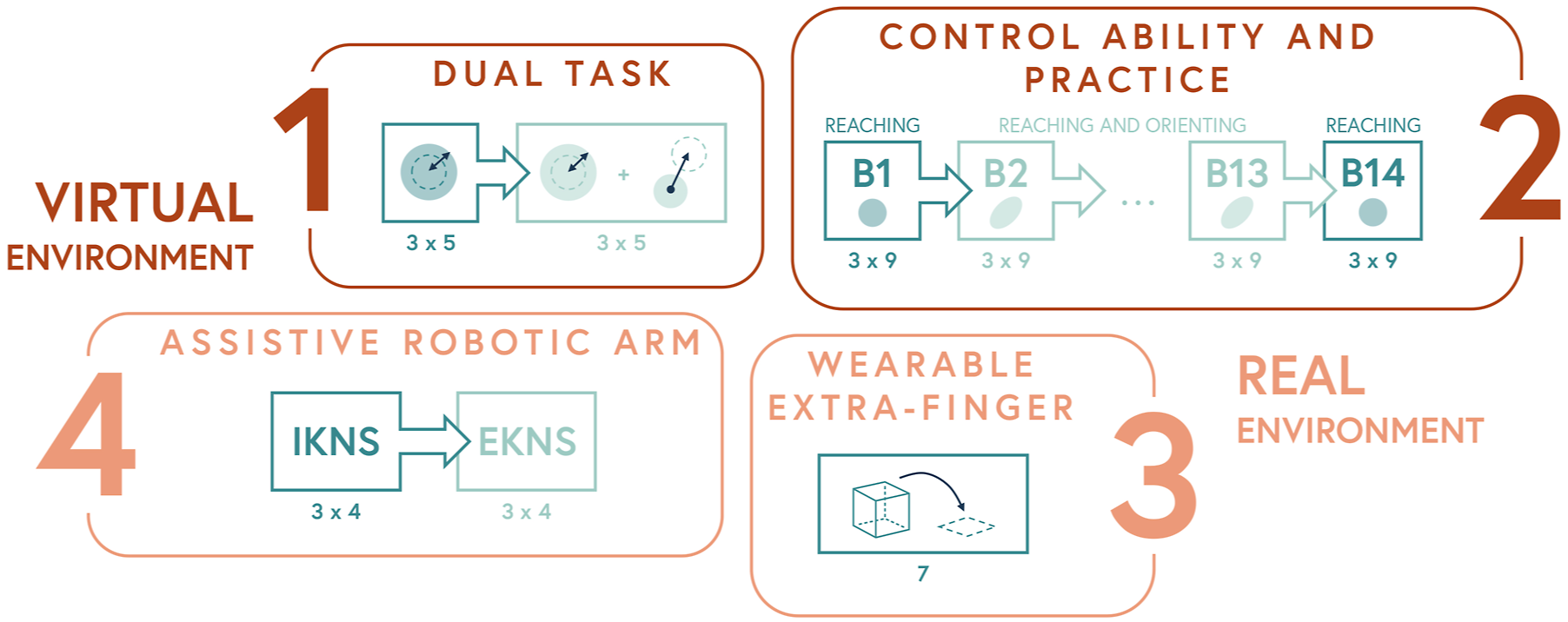
Overall, 38 subjects participated in the experimental campaign, ten in each of the first three experiments and eight in the fourth experiment. They were seven males and three females (from 22 to 57 years old, mean 35 ± 4.5, all righthanded) in the first experiment, five males and five females (from 25 to 43 years old, mean 31 ± 2.5, all right-handed) in the second experiment, six males and four females (from 21 to 55 years old, mean 28 ± 5.5, all right-handed) in the third one, and four males and four females (from 26 to 59 years old, mean 34 ± 10, all right-handed) in the fourth one, respectively. All of the participants were healthy subjects, and none of them had previous experiences in controlling supernumerary robotic limbs.
Every experimental session was preceded by a calibration procedure in which the IKNS of each subject was identified by applying the procedure described in the previous section.
All the experiments were performed in a room equipped with 10 Vicon Bonita cameras. To record arm joint angle values, retro-reflective markers were attached to the subject, who was located at the centre of the room. Eight cameras were placed at the upper corners (two per corner, with a different orientation), while the remaining two were fixed to tripods placed on opposite sides of the room, on the left and right side of the subject, respectively. The body posture was reconstructed online by means of Vicon Nexus 3.10 Software (Vicon Motion Systems Ltd, UK), with a frame rate of 100 Hz.
5.2. Calibration
5.2.1. Skeleton calibration
As a first step, 24 retro-reflective markers were attached to the subject in accordance with the Oxford Upper Body Model (Vicon Motion Systems Ltd UK, 2022), following the schematic illustration reported in Figure 5(a). To calibrate the system, each participant was asked to stand at the centre of the room for 5 s. A static acquisition and anthropometric measurements were used to create each user’s upper body skeleton model, consisting in 20 DoFs (as visually depicted in Figure 5(b)). An example of user-calibrated upper body skeleton is shown in Figure 5(c). (a) Vicon markers positioning in accordance with the Oxford Upper Body Model (Vicon Motion Systems Ltd UK, 2022), (b) the skeleton DoFs considered within this work, and (c) the kinematic model of a subject fitted online in a representative trial.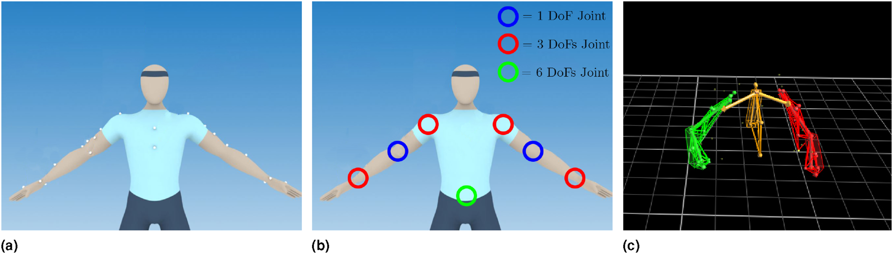
5.2.2. IKNS computation
Once the skeleton was modelled, a dedicated computer acquired images from the cameras. Thanks to the calibration procedure, the user’s skeleton was automatically reconstructed and the kinematic model was fitted online. This step enabled the real time capturing of joint angle values and body segments positions. To gain awareness of the workspace, participants were asked to seat and explore the arm workspace with the hand without moving the torso. After 1 minute of free exploration, participants were told to visualize an imaginary parallelepiped covering their arm dexterous workspace and to select 10 points that is eight in the proximity of the vertexes and two at the centres of the upper and lower surfaces. To avoid arm singularities, participants were suggested to exclude points on the boundaries of the arm workspace (i.e., where the arm is fully extended). Participants were instructed to place the hand in each of the selected points and freely move the arm for 5 seconds, holding the hand as steady as possible (i.e., without changing position and orientation). They were asked to explore the entire range of motion available in each position to record minimum and maximum reachable values.
Starting from the values recorded in the 10 calibration points (Figure 3(c)), the algorithm described in Section Intrinsic Kinematic Null Space can compute the control signal in the entire user’s surrounding. Thus, when the user performed movements in the IKNS, a software was in charge of computing the projection of the current joint values to the actual direction in real time, depending on the current hand position. The resulting value was then used to control the additional DoF required by the particular task under investigation. All subjects performed the experiments exploiting for each cluster only the first principal component as direction for generating the control signal.
6. Experiment 1 – dual task
6.1. Experiment description
In this experiment, we aimed at answering the first research question, that is, “Is it possible to use the IKNS to command an extra degree of freedom to execute dual tasks?” To this end, a virtual environment was developed and rendered using a Samsung HMD Odyssey (Samsung Electronics Co., Ltd.), as illustrated in Figure 6. (a) The user wearing retro-reflective markers. (b) The sphere controlled by the user (red sphere) overlapping the target sphere (green sphere) in the case of parallel tasks.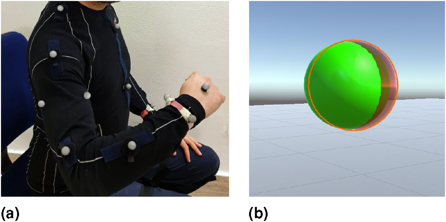
Participants were asked to seat and move their upper limb to control the position and the radius of a virtual sphere. The goal of the experiment was to overlap two spheres: one controlled by the user and one considered the target. Two different conditions were tested. In both conditions, subjects could change the radius through the IKNS-based control signal, which was mapped for the purpose in the range [0, 100] cm. In the first condition, the position of the target sphere was fixed, while in the second condition, the user had also to align with the position of the target sphere by moving the hand. In particular, the coordinates of the centre of the sphere corresponded to the coordinates of the marker positioned on the back of the right hand. In other words, in the second case two simultaneous tasks were required: the primary task was to align the centres of the two spheres and the secondary task was to adapt the radius of the controlled sphere to match the target dimension.
Each subject repeated the experiment twice, testing both the conditions proposed in a random order. For each condition, three trials corresponding to three different target positions were tested. For the ‘Dual Tasks’ condition, trials started displaying a tiny red sphere (indicating the current hand position) and an initial target sphere with 15 cm radius. This initial phase lasted 5 s and served to let the user align the spheres centres. Then, the radius of the goal sphere changed five times assuming random values in the range [10, 90] cm, once every 5 s. Differently, for the ‘Single Task’ condition, the position of the hand was not shown in the virtual environment (as the user could not control the position of the sphere), and the initial phase of 5 s served only the purpose of preparing the subject for the starting of the trial. Then, as in the other condition, the radius of the goal sphere changed five times in the range [10, 90] cm.
6.2. Metrics of interest
Errors in matching the radii (in both conditions) and in correctly positioning the centres of the spheres (only for the second condition) were considered as metrics of success in accomplishing the task. Therefore, performance in (i) maintaining the hand in a steady position and (ii) matching the spheres radius were measured by means of the Root Mean Square Error (RMSE). For the performance in maintaining the hand in a steady position, the considered error did not include the initial alignment. Similarly to Parietti and Asada (2017), for each trial t, we defined the RMSE as
6.3. Results and Discussion
The opportunity of performing multiple tasks with the same body part is one of the novelties presented in this work. Thus, answering to the question “Is it possible to use the IKNS to command an extra degree of freedom to execute dual tasks?” represents a key point for the overall evaluation. Additionally, considering the specific use case explored in this study, people controlling SRLs often require to simultaneously accomplish multiple tasks (such as grabbing a bottle and unscrewing the cap, stabilizing an apple and peeling it, etc.); therefore, the feasibility of associating the control interface to the natural limb involved in the task needs to be assessed. To this aim, we designed Experiment 1 to evaluate the user ability in carrying out two tasks at the same time, both involving the same kinematic chain.
For assessing the feasibility of using the IKNS-based control to fulfil an additional task, we compared the performance achieved in the aforementioned case with the performance obtained when using the IKNS was the only task required. This way, the first condition (the one with only the IKNS-based task) served as reference for evaluating the performance obtained when performing parallel tasks. Concerning the results of the second condition, if both the RMSEs on primary and secondary tasks are low and comparable, the proposed strategy is considered effective. On the contrary, an unbalanced performance output indicates that the IKNS-based approach is too demanding or not suitable for the purpose.
Results of Experiment 1.
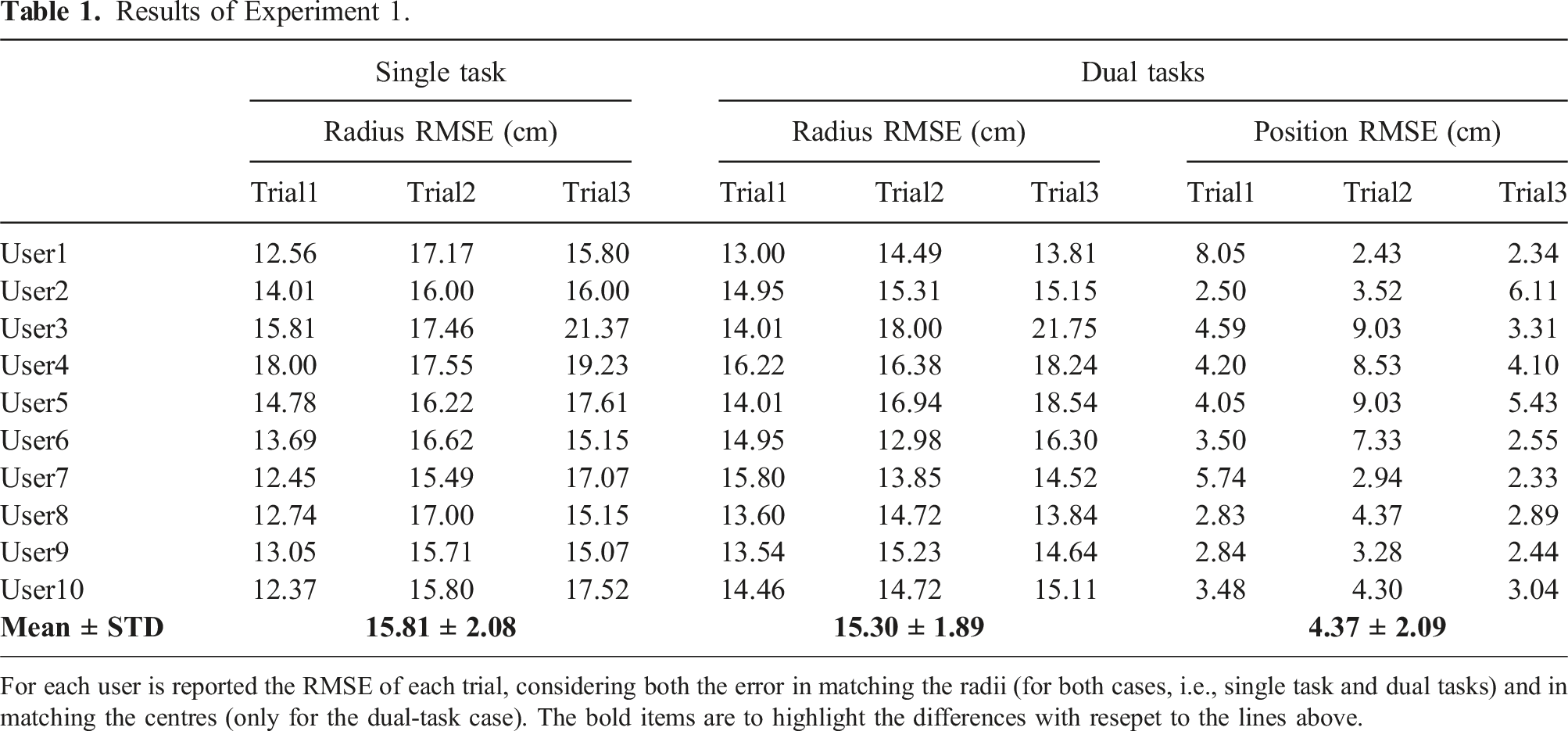
For each user is reported the RMSE of each trial, considering both the error in matching the radii (for both cases, i.e., single task and dual tasks) and in matching the centres (only for the dual-task case). The bold items are to highlight the differences with resepet to the lines above.
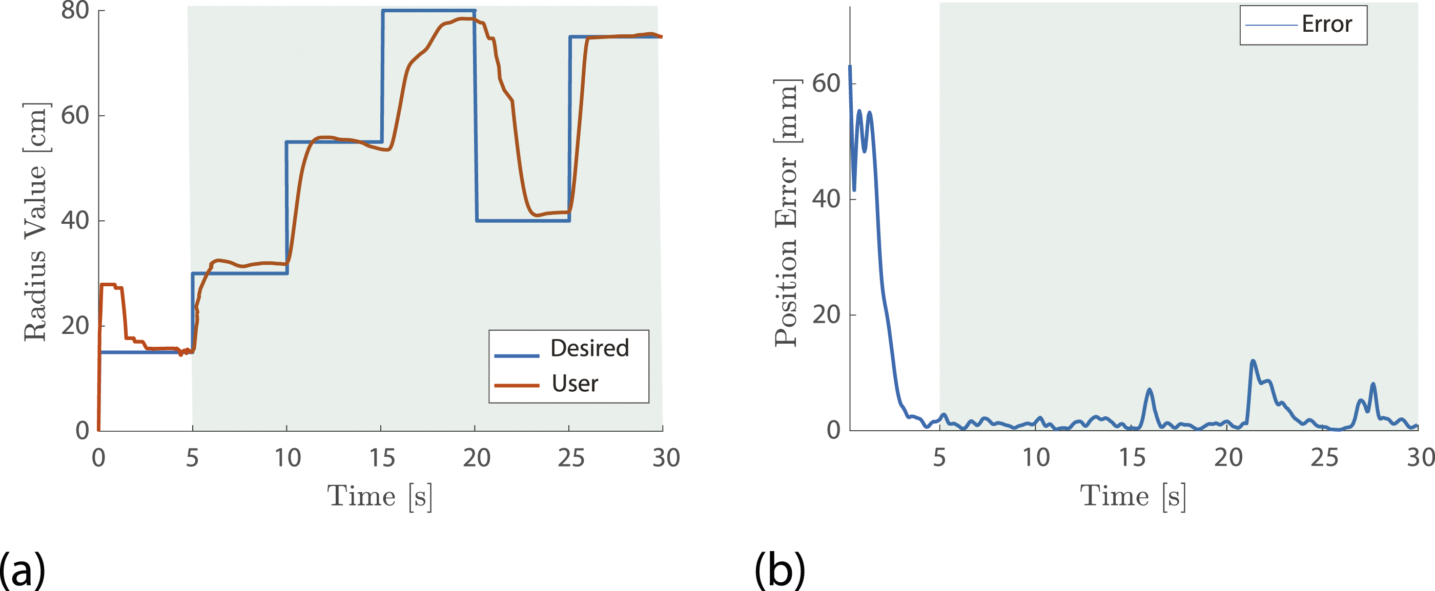
A representative trial of Experiment 1. (a) Desired and actual radius values are reported in blue and red, respectively. (b) The error in accomplishing the primary task position matching. The green background highlights data considered for the analysis.
7. Experiment 2 – control ability and practice
7.1. Experiment description
In the second experiment, we aimed at assessing and evaluating users’ control ability by quantifying whether and how fast a control based on the Intrinsic Kinematic Null Space improves with practice. Hence, here we answer the question “How is the user control ability affected by practice considering the difficulty of the task?” A virtual environment was developed in Unity using C# for the purpose, and rendered using a Samsung HMD Odyssey.
The experiment was designed as a sequence of 14 blocks. In all blocks, the user was asked to use their hand position (tracked using the retroreflective marker attached on the hand back, see Figure 5(a)) to directly control the position of a cursor and match a target placed in one of the nine spatial positions around the rest position, which was a sphere located in front of the right shoulder with the elbow at 90° flexion. However, while in the first and the last blocks (B1 and B14) both cursor and target were spherical in shape (see Figure 8(a)), in the remaining blocks (B2 to B13) they were prolate spheroids (see Figure 8(b)). In fact, in these blocks the user was asked to control simultaneously cursor position and orientation around the axis passing through the equatorial radius of the spheroid and normal to the targets plane, exploiting the IKNS-based control signal to adjust the orientation. The user was tasked to use the hand position to control the position of a cursor (depicted in red) and match a target (depicted in grey) placed in one of the nine positions around the rest position (depicted in blue). In (a), cursor and targets are spherical in shape as proposed in blocks B1 and B14. In (b), cursor and targets are prolate spheroids as displayed in blocks B2 to B13. Here, the user was asked to control the cursor orientation exploiting the IKNS-based control signal. Blocks order is reported in Figure 4.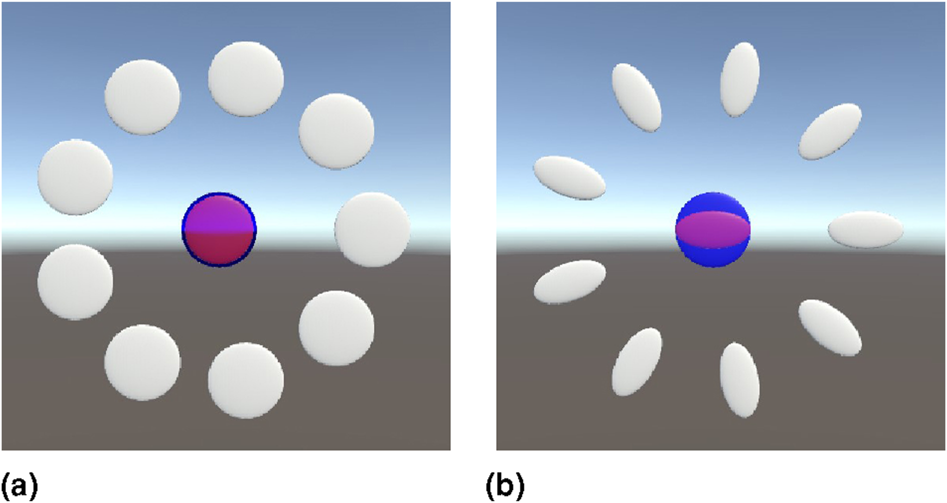
Each block was made of three cycles, in each of which the user was asked to match nine targets, that is, one per spatial position, for a total of 27 targets per block. The sequence of spatial positions was pseudo-randomly ordered for each cycle. Each target remained active for 10 s, and participants were instructed to match the target (only reaching in B1 and B14, reaching and orienting in B2–13) as fast as possible, and then hold the cursor on the latter for the remaining time, until the target disappeared. To standardize target distances, at the beginning of each block and after the expiration of each target, the user was asked to reach the rest position to activate the next target. The rest position was always spherical regardless of the block, hence it was considered matched when the cursor lied within the spatial threshold for 1 s, without considering the cursor orientation. As regards targets, depending on the current block they were considered matched when position (in B1 and B14) or both position and orientation (in B2–13) of the cursor were within angular and spatial tolerances. The distance between cursor and goal was computed as the Euclidean distance between the respective centres. Rest position and targets were coloured blue and grey, respectively, and they turned into green when the cursor was within thresholds, to inform the user about the occurred match. Only one goal at a time was shown in the virtual environment.
Before the start of each block, a quick procedure allowed the experimenter to set the virtual environment parameters with respect to the user’s workspace. In particular, the user was asked to move the hand to firstly indicate the rest position, saved as 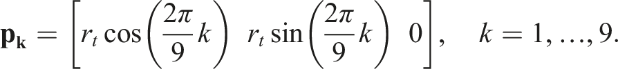
As regards blocks B2–13, targets were oriented with the major axis passing through the circumference radius r
t
, that is,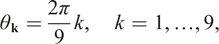
After the calibration procedure, participants sat on a chair, wore the HMD displaying the virtual environment of the experiment, and placed their right wrist on an arm support with gravity compensation (SaeboMAS, Saebo, USA) to reduce muscle fatigue during the experiment. Before the experiment started, each participant had 3 min to familiarize with the control by freely moving and orienting the cursor, and a resting period of 15 min was given at the end of each block. Data were logged with a rate of 100 Hz so that the entire experiment could be played back for the purposes of the analysis.
7.2. Metrics of interest
Only data acquired during the phases in which users were asked to move the cursor from the rest position to the target were considered for the analysis.
Task performance was evaluated considering four metrics: (i) reaching success rate, computed as the percentage of reached targets in the block, (ii) holding success rate, computed as the percentage of targets held for at least 1 s in the block, (iii) holding time, computed as the maximum time the cursor held the target matched within 10 s, and (iv) angular error, computed as the difference between cursor and target orientation when the cursor position was within the spatial tolerance. It is worth noting that during the experiment participants were instructed to hold the target as long as possible, and the time limit of 1 s was set a posteriori following the methodology presented in Gurgone et al. (2022). This decision was driven by two key factors. Firstly, by instructing the subjects to hold the position for as long as possible, we aimed to avoid introducing additional complexity associated with the need for mental estimation of the holding duration. Secondly, this approach allowed for further data analysis (refer to Section Experiment 2 – Results and Discussion – Movement models).
Furthermore, two additional metrics were investigated: angular and spatial velocities of the cursor. The two velocities and the related peaks were analyzed to assess whether different participants used different strategies for reaching and matching the targets.
Finally, we adopted an information theory-based approach based on Fitts’ Law (Fitts, 1954) to devise a model of the participant motor behaviour. It predicts movement time MT to a target as a linear function of an index of difficulty ID of the target, that is,
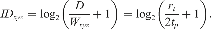
Following the formulation presented by MacKenzie (1992), a target having width W at distance D has an ID equal to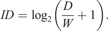
In this work, the ID definition was adapted to account for the real complexity of the task proposed within the experiment. As first step, we consider the distinction between spatial ID (ID
S
) and temporal ID (ID
T
), which is needed to account for both reaching and holding difficulties. This leads to the interpolation of two different movement times, that is,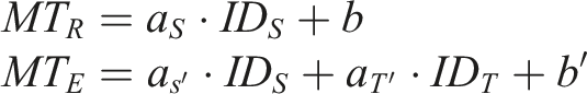

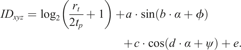
The coefficients of the linear combination (i.e., a, b, c, d, e, ϕ, and ψ) were calculated by fitting movement times to ID
xyz
in B1 and B14 (R2 = 0.74). The rotation ID was defined as follows: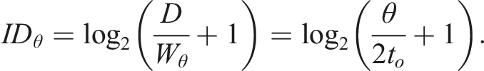
As regards the temporal ID, an approach similar to the one adopted for the ID general definition leads to the following expression: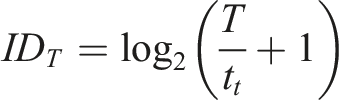

As last measure of performance obtained from the Fitts’ Law, we considered the throughput, which is defined as the ratio between the index of difficulty and the movement time. Since the information rate of the holding task was fixed, we considered only the throughput associated with the reaching task, that is, the ratio between ID S and MT R .
7.3. Results and discussion
Data collected during the experiment were statistically analyzed using MATLAB and SPSS (SPSS 20, IBM).
7.3.1. Task performance
Performance in B1 was evaluated to establish a baseline for the users’ control ability. Results for each participant are detailed in Table 4. On average, participants reached the target 98 ± 4% of the times, and held it for at least 1 s 77 ± 19% of the times. Mean holding time across participants was 2.86 ± 1.06 s out of the 10 s target duration. These results suggest that, when controlling only the position of the cursor, participants easily reached the target, but held it with more difficulty. Moreover, the large standard deviations observed in the holding success rate and in the holding time are indicative of a considerable variability in the holding task performance between users.
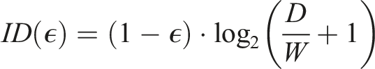
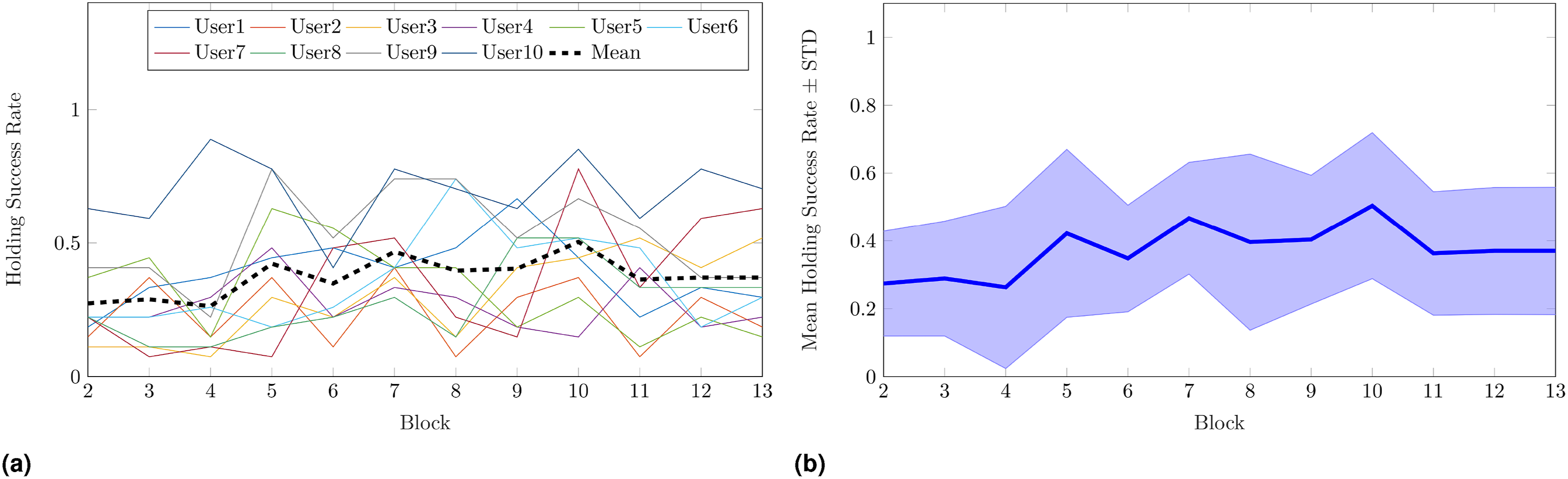
As regards blocks B2–13, on average both success rates increased with block progression. Mean reaching success rate went from 50 ± 35% in B2 to 66 ± 32% in B13, while mean holding success rate started from 27 ± 31% in B2, and reached 37 ± 33% in B13. Reaching and holding success rates across blocks for each participant are reported in Figures 9(a) and 10(a), respectively, whereas in Figures 9(b) and 10(b) we depict the corresponding mean values and standard deviations. A generalized linear mixed model (GLMM) analysis with target and cycle as fixed effects and participant as random effect was performed on both success rates to assess whether the latter significantly increased with practice. Results showed a statistically significant dependence of reaching success rate on cycle (p < .001) and target (p < .001), with a slope of 0.026 per cycle. Similarly, holding success rate significantly increased depending on cycle (p < .001) and target (p < .001), with a slope of 0.016 per cycle. These outcomes indicate not only that practice positively influences users’ control ability, but also that the target-specific difficulty needs to be taken into account. In fact, it is reasonable to expect that different target positions and orientations make the latter more or less difficult to match. Additionally, the fact that the holding success rate had a lower increase rate with respect to the reaching success rate is in line with our expectations, as holding the target revealed to be challenging even in B1, when the user was asked to control the cursor position only. Reaching success rate in Experiment 2. Mean rates in each block (B2–13) for all participants are reported in (a), whereas mean value and standard deviation across participants are in (b). Mean reaching success rate went from 50 ± 35% in B2 to 66 ± 32% in B13. A GLMM analysis with target and cycle as fixed effects, and participant as random effect, showed a statistically significant dependence of reaching success rate on cycle (p < .001) and target (p < .001), with a slope of 0.026 per cycle. Holding success rate in Experiment 2. Mean rates in each block (B2–13) for all participants are reported in (a), whereas mean value and standard deviation across participants are in (b). Mean holding success rate started from 27 ± 31% in B2 and reached 37 ± 33% in B13. A GLMM analysis with target and cycle as fixed effects, and participant as random effect, assessed that the holding success rate significantly increased depending on cycle (p < .001) and target (p < .001), with a slope of 0.016 per cycle.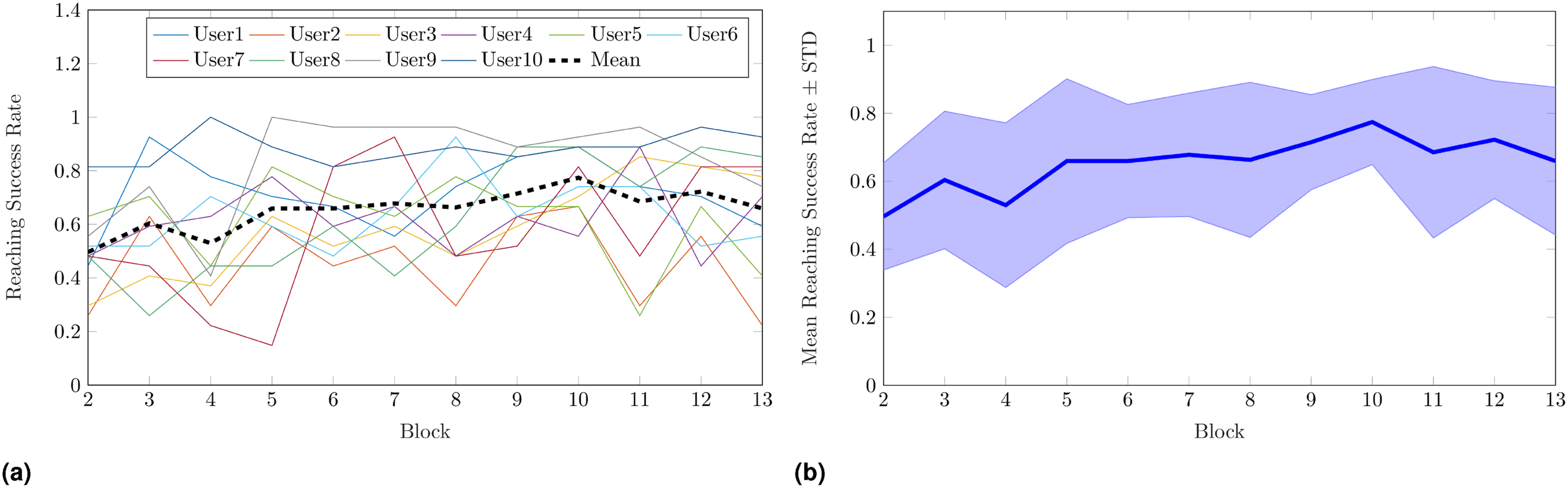
p-values for the effect of cycle on success rate (reaching and holding), holding time, and angular error in Experiment 2.
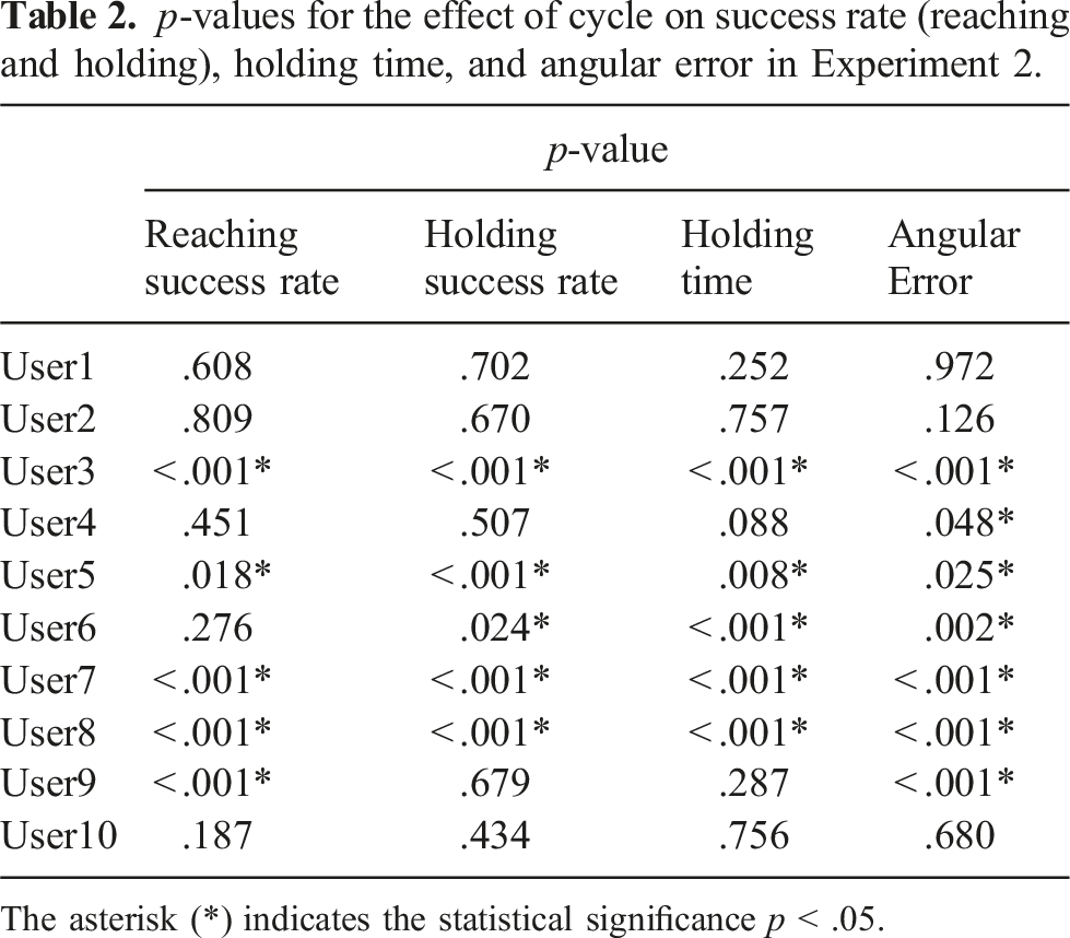
The asterisk (*) indicates the statistical significance p < .05.
p-values for the effect of target on success rate (reaching and holding), holding time, and angular error in Experiment 2.
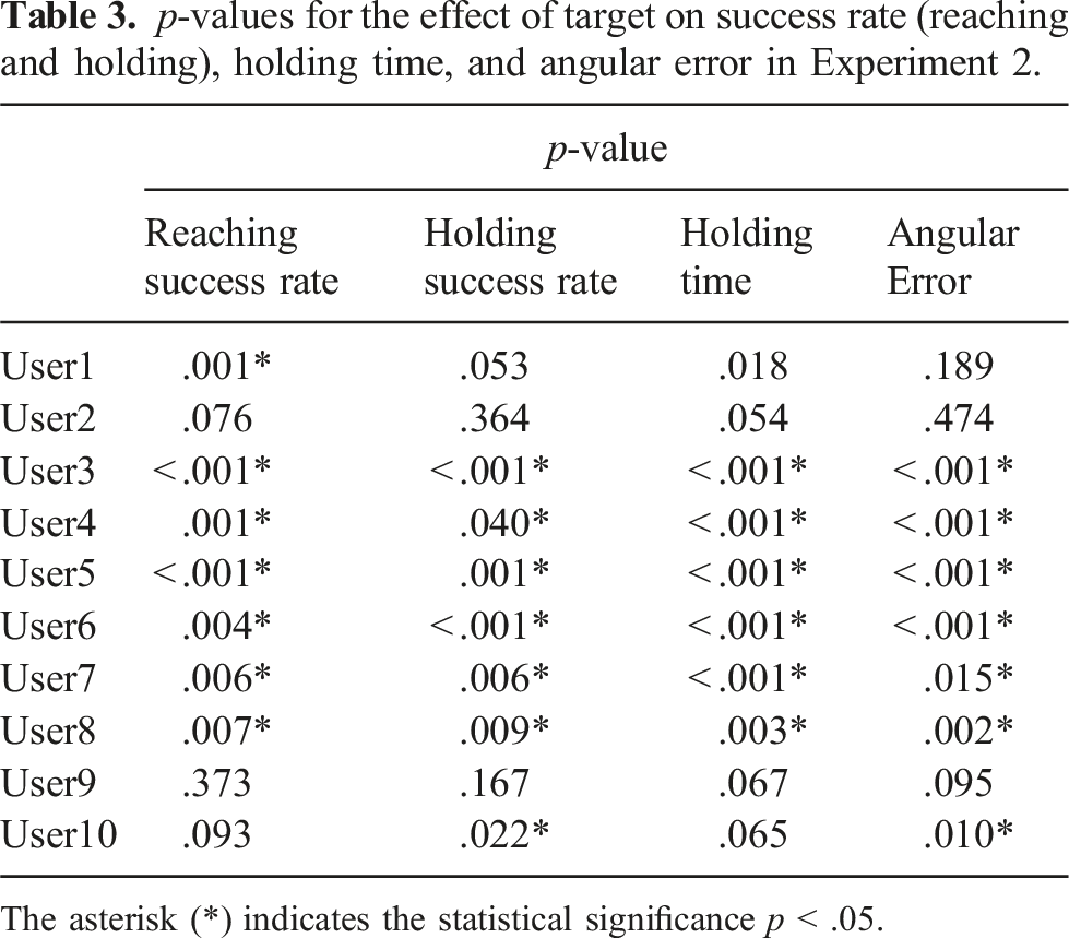
The asterisk (*) indicates the statistical significance p < .05.
Holding time across blocks for each participant is reported in Figure 11(a), while the corresponding mean value and standard deviation are depicted in Figure 11(b). In this case, mean holding time raised from 0.71 ± 0.50 s in B2 to 0.99 ± 0.44 s in B13. A linear mixed model (LMM) analysis with target and cycle as fixed effects, and participant as random effect was performed on the holding time to assess whether the improvement was significant. Both cycle (p < .001) and target (p < .001) had statistically significant effects on holding time, with a slope of 0.011 s per cycle. As expected from performance in B1 and results on the holding success rate, on average it was difficult to maintain the cursor on the target, and the improvement with blocks was small compared to the one observed for the previous metrics. By practicing the IKNS-based control during the experiment, users learned to reach and hold the target for a small amount of time, and these results suggest that it needs more practice to further improve the holding time. Indeed, although the holding time increase was found to be significant, on average at the end of the experiment participants were still unable to hold the target matched for 1 s, that is, the minimum time required for accomplishing the holding task. Holding time in Experiment 2. Mean rates in each block (B2–13) for each participant is reported in (a), whereas mean value and standard deviation across participants are in (b). Mean holding time raised from 0.71 ± 0.50 s in B2 to 0.99 ± 0.44 s in B13. A LMM analysis with target and cycle as fixed effects, and participant as random effect, revealed that both cycle (p < .001) and target (p < .001) had statistically significant effects on holding time, with a slope of 0.011 s per cycle.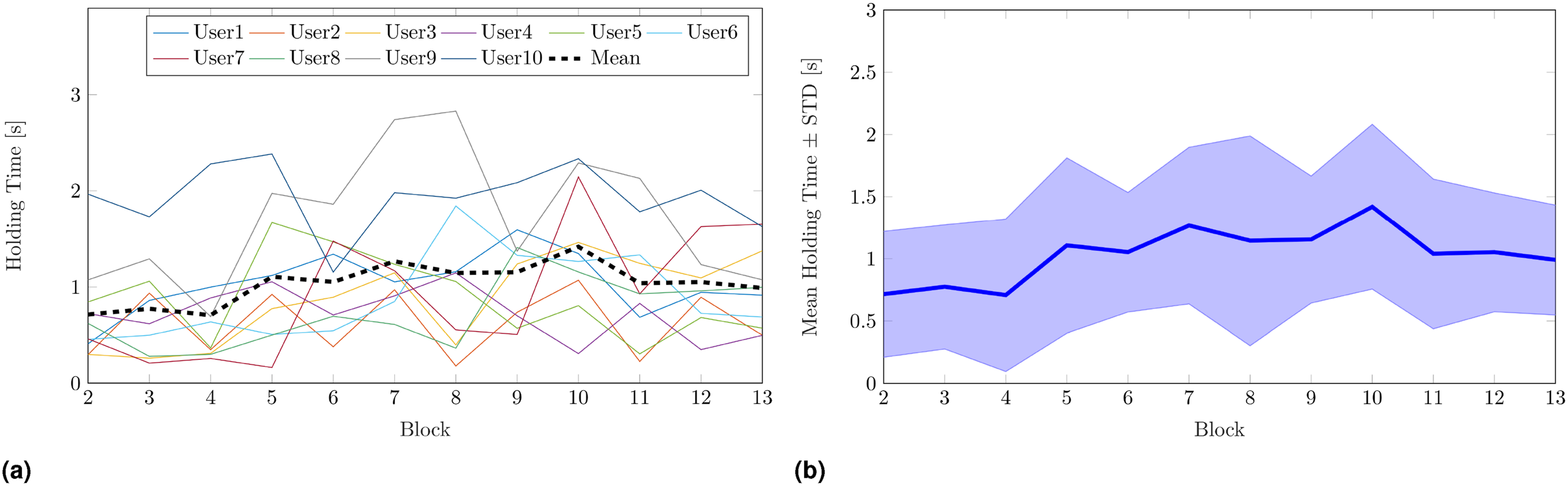
Subject-specific linear models (LMs) with cycle and target as fixed effects were fitted for each participant. P-values for the effects of cycle and target on holding time for each participant are reported in Tables 2 and 3, respectively. A significant effect of cycle on holding time was found for five participants over 10, while the target effect was significant for seven participants.
Mean angular error went from 10.28 ± 3.63 deg in B2 to 7.47 ± 3.43 deg in B13. Angular error on varying block for each participant is reported in Figure 12(a), while the corresponding mean value and standard deviation are depicted in Figure 12(b). The LMM analysis with target and cycle as fixed effects, and participant as random effect revealed a statistically significant dependence of angular error on cycle (p < .001) and target (p < .001), with a slope of −0.14 deg per cycle. Considering that the angular error was computed when the cursor position was within the spatial tolerance, the significant decrease observed demonstrates that, with respect to B2, at the end of B13 users were able to place the cursor on the target with an orientation closer to the one requested. In other words, this indicates that users familiarized themselves with the control, and were able to move and orient the cursor in a more combined rather than sequential manner thanks to practice. Angular error on varying block (B2–13) for each participant is reported in (a), whereas mean value and standard deviation across participants are in (b). Mean angular error went from 10.28 ± 3.63 deg in B2 to 7.47 ± 3.43 deg in B13. A LMM analysis with target and cycle as fixed effects, and a participant as random effect, showed a statistically significant dependence of angular error on cycle (p < .001) and target (p < .001), with a slope of −0.14 deg per cycle.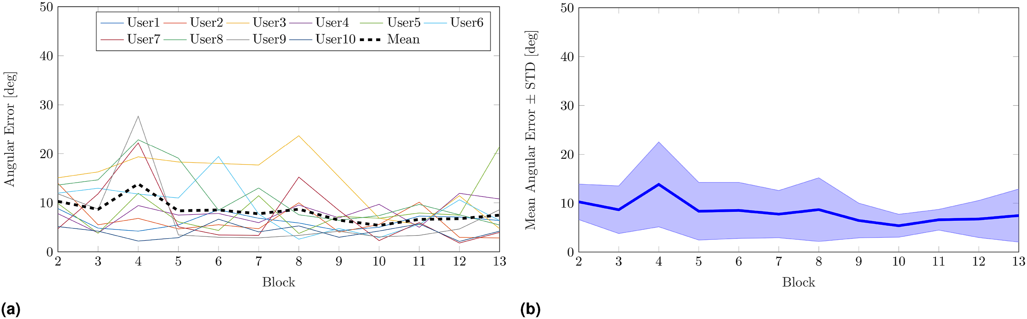
A subject-specific LM analysis with cycle and target as fixed effects was repeated for each participant, and both cycle and target had significant effects on angular error for seven participants over 10. P-values for the effects of cycle and target on angular error for each participant are reported in Tables 2 and 3, respectively.
A speculative discussion of the p-values obtained for the subject-specific GLM analyses led to the following observations. The fact that the cycle effect was significant on task performance for half of the participants may suggest that 12 blocks were not always enough to have an impact on performance. This holds for instance for User2, which started the experiment with the lowest reaching success rate among all the users (26 ± 13% in B2) and did not learn an efficacious strategy for reaching the target before the experiment ended (22 ± 22% in B13, i.e., again the worst reaching success rate among the users). Anyway, the case of User2 is not the only possible explanation. Participants that obtained high performance since B1 were mostly able to maintain such performance throughout the experiment, thus no significant improvements were detected in their control ability. For example, User10 outperformed the other subjects in all the considered metrics, going from 81 ± 17% in B2 to 93 ± 6% in B13 of reaching success rate, from 63 ± 6% in B2 to 70 ± 6% in B13 of holding success rate, from 1.97 ± 0.27 s in B2 to 1.63 ± 0.12 s in B13 of holding time, and from 5.28 ± 4.23 deg in B2 to 4.72 ± 1.24 deg in B13 of angular error. Similarly, User9 went from 41 ± 23% in B2 to 37 ± 6% in B13 of holding success rate, and from 1.07 ± 0.55 s in B2 to 1.08 ± 0.22 s in B13 of holding time. In other words, since B2 performance of User9 was higher than the mean holding success rate (37 ± 33%) and the mean holding time (0.99 ± 0.44 s) across participants in B13.
Target effect on task performance was statistically significant for most of the users (see Table 3). This result is consistent with the intrinsic difficulty in matching targets placed close to the boundaries of the arm workspace. Indeed, even if the IKNS-based control signal range is constant in the workspace, the range of motion of the arm changes with respect to the arm posture. This causes changes in the control signal resolution too; therefore, precisely controlling the orientation of the cursor at points where the arm has reduced mobility is more difficult than at points where the range of motion is large. This is further confirmed by the mean target reaching success rates across participants and blocks. On average, Target1, Target2, and Target3, which were the targets with the highest reaching success rates, were reached 74 ± 18%, 73 ± 12%, and 74 ± 18% of the times, respectively. These targets were placed in the upper right region of the workspace, thus in the region where the kinematic reachability of the human arm workspace is maximized (Zacharias et al., 2010). Hence it is plausible to assume that the human arm’s capabilities are best in this region. On the contrary, the targets with the lowest reaching success rates were Target4 (55 ± 21%), Target7 (56 ± 26%), and Target9 (57 ± 19%), the matching of which required a greater arm extension that in turn corresponded to a smaller range of motion.
Task performance observed in the first (B1) and the last (B14) blocks of Experiment 2.
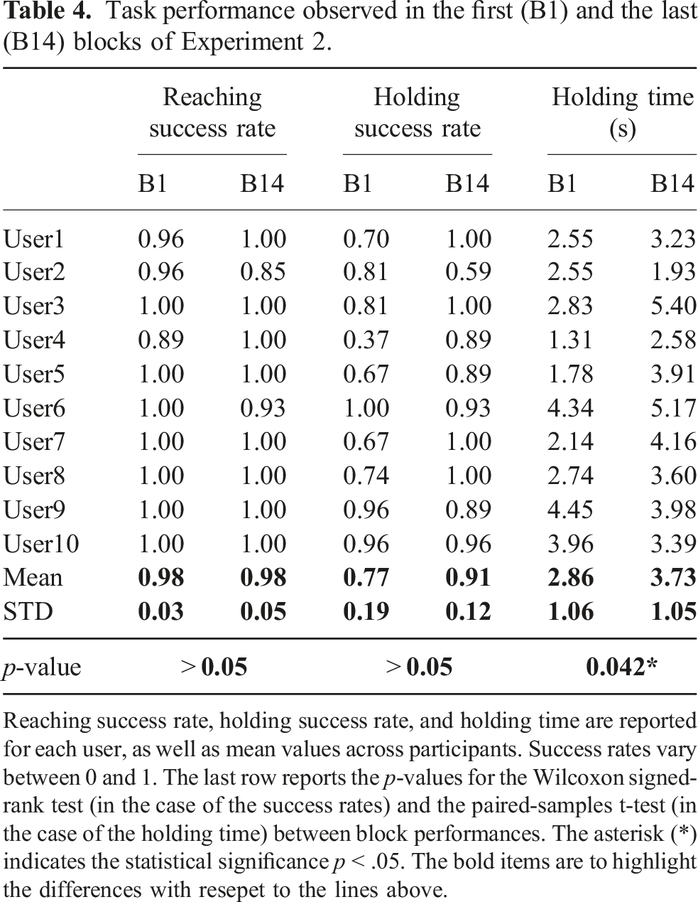
Reaching success rate, holding success rate, and holding time are reported for each user, as well as mean values across participants. Success rates vary between 0 and 1. The last row reports the p-values for the Wilcoxon signed-rank test (in the case of the success rates) and the paired-samples t-test (in the case of the holding time) between block performances. The asterisk (*) indicates the statistical significance p < .05. The bold items are to highlight the differences with resepet to the lines above.
A statistical analysis was conducted to assess whether there was a statistically significant difference in performance between the first and the last block. A Wilcoxon signed-rank test was used to understand whether there was a significant difference between the average success rates. No significant differences were found between B1 and B14 as regards reaching (p > .05) and holding (p > .05) success rates. Holding times were compared using a paired-samples t test. Differences between the holding times observed in B1 and in B14 were normally distributed, as assessed by Shapiro–Wilk’s test (p = .328). On average, participants held the cursor on the target for a longer time in B14 (3.73 ± 1.05 s) as opposed to B1 (2.86 ± 1.06 s), and the increment of 0.86 s was found to be statistically significant (t (9) = 2.36, p = .042). These results are consistent with our previous findings. The experience made users gain confidence in the system, and the statistically significant increment of the holding time is proof of the acquired ability to control cursor position. The fact that no statistically significant differences were found in the success rates is reasonable as, on average, in B1 users were already able to maintain the cursor located on the target for more than 1 s. As a final remark, it is interesting to notice that practicing with the IKNS (repeating blocks B2–B14) does not affect the users’ natural control strategy.
7.3.2. Movement strategies
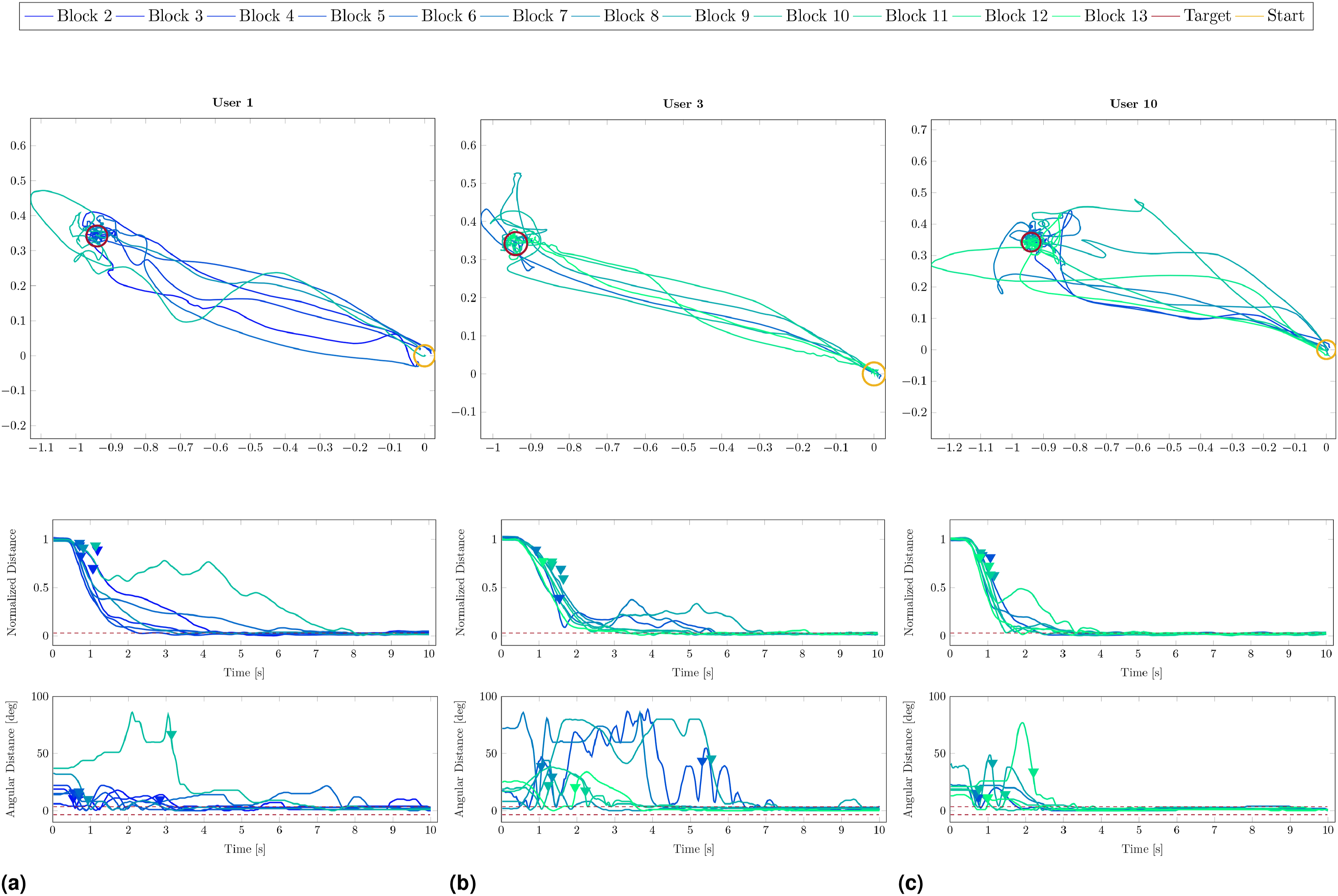
Outcomes of the previous analyses demonstrated large inter-individual variability in task performance, hence we decided to further investigate whether users adopted different movement strategies to accomplish the task. In particular, we were interested in understanding if users tended to firstly align the cursor with the target orientation and then move the cursor in the target position or, conversely, if they firstly minimized the distance and then adjusted the orientation. Examples of strategies adopted by the same user for different targets and by different users for the same target are reported in Figures 13 and 14, respectively. In this light, for each target presented in B2–B13, we considered users’ specific timing of peak linear velocity and peak angular velocity of the cursor. Movement strategies adopted by a representative participant (User9) to accomplish the task for Target2, Target6, and Target9 are reported in (a), (b), and (c), respectively. For each block, we depict only data related to the first cycle in which both reaching and holding task were accomplished. Line colour changes with block progression, from dark blue to cyan. For each target, the first graph (from top to bottom) reports the cursor trajectory projected on the targets plane, the second graph shows the cursor-target distance normalized between 0 and 1, while the last graph depicts the cursor-target angular error. Rest position and target position are highlighted with a yellow circle and a red circle, respectively, whereas triangular marks indicate the first peak linear velocity and peak angular velocity of the cursor for each block. The dashed lines represent the spatial tolerances. Movement strategies to accomplish the task for Target5 adopted by User1, User3, and User10 are reported in (a), (b), and (c), respectively. For each block, we depict only data related to the first cycle in which both reaching and holding task were accomplished. Line colour changes with block progression, from dark blue to cyan. For each user, the first graph (from top to bottom) reports the cursor trajectory projected on the targets plane, the second graph shows the cursor-target distance normalized between 0 and 1, while the last graph depicts the cursor-target angular error. Rest position and target position are highlighted with a yellow circle and a red circle, respectively, whereas triangular marks indicate the first peak linear velocity and peak angular velocity of the cursor for each block. The dashed lines represent the spatial tolerances.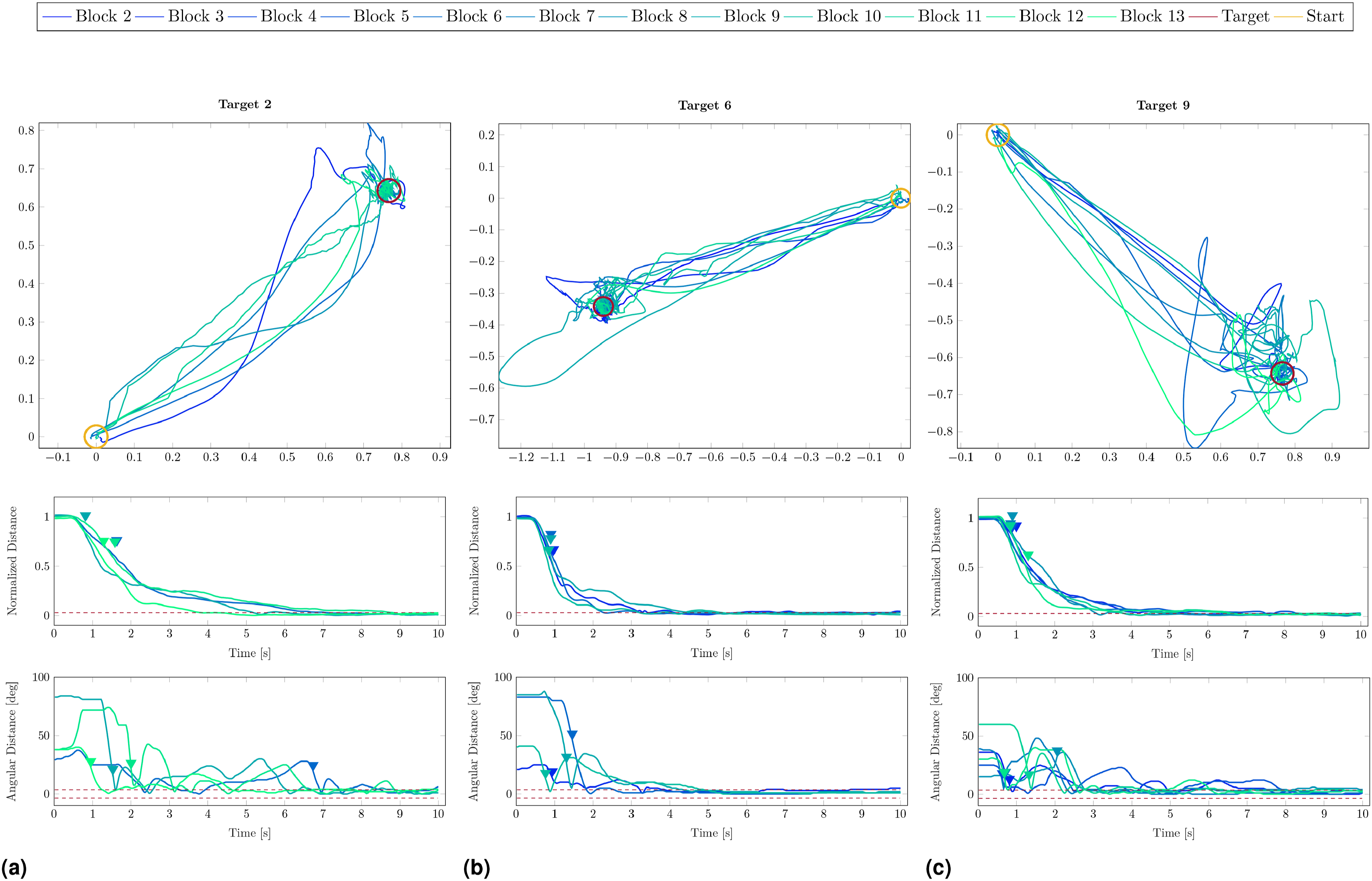
For each user we report the time instant of the linear and angular velocity peaks together with the time interval between the two instants.
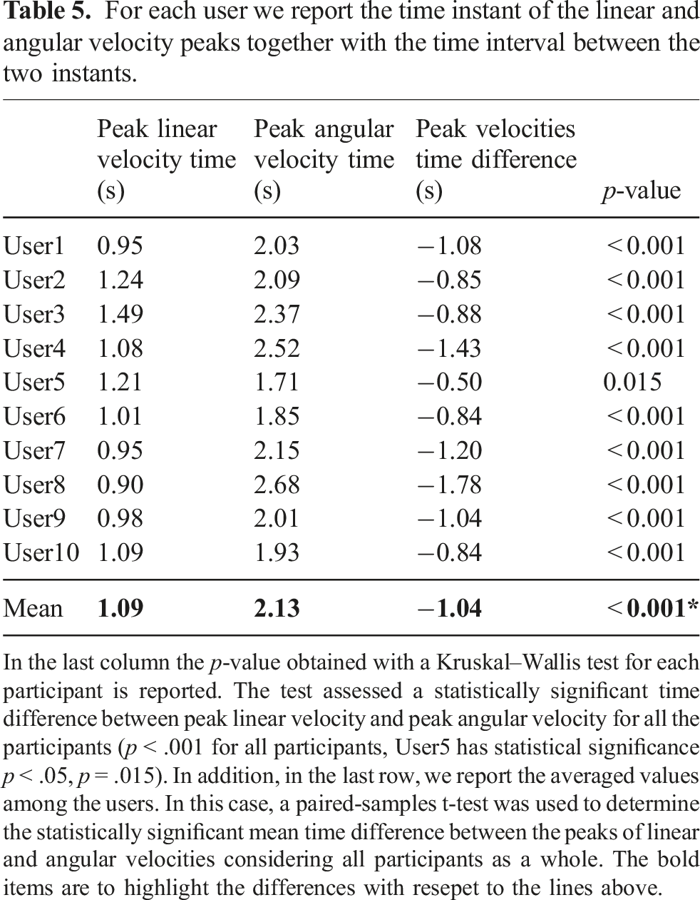
In the last column the p-value obtained with a Kruskal–Wallis test for each participant is reported. The test assessed a statistically significant time difference between peak linear velocity and peak angular velocity for all the participants (p < .001 for all participants, User5 has statistical significance p < .05, p = .015). In addition, in the last row, we report the averaged values among the users. In this case, a paired-samples t-test was used to determine the statistically significant mean time difference between the peaks of linear and angular velocities considering all participants as a whole. The bold items are to highlight the differences with resepet to the lines above.
Finally, we investigated the existence of a correlation between mean peaks time among users and progression in the experiments (cycles and blocks). A Pearson correlation test revealed that neither blocks nor cycles had a statistically significant correlation with both the mean peak linear and mean peak angular velocity times for any of the users. Such results suggest that participants maintained unaltered their strategy throughout the 12 blocks, that is, they adjusted the cursor orientation only when the centre of the spheroids was almost aligned.
7.3.3. Movement models
The throughput on block progression for each participant is reported in Figure 15(a). The mean value across participants went from 0.81 ± 0.07 bit/s in B2 to 0.94 ± 0.11 bit/s in B13. A Pearson correlation test was run to assess the relationship between cycle and mean throughput across participants. Results demonstrated a statistically significant positive correlation between cycles progression and mean throughput increase, r = 0.65, p < .001. Considering that the spatial ID was constant across blocks, a statistically significant increase of the information rate denotes a decrease of the movement time to reach the target. Hence, participants improved their speed-accuracy tradeoff with practice. Individual control abilities. In (a), the throughput (computed as the ratio between ID
S
and MT
R
) as a function of the block progression (B2–13) for each participant. The dashed black line indicates the mean value among users. The corrected spatial ID as a function of the scale factor applied to both spatial tolerances is reported in (b). For each participant, the corrected spatial ID was computed as the mean value across the last three blocks (B11–13). In (c), a representative example (User8, B13) of the total task ID computed as a function of both spatial and temporal tolerances. The maximum total task ID for the reaching and holding task are denoted in the graph with a blue and a red dot, respectively. The simulated temporal evolution of the total task ID computed for each participant considering their optimal thresholds is reported in (d). The dashed black line indicates the mean value among users.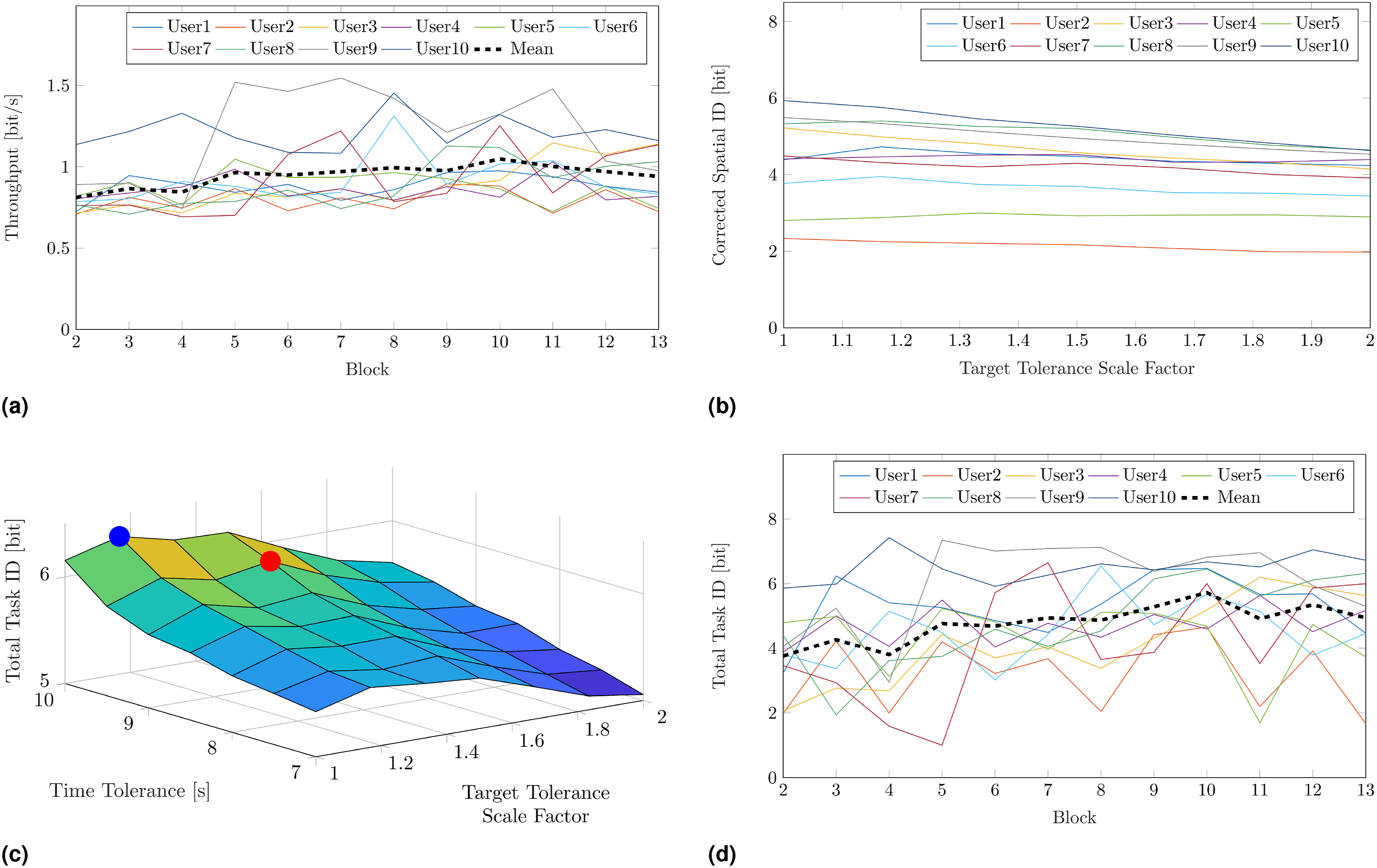
To compute a reliable prediction model of the movement time based on the Fitts’ Law, multiple conditions of accuracy required to complete the task should be considered and tested within the experiment. Anyway, in our case this would have prolonged the experiment too much, with consequent poor reliability of the results because of muscular and cognitive fatigue. Hence, we decided to carry out the experiment with the most strict thresholds (i.e., asking the subjects to perform the tasks with the highest indices of difficulty), and then estimate a posteriori how the performance would have varied if the thresholds had been larger.
Reaching performance was simulated by varying both spatial and angular tolerances, doubling their value in seven steps (i.e., from 3% to 6% of the maximum target distance for t p , and from 4% to 8% of the maximum target orientation for t o ). Similarly, holding performance was simulated by varying the temporal accuracy from t t = 10 s (that is equivalent to just target matching) to t t = 7 s, with a step of 0.5 s. In Figure 15(b), the corrected spatial ID as a function of the scale factor applied to both spatial tolerances is reported. For each participant, the corrected spatial ID was computed as the mean value across the last three blocks (B11–13). Conversely to what could be expected when the thresholds are large, admitting a smaller task accuracy did not reflect in a greater amount of transmitted information for all the participants. Indeed, participants that had a high reaching success rate with the original thresholds maintained their performance when the tasks were simulated with greater thresholds, thus for them the thresholds increment entailed a reduction of the channel capacity. This holds for instance for User3, User8, User9, and User10. On the contrary, the thresholds increment was beneficial for those who did not succeed the reaching tasks during the real experiment (e.g., User4 and User5).
The different trends observed in the corrected spatial ID suggest that there is no optimal a priori target size, but the target size that maximizes the transmitted information varies across participants depending on their control ability. This is further confirmed by the total task ID computed as a function of both spatial and temporal tolerances. A representative example is reported in Figure 15(c), where the maximum corrected spatial ID for the reaching task (i.e., at t t = 10 s) and the maximum total task ID for the reaching and holding task are denoted in the graph with a blue and a red dot, respectively. As it can be noticed, the accuracy leading to the greater total task ID for the reaching and holding task is not at the smallest spatial tolerance. This holds for the other participants too, as on average they had their maximum total task ID when the spatial tolerances were multiplied by 1.23 ± 0.37. On the other hand, all the participants had the higher transmitted information at the smallest time tolerance (i.e., at t t = 9.5 s). This result is reasonable considering the low performance that participants had in the holding task. Indeed, the highest holding success rate always occurs at the lowest temporal ID (that is, if the participant can maintain the target matched for n seconds, then they will be able to maintain it matched for less than n seconds too). In our case, the highest holding success rates were low, hence the increment of the temporal ID did not compensate for the decrease of holding performance, and the corrected temporal ID decreased when the temporal accuracy increased. In Figure 15(d), we report the simulated temporal evolution of the total task ID computed for each participant considering their optimal thresholds. A Pearson test confirmed a statistically significant positive correlation between cycles and total task ID, r = 0.79, p < .001.
Finally, we interpolated the movement times to devise the models of the participants’ motor behaviour. For the reaching task, individual linear fit of MT R versus ID S resulted in an R2 = 0.18 ± 0.17, and the model was significant for seven participants over 10 (p < .05, except for User4, User5, and User8). For the reaching and holding task, individual linear fit of the movement time for the task execution resulted in an R2 = 0.28 ± 0.16, and the fit was significant for 10 participants over 10 (p < .001). In particular, this last result confirmed the validity of the temporal ID, as already observed in Gurgone et al. (2022). In Section Kinematic versus Muscular Null Space, a more detailed discussion and comparison between the two approaches is reported.
8. Experiment 3 – wearable extra-finger
8.1. Experiment description
The third experiment was conducted to assess the effectiveness of our paradigm for commanding a wearable SRL in a real scenario. This experiment addresses the research question “Is the IKNS-based control easy to learn for operating a wearable extra-finger to accomplish common activities of daily living?”
To this aim, leveraging the encouraging preliminary results obtained in the preparatory experiment described in Lisini Baldi et al. (2023), users were asked to perform a repetitive pick-and-place task. They wore a robotic extra-finger on the right forearm, mimicking a post-stroke hemiparesis, and controlled the position of the opening/closing mechanism with the same arm using the control signal based on the IKNS. The wearable robotic finger utilized for the experiments is a modified version of the one presented in Prattichizzo et al. (2014). Specifically, we implemented the mechanical design outlined in Salvietti et al. (2017) and developed a novel firmware version to enable the device control via an external input signal. Indeed, the original version of the finger was controlled using two buttons for opening and closing, while in the modified version the closure is remotely controlled using a serial connection (RS232 protocol, baudrate 115200 bps) with an external PC. The extra-finger was activated in continuous manner, where the maximum value of the IKNS-based control signal (i.e., 1) corresponded to a fully closure of the finger, and the minimum value (i.e., 0) to the maximum opening.
Participants were asked to pick and place a Rubik’s Cube (from the YCB benchmark set (Calli et al., 2015), 64 g, 60 × 60 × 60 mm) in four predefined points of the reachable arm workspace. These points were the corners of a rectangular area, as depicted in Figure 16. Participants were instructed to pick the cube and place it from one point to the next following the rectangle perimeter (clockwise) as many times as possible in a time limit of 3 min. The starting point was on the right lower angle of the arm workspace, and each target position was considered successfully reached (thus, it was counted in the final value) if the cube was correctly placed on it and the subject had opened the extra-finger and raised the hand by around 10 cm. Users repeated the experiment seven times, with a pause of 15 min between each iteration. Experiment 3 setup. Participants were asked to pick Rubik’s Cube and place it from one point to the next one (clockwise) as many times as possible in a time limit of 3 min.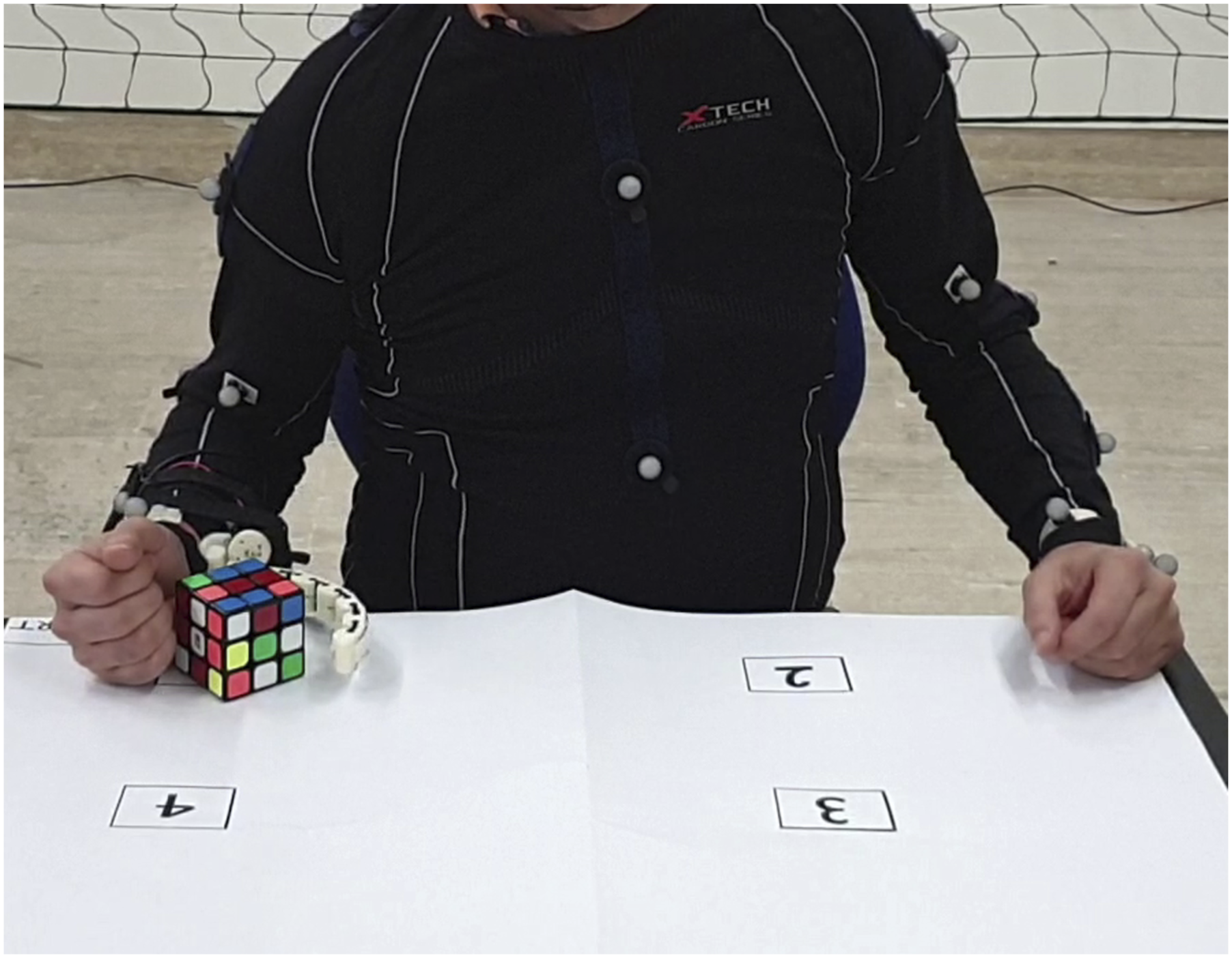
8.2. Metrics of interest
The number of successfully reached target positions was considered as a performance metric and was used to estimate the learning curve describing the average improvement in performance. Since we designed the experiment as a success-based task, we exploited a sigmoid function for modelling and fitting data (Leibowitz et al., 2010). The latter was defined as
8.3. Results and discussion
Results for all participants are shown in Figure 17(a). The relationship between the mean number of successes among the user (reported as a dashed black line in Figure 17(a)) and the trial progression was modelled with the sigmoid described in (3). Figure 17(b) shows the obtained learning curve (R2 = 0.98). Results of Experiment 3. In (a), the number of successfully reached target positions as a function of the trial progression is reported for each participant. The thicker dashed black line shows the mean among all the subjects. In (b), the mean number of successes among all the subjects is reported in solid blue, while the estimated learning curve is depicted with a dashed blue line.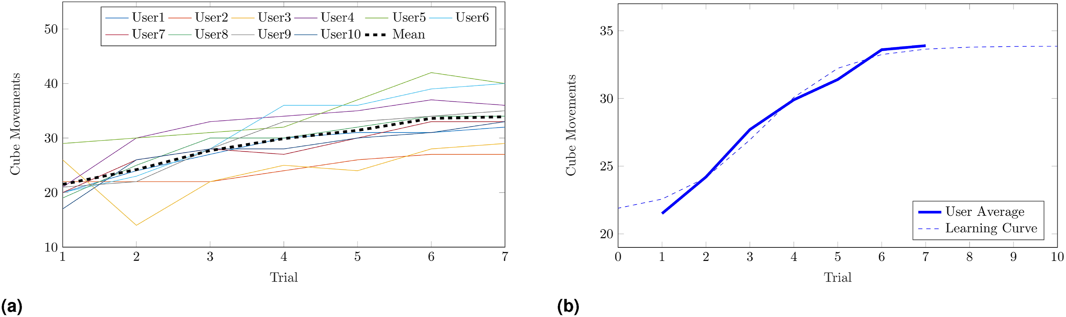
Results show that participants rapidly learned how to use the system, and gained confidence in picking and releasing the cube. The majority of the users (8 over 10) reached a speed of 30 motions in 3 minutes. On average, after seven trials (a total of 21 min of experiments) participants reached the plateau, meaning that asking them to perform further tasks would have led to limited improvement since their learning capacity was reduced.
Even if the aforementioned results may appear coarser compared to the analysis carried out in Experiment 2, here our goal was to provide an initial assessment of the practicality of the approach, showing that it can be used in situations of daily living. The slope of the learning curve demonstrates that with few trials users are able to take advantage of the IKNS-based control for accomplishing dual tasks with a wearable robotic extra-finger. On average, in no more than six trials (18 min of usage) the mean number of cube movements increased by about 80%.
9. Experiment 4 – assistive robotic arm
9.1. Experiment description
The fourth experiment aimed at answering the last research question, that is, “How does user performance in accomplishing common activities of daily living that involve simultaneous tasks differ when using the IKNS-based control compared to an EKNS-based control?”
Participants were instructed to use a grounded supernumerary robotic arm (Kinova Mico2) to pour a glass of water. Similarly to Experiment 3, the participants were given two tasks to complete simultaneously: holding the glass under the bottle, and precisely controlling the robot to pour exactly 30 g of water (refer to Figure 18). A line was marked on the glass to indicate the desired water quantity. Experiment 4 setup. Participants were asked to pour 30 g of water into a glass using a robotic arm. Four different positions in the reachable perispersonal space, detailed in (a), (b), (c) and (d), were proposed. The hand starting position was fixed across the trials.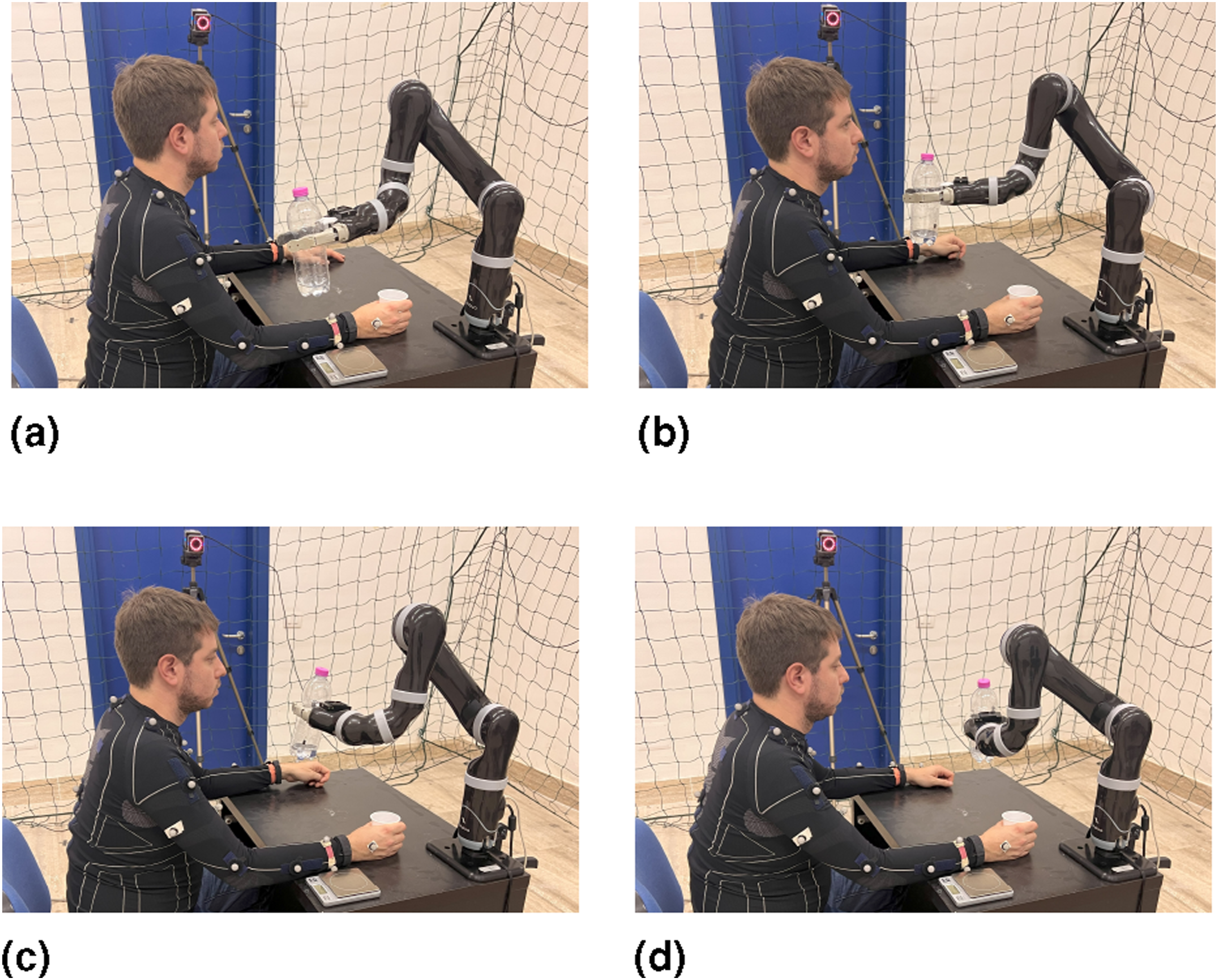
At the onset of the experiment, the SRL had already grasped the bottle. Each participant was then asked to control the velocity of the robotic arm’s last joint to pour the water, which ranged between −30 deg/s and 30 deg/s. In order to enhance the realism of the task, four distinct positions within the reachable peripersonal space were considered. Each participant made three attempts for each end-effector position, resulting in a total of 12 trials per subject, proposed in a pseudo-random order. As visible in Figure 18, the hand starting position was the same for all the trials. After each trial the quantity of poured water was evaluated using a scale.
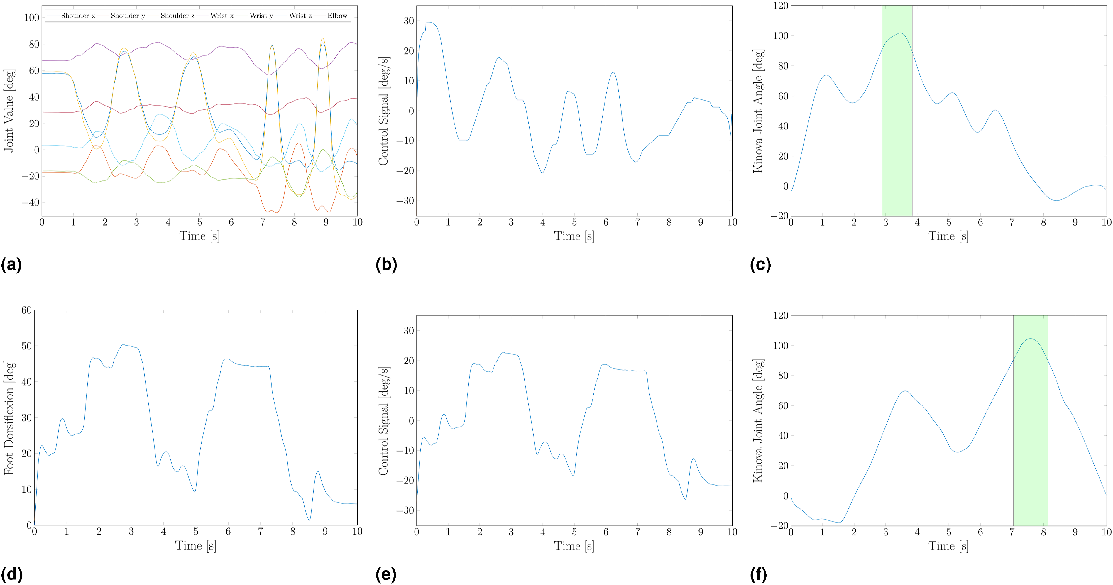
Subjects were asked to repeat the task under two experimental conditions, that is controlling the velocity of the joint using once the IKNS-based control signal extracted from the same arm holding the glass, and once using the EKNS-based control signal extracted from the dorsiflexion of their right foot. The latter was reconstructed online using four retro-reflective markers attached to the subject’s right foot, and the software Vicon Tracker 3.0 (Vicon Motion Systems Ltd, UK). Among the possible joint motions in the Extrinsic Kinematic Null Space, we have opted to derive the control signal from the dorsiflexion of the joint of the ankle due to the familiarity individuals have with this specific movement, often used for driving the car. For enabling the EKNS condition, the calibration phase of this experiment was enlarged with a further step in which subjects were asked to dorsiflex their right foot 10 times. For each motion, the maximum angle between the ground and the sole of the foot was recorded, and the average of these values was used as a normalization factor. Thus, in accordance with (2), the control signal f, associated to the foot motion is calculated as Representative trials of Experiment 4. Upper panel, IKNS-based control signal extracted from the movement of the same arm holding the glass. Arm joint values (a) recorded with Vicon Nexus are used to extract the control signal (b), which is then used to control the velocity of the robotic arm’s last joint. In (c), the resulting joint value. Lower panel, EKNS-based control signal extracted from the dorsiflexion of the right foot. Ankle value (d) recorded with Vicon Tracker is used to compute the control signal (e) as in (3), which is then used to control the velocity of the robotic arm’s last joint. In (f), the resulting joint value. The green background highlights the phases in which the water is poured into the glass.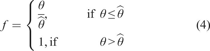
9.2. Metrics of interest
The deviation from the desired water quantity ϵ and the completion time τ were used as evaluation metrics.
There were 60 g of water in the bottle, meaning that the maximum possible absolute error in pouring the water was 30 g. The completion time of the trial was measured from the moment the glass was lifted from the starting position until it was placed back on the desk, returning in the starting position.
9.3. Results and discussion
Error in pouring the water in Experiment 4 using the IKNS approach.
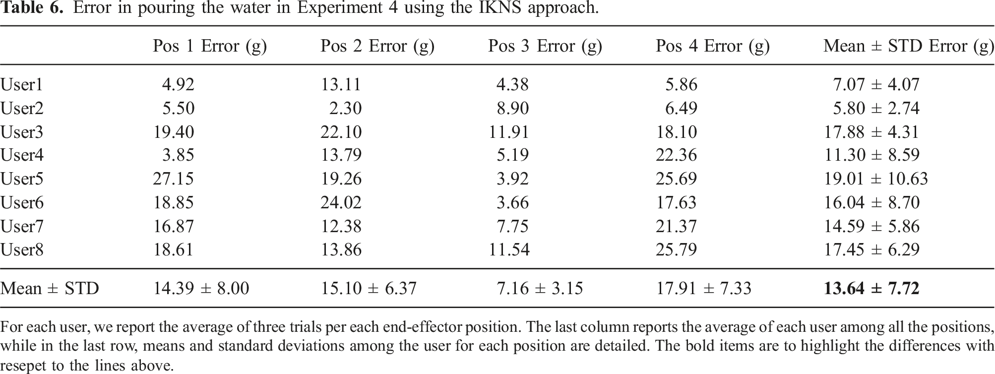
For each user, we report the average of three trials per each end-effector position. The last column reports the average of each user among all the positions, while in the last row, means and standard deviations among the user for each position are detailed. The bold items are to highlight the differences with resepet to the lines above.
Error in pouring the water in Experiment 4 using the EKNS approach.
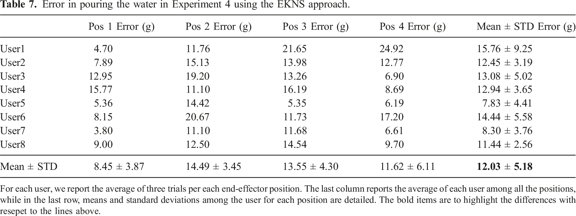
For each user, we report the average of three trials per each end-effector position. The last column reports the average of each user among all the positions, while in the last row, means and standard deviations among the user for each position are detailed. The bold items are to highlight the differences with resepet to the lines above.
Time needed by the user to accomplish the task in Experiment 4 using the IKNS approach.
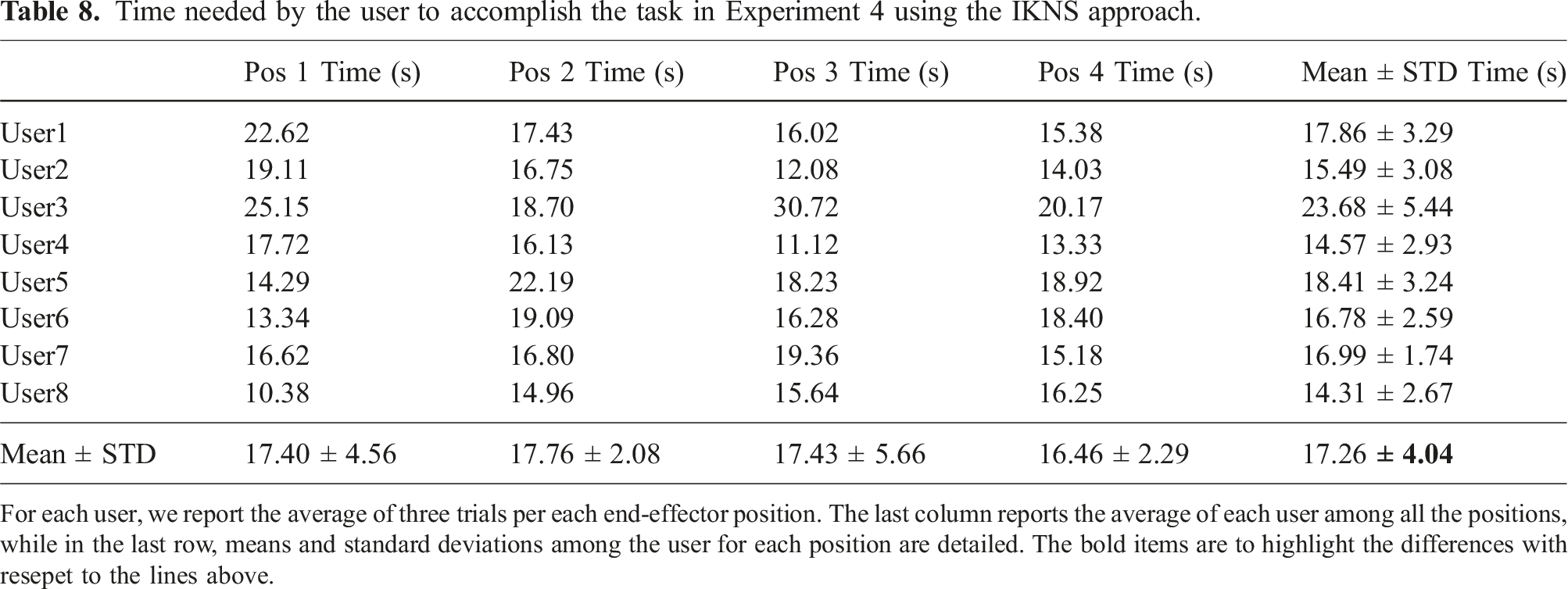
For each user, we report the average of three trials per each end-effector position. The last column reports the average of each user among all the positions, while in the last row, means and standard deviations among the user for each position are detailed. The bold items are to highlight the differences with resepet to the lines above.
Time needed by the user to accomplish the task in Experiment 4 using the EKNS approach.
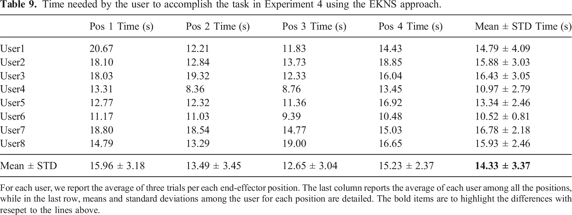
For each user, we report the average of three trials per each end-effector position. The last column reports the average of each user among all the positions, while in the last row, means and standard deviations among the user for each position are detailed. The bold items are to highlight the differences with resepet to the lines above.
The obtained results were in line with our expectations. Statistical analysis demonstrated that the differences in water pouring accuracy between the IKNS and EKNS methods were not statistically significant. However, it is worth noting that using the IKNS to control the SRL required more time to complete the pouring task. Taking into consideration the results obtained in Experiment 2 and Experiment 3, this discrepancy in pouring time can be consistently attributed to the participants’ unfamiliarity with the IKNS method. In contrast, they were well accustomed to the EKNS method, which mimics the motion of a car’s accelerator pedal. This familiarity with the EKNS method likely allowed participants to perform the pouring task more efficiently, leading to shorter completion times compared to the relatively unfamiliar IKNS method.
10. Kinematic versus muscular null space
In terms of task performance and motor skill learning, we can compare results of Experiment 2 with those obtained using the intrinsic muscular null space (Gurgone et al., 2022). Despite a few differences in the experimental protocol (e.g., target arranged in a vertical plane in the current study and in a horizontal plane in Gurgone et al. (2022)), in both cases participants were asked to simultaneously adjust the displacement and the orientation of an elliptical cursor to match the position and orientation of several elliptical targets.
Reaching success rate in the first null space control block was 50 ± 35% (mean ± standard deviation across participants, N = 10) for IKNS and 72 ± 26% for IMNS (N = 8). Performance increased in both cases, with a reaching success rate of 66 ± 33% for IKNS and 93 ± 11% for IMNS. Similarly, holding success rate in the final block was 37 ± 33% for IKNS and 43 ± 31% for IMNS. Even though performances were comparable, IMNS outperformed IKNS in all the cases in terms of absolute values. A possible explanation for this difference is that the spatial IDs in the case of IKNS were higher than the ones proposed in the case of IMNS. Another hypothesis supported by a kinematic analysis of the human arm suggests that as the arm approaches the singularity configuration, the range of motion within the IKNS diminishes, making it more challenging to control the orientation of the cursor.
When comparing the two approaches, it is crucial to take into account both their potential for exploitation and any practical limitations they may have in real-life applications. On the one hand, when utilizing the kinematic null space, users have to pay attention to their surrounding, avoiding potential obstacles. On the other hand, using the muscular kernel limits the stiffness control of the involved link. For example, if the user seeks to control an additional degree of freedom by co-contracting forearm muscles, this might interfere with a precise adjustment of arm impedance. Considering the number of available null space dimensions in the upper limb, it is important to note that despite the arm having seven kinematic degrees of freedom controlled by 18 muscles (Halim, 2008), not all of these dimensions are effectively exploitable for muscular control.
The advantages and disadvantages preliminarily discussed in this section are instrumental for a more comprehensive and detailed comparison, which will be the focus of future work.
11. Limitations
In this section we summarize the main limitations of the IKNS-based approach as identified by the authors during the experiments. Additionally, we will propose potential mitigations to address these limitations.
The first limitation is related to the need of a MOCAP system. Indeed, all the experiments were performed in a room equipped with a Vicon system, and retro-reflective markers were attached to the subject to record arm joint angle values. Despite the limited suitability of a marker-based system for real-world applications, we decided to utilize it due to the paramount importance of high precision and reliability during this validation phase. Once the system attains validation, body tracking can seamlessly transition to more versatile (and potentially wearable) systems which rely on inertial measurements (Lisini Baldi et al., 2019; Mihcin, 2022; Mihcin et al., 2021) or on cameras (Baak et al., 2013; Colombel et al., 2021; Yang et al., 2022).
Another potential limitation of the system could be the suboptimal selection of movements made by users during the initial phase. Users may initially prefer certain motions that could later prove to be unsuitable due to fatigue or other factors. As a result, users would need to reinitialize the system, resulting in a loss of time and inconvenience. To address this, an algorithm can be developed to automatically learn and identify all the motions within the Intrinsic Kinematic Null Space considering also individual users’ preferences and fatigue levels. By continuously analyzing user movements and collecting data, the algorithm could adapt and refine the motion selection process, ensuring that the chosen movements are more suitable for the user’s needs and minimizing the need for system reinitialization. Implementing such an algorithm would not only enhance the efficiency of the system but also provide a seamless and personalized experience for the users, reducing the potential frustration associated with initial motion selection.
12. Conclusions and future work
This study presented a novel approach for controlling extra degrees of freedom of supernumerary robotic limbs exploiting the redundancy of the upper limbs of the human body. This kind of control takes advantage of movements in the Intrinsic Kinematic Null Space for enabling the user to easily and comfortably control robotic devices to accomplish dual tasks. A paradigmatic example of the IKNS potential is the performance of augmented manipulation tasks that require the involvement of both natural and artificial limbs. In such case, the human end-effector is represented by the hand, and the motion of the joints of the shoulder, the elbow, and the wrist that does not generate velocities of the hand can be exploited to compute the signal controlling the artificial limb.
The control of a degree of freedom while simultaneously performing a primary task with the natural limbs requires signals that do not interfere with hand motion. As a first step towards the ambitious goal of augmenting human motor capabilities, we tested whether simultaneous control of natural and extra DoFs through the Intrinsic Kinematic Null Space is a viable solution. To this end, we developed a control strategy that exploits motions within the kinematic null space, and we tested its performance both in virtual and real environments.
The experimental campaign was based on four experiments. With the first experiment we proved that it is possible to use the IKNS to control an additional degree of freedom for executing dual tasks. Indeed, asking users to perform a secondary task controlled through the IKNS-based signal did not affect the performance of the primary task. In the second experiment, we evaluated users’ control ability by quantifying whether and how fast a control based on the Intrinsic Kinematic Null Space improves with practice. An information theory-based approach was adopted to model the participant motor behaviour and generalize the assessment of the control ability beyond the performance achieved with the specific parameters of the experiment. The third experiment was conducted to assess the effectiveness and practicality of our control paradigm in controlling a wearable supernumerary robotic finger in a real scenario, showing that it can be used in situations of daily living. Finally, in the fourth experiment, a comparison was made between approaches utilizing Intrinsic and Extrinsic Kinematic Null Spaces for controlling a grounded supernumerary robotic arm. The results of the experiment revealed that there was no statistically significant difference in task accuracy between the two approaches.
Results here presented pave the way towards a new research field, that is, human sensorimotor augmentation. Future research directions include expanding the IKNS-based control strategy to control a larger number of degrees of freedom, as well as developing novel methods to perform the IKNS identification by means of wearable interfaces able to capture body motions. Moreover, a novel experimental campaign will be conducted for comparing IKNS, IMNS, and a hybrid approach mixing the two schemes, possibly involving the control of multiple-DoF SRLs. Such a comparison requires to conduct multiple experiments sharing the same experimental protocol and the same setup setting.
In conclusion, we demonstrated the feasibility of a novel approach to control an extra DoF exploiting the kinematic redundancy of the kinematic chain of the limb directly involved in a task being performed. Such an approach can be applied to control more sophisticated assistive or augmentative robotic devices (as extra limbs/arm wearable or not) in everyday life situations, for both healthy and impaired people. The proposed method may be used, for instance, by impaired patients to compensate for their disability using the same limb (the healthy one) both to accomplish a task and for controlling a robot in a cooperative way. In addition, our user-centred approach mitigates the risk of long-term injury and reduces fatigue thanks to the fact that the user can perform the most comfortable motions within the null space to control the extra-DoF.
In future studies, we will evaluate the physical and cognitive load needed for using such approach that might me too high for a frail person. A complete analysis will evaluate multiple body locations and a different number of degrees of freedom to be commanded, searching for the best compromise between cognitive load, physical effort, and controllable degrees of freedom.
Supplemental Material
Footnotes
Declaration of conflicting interests
The author(s) declared no potential conflicts of interest with respect to the research, authorship, and/or publication of this article.
Funding
The author(s) disclosed receipt of the following financial support for the research, authorship, and/or publication of this article: This work has received funding from the European Union’s Horizon Europe programme by the project HARIA: Human–Robot Sensorimotor Augmentation – Wearable Sensorimotor Interfaces and Supernumerary Robotic Limbs for Humans with Upper-Limb Disabilities, under grant agreement No. 101070292.
Supplemental Material
Supplemental material for this article is available online.
Note
References
Supplementary Material
Please find the following supplemental material available below.
For Open Access articles published under a Creative Commons License, all supplemental material carries the same license as the article it is associated with.
For non-Open Access articles published, all supplemental material carries a non-exclusive license, and permission requests for re-use of supplemental material or any part of supplemental material shall be sent directly to the copyright owner as specified in the copyright notice associated with the article.