
Abstract
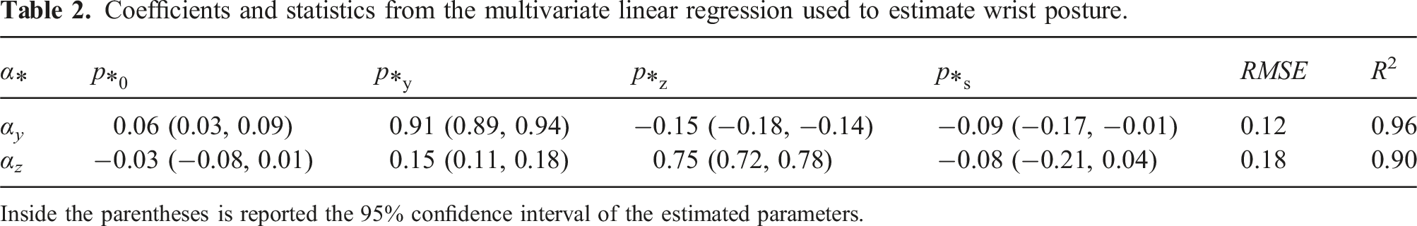
This study introduces an innovative design for a Variable Stiffness 3 Degrees of Freedom actuated wrist capable of actively and continuously adjusting its overall stiffness by modulating the active length of non-linear elastic elements. This modulation is akin to human muscular cocontraction and is achieved using only four motors. The mechanical configuration employed results in a compact and lightweight device with anthropomorphic characteristics, making it potentially suitable for applications such as prosthetics and humanoid robotics. This design aims to enhance performance in dynamic tasks, improve task adaptability, and ensure safety during interactions with both people and objects. The paper details the first hardware implementation of the proposed design, providing insights into the theoretical model, mechanical and electronic components, as well as the control architecture. System performance is assessed using a motion capture system. The results demonstrate that the prototype offers a broad range of motion ([55, −45]° for flexion/extension, ±48° for radial/ulnar deviation, and ±180° for pronation/supination) while having the capability to triple its stiffness. Furthermore, following proper calibration, the wrist posture can be reconstructed through multivariate linear regression using rotational encoders and the forward kinematic model. This reconstruction achieves an average Root Mean Square Error of 6.6°, with an R2 value of 0.93.
1. Introduction
One of the challenges of modern robotics is to craft machines that can physically interact and cooperate with people. Taking inspiration from humans, compliant end-effectors have proven their capability to adapt using simple actuation and control systems in various applications, ranging from industrial (Firth et al., 2022; Zongxing et al., 2020), to prosthetics (Tavakoli and de Almeida, 2014), and service robotics (Tröbinger et al., 2021). However, to promote the simplicity of the hardware, robotic limbs usually equip rigid and underactuated serial wrist joints (Bajaj et al., 2019; Fan et al., 2022). Nonetheless, wrist articulation plays a crucial role in manipulation tasks since it allows for varying the hand pose to reach the best posture for grasping an object. Therefore, a complete wrist joint should have 3 DoFs to freely orient the end-effector in a tridimensional space.
Many studies prove that human beings adjust the stiffness of their limbs by exploiting muscular cocontraction to adapt to tasks of different natures. In summary, a large stiffness performs better in resisting perturbations and accomplishing precision tasks, while a soft behavior is more suitable for those assignments that require exploring an unknown environment with small interaction forces (Blank et al., 2014; Borzelli et al., 2018; Osu et al., 2004). Therefore, it is desirable to replicate this feature of controllable impedance also in robots. One possible way is to adjust the stiffness of rigid manipulators via software, taking advantage of established impedance control techniques (Hogan, 1985; Yellewa et al., 2022).
Another possibility involves employing soft robots that embed Variable Stiffness (VS) in their hardware implementation. In contrast to classical machines, soft robots are better suited for applications involving interactions with the environment, prioritizing safety and robustness over the power and precision requirements typical of industrial manipulators. Articulated soft robots achieve this goal by embedding compliant elements in their actuation or transmission, resulting in a behavior comparable to the musculoskeletal system of vertebrates (Migliore et al., 2005). In addition, using redundant non-backdrivable actuators, the elastic elements can apply constant forces to increase the stiffness of the joint without requiring a continuous input of energy.
Passive stiffness regulation offers several advantages when compared to impedance control. Active systems use joint movement and interaction forces measurements to modulate feedback gains, changing the effective joint stiffness. However, actively controlling impedance in torque-controlled robots and backdrivable variable stiffness joints requires either high computational cost or a constant energy drain. These drawbacks are particularly relevant to mobile robots and prostheses, where the entire device must match restrictive size and weight constraints that limit the computational power and battery capacity (English and Russell, 1999). Moreover, Haddadin et al. (2007) shows that, concerning safety, even if impacts are detected timely, the motors could not react quickly enough with solely an impedance control. Therefore, the system should be considered stiff during impacts, making impedance-controlled robots potentially dangerous. In contrast, compliant mechanisms protect the device during external impacts by decoupling the output link from the rest of the system. Furthermore, soft robots are more robust since they can remain compliant even when the actuators are disabled or faulty (Albu-Schaffer et al., 2008). Additionally, the energy stored in the elastic elements could reduce power consumption and enhance motor abilities in explosive movements and cyclic tasks (Albu-Schaffer et al., 2008; Haddadin et al., 2011; Grioli et al., 2015).
Despite the numerous advantages of VS actuation, artificial wrists commonly lack this feature. Some commercial passive wrists 1 embed elastic elements to comply along flexion/extension movements (Archer et al., 2011). Yang et al. present a serial 2 DoFs soft wrist made of the sequence of two continuum bending and torsion modules, which can vary the stiffness of the bending joint by inflating a balloon (Yang et al., 2022). Von Drigalski et al. show a passive 6 DoFs wrist for industrial applications with inherent compliance that can switch to the rigid configuration using an external actuator (von Drigalski et al., 2020). Recently, researchers employed powered one DoF VS joints for elbow (Lemerle et al., 2019; Baggetta et al., 2022) and ankle prostheses (Agboola-Dobson et al., 2019), and motor rehabilitation devices (Liu et al., 2018; Chen et al., 2021), exploiting their affinity with the human musculoskeletal system. However, there still is a lack of fully actuated 3 DoFs wrist joints with variable stiffness.
This work presents a novel and compact VS-Wrist with 3 DoFs (shown in Figure 1) that can actively vary its overall stiffness with continuity. Thanks to its anthropomorphous characteristics, it holds potential applications in prosthetics and humanoid robotics. This paper extends the mathematical model of a concept already introduced in Lemerle et al. (2021) and Lemerle (2021), validating the efficacy of the idea through the first hardware implementation. Section 2 explains the general design concept of the device, and Section 3 describes its model. Section 4 focuses on the elastic transmission mechanism, describing its working principle and mathematical model. A detailed report of the hardware implementation follows in Section 5. Section 6 depicts the employed control strategy, and Section 7 details the system calibration. Section 8 reports the experimental performance evaluation with a Motion Capture system and showcases practical applications of the device. Finally, Section 9 discusses the experimental results and the applicability of the presented architecture in prosthetics, while conclusions are drawn in Section 10. The VS-Wrist compared to a human forearm (model’s size: forearm length 247 mm, forearm circumference 265 mm. Comprised between the 5th and 50th percentile male (NASA, 1995).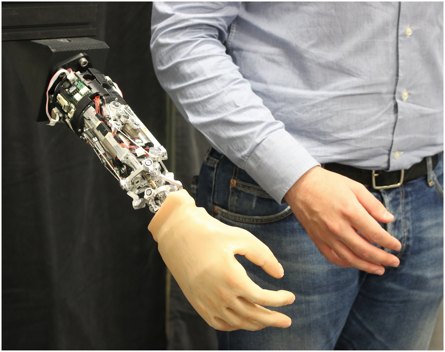
2. Design concept
The VS-Wrist features a hybrid serial-parallel architecture leveraging the redundancy of the actuation system and a non-linear elastic transmission to adjust the stiffness of the coupler. It comprises a 2 DoFs VS joint achieved through a Parallel Manipulator (PM) architecture complemented by an independent serial motor unit that is decoupled from the variable stiffness mechanism.
Figure 2(a) shows the overall architecture of the 2 DoFs VS joint. As discussed in Lemerle et al. (2021), its leg kinematics draws inspiration from the Omni-Wrist III outlined in Rosheim and Sauter (2002). However, the proposed design incorporates only three legs instead of four, and introduces substantial differences in the actuation system to enable the modulation of joint stiffness. Precisely, the 2 DoFs VS joint integrates a supplementary actuator and a non-linear elastic mechanism in its design to transmit the motion of each motor to the first joint of each kinematic chain. Panel (a) depicts a schematic architecture of the 2 DoFs VS joint integrated into the VS-Wrist. Its kinematic configuration is a parallel manipulator that achieves hemispherical movements of the coupler. Each leg, distinguished by a specific color, consists of a motor unit, a non-linear elastic transmission, and a kinematic chain of four revolute joints. Panel (b) displays the CAD of the VS-Wrist equipping a robotic prosthetic hand and highlights its DoFs. Panel (c) shows a close-up picture of the prototype.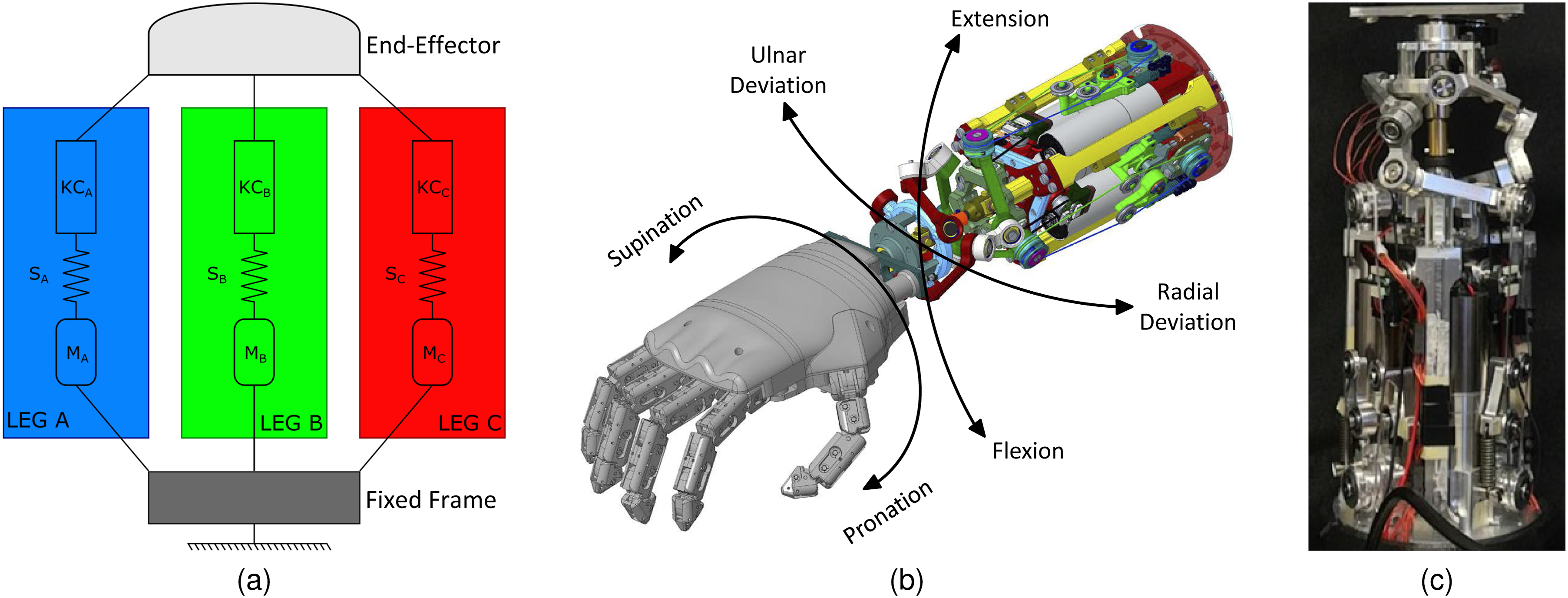
Figure 2(b) showcases the mechanical design of the VS-Wrist and delineates its DoFs. In this regard, the PM manages the radial/ulnar deviation (RUD) and the flexion/extension (FE) of the wrist, while the serial motor unit actuates the device along the pronation/supination (PS) axis. Unlike the human wrist, this latter motor unit only rotates the hand, rather than the entire forearm.
The VS-Wrist boasts an innovative mechanical structure that embodies part of the system intelligence. Typically, an n DoFs VS joint would necessitate 2n motors to control its position and stiffness. By utilizing a PM, it becomes possible to modulate joint stiffness using internal torques, requiring only three motors to control two positional DoFs and leaving one DoF dedicated to overall stiffness regulation. Consequently, the PM architecture achieves a two DoFs VS joint with the minimum possible number of motors, resulting in a compact and lightweight device. This design choice aligns with the human mechanism of muscular impedance regulation, where muscular cocontraction predominantly modulates the compliance ellipsoid dimensions, while the orientation of its axes essentially depends on posture (Ajoudani et al., 2018; Lemerle et al., 2021).
3. System analysis
To investigate the behavior of the device, we commence the kinematic analysis by considering the PM alone. Subsequently, we incorporate the effect of the serial motor unit, given that its rotation does not impact the PM kinematics. We define the reference coordinate frame {S
b
} = {O
b
, X
b
, Y
b
, Z
b
}, fixed to the base of the wrist, and {S
e
} = {O
e
, X
e
, Y
e
, Z
e
}, attached to the coupler. As shown in Figure 4, their origins (O
b
and O
e
) are located at the center of the base and coupler, respectively. The X-axes point upwards, the Z-axes point to the right, and the Y-axes are determined by the right-hand rule. The pose of the end-effector with respect to (w.r.t.) the fixed frame {S
b
} can be parametrized by the vector
We define the homogeneous transformation matrices
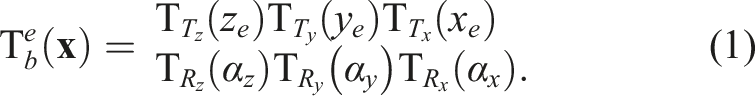
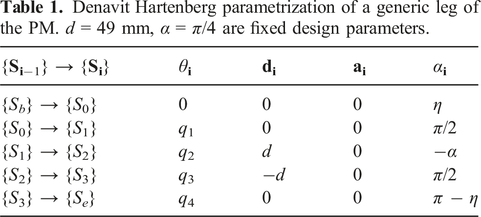
The transformation matrix Definition of the local reference coordinate frames of a generic leg according to the Denavit Hartenberg convention. d, η, and α are fixed design parameters.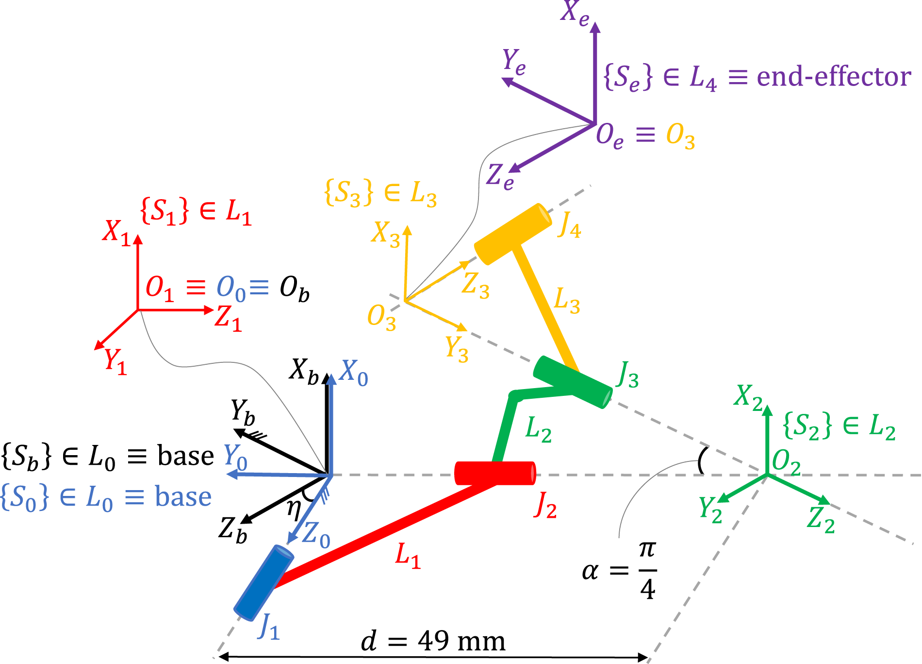


3.1. Pronation/supination transmission kinematics
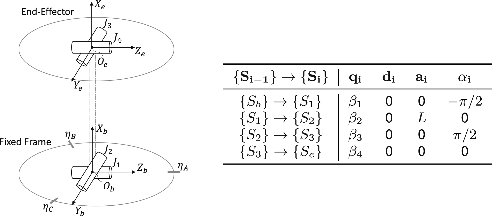
The PS motor transmits motion to the end-effector through a kinematic chain featuring two opposed Universal Joints (UJs) with rotation centers located at O
b
and O
e
. Figure 4 illustrates the schematization of the PS kinematic chain and reports its Denavit Hartenberg parametrization. Therefore, the UJs angles Schematic representation of the PS transmission. Each UJ is represented with two perpendicular and incident revolute joints, positioned at the center of either the fixed base frame or the coupler. Note that the two UJs are 90° out of phase to counteract the changing angular velocity of the driving shaft introduced by the lower UJ. The table on the right summarizes the Denavit Hartenberg parametrization of the kinematic chain. 
To solve the Inverse Kinematics (IK) of the PS mechanism, we exploit that the position of the coupler is independent of β3 and β4, and thus
Solving (5) yields β1 and β2 as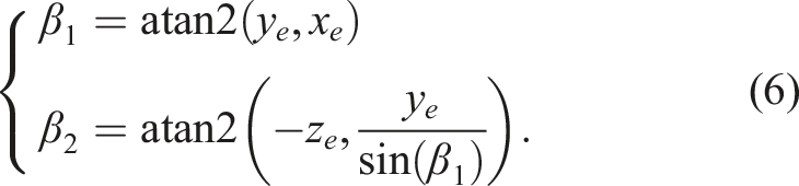
Finally, we equate 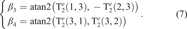
Due to the PM kinematics, the angles of the UJs are pairwise equal (i.e., β3 = β2 and β4 = β1). These findings can be utilized for detecting non-idealities in the PM kinematics or for system calibration purposes. The various panels depict the nominal range of motion of the 2 DoFs VS joint, illustrating the kinematic behavior of the system using the inverse kinematic model. Panels (a) to (e) represent motion around the Y
b
-axis, while panels (f) to (j) showcase a revolution around the Z
b
-axis (from π/2 to −π/2).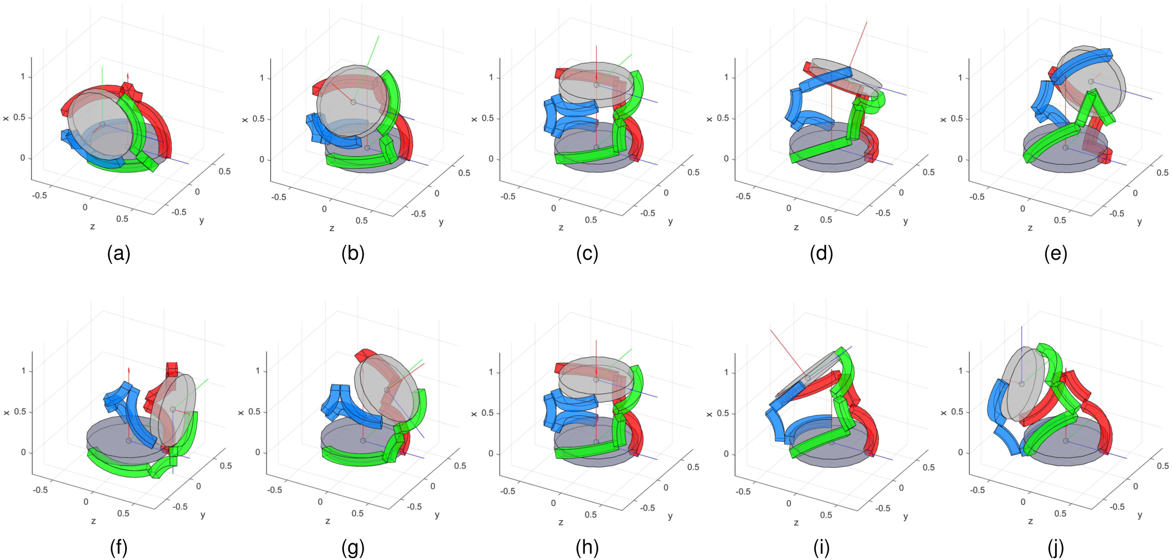
3.2. Single leg forward kinematics
The transformation matrix
Equating these two matrices and solving for 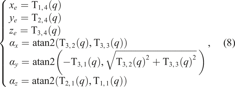
3.3. Inverse kinematics
Given the pose of the end-effector 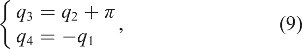
3.4. Parallel mechanism forward kinematics
By equating the transformation matrices obtained using the joint angles of different legs, it is possible to derive all the joint variables of a single kinematic chain as a function of the sole sensorized joint angles, which are the first ones of each leg. Computing x
e
and y
e
as functions of the joint angles of alternatively legs A and B yields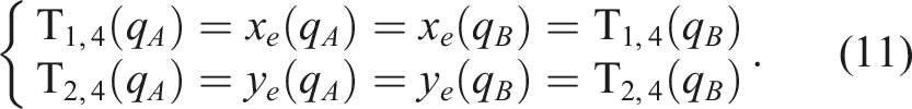
Aligning the fixed base frame with the first local frame of leg A (hence η
A
= 0, η
B
= 2/3π, and η
C
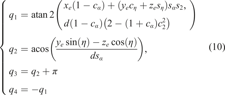
= 4/3π) and using (9), it is possible to solve the first equation of (11) to obtain
Since the encoders measure
3.5. Static equilibrium
To solve the static equilibrium of the PM, we open the kinematic chains at their last joints and impose the equilibrium of the end-effector subject to the external wrench and the reaction forces from the coupling joints. We then enforce the equilibrium of each leg, considering the previously computed reaction forces. This procedure, reported in detail in Appendix A, yields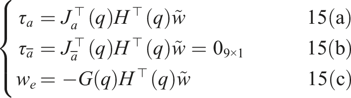


4. Elastic transmission mechanism
The elastic transmission mechanism, shown in Figure 6, employs an antagonistic setup of linear springs, tendons, and pulleys to achieve non-linearity thanks to their geometric configuration. To derive the output torque delivered by the elastic transmission, first, we compute the elastic energy stored in the springs as a function of the lever angle γ, obtaining Schematic representation of the non-linear elastic transmission mechanism. The top-left plot depicts the output torque (blue line) as a function of the deflection δ within the nominal range of motor torque (red lines).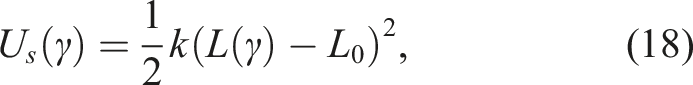

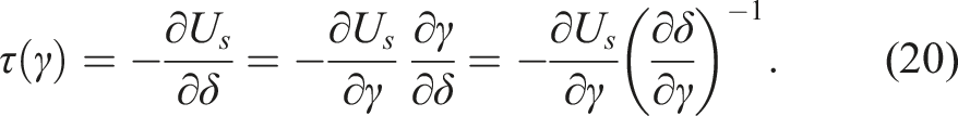
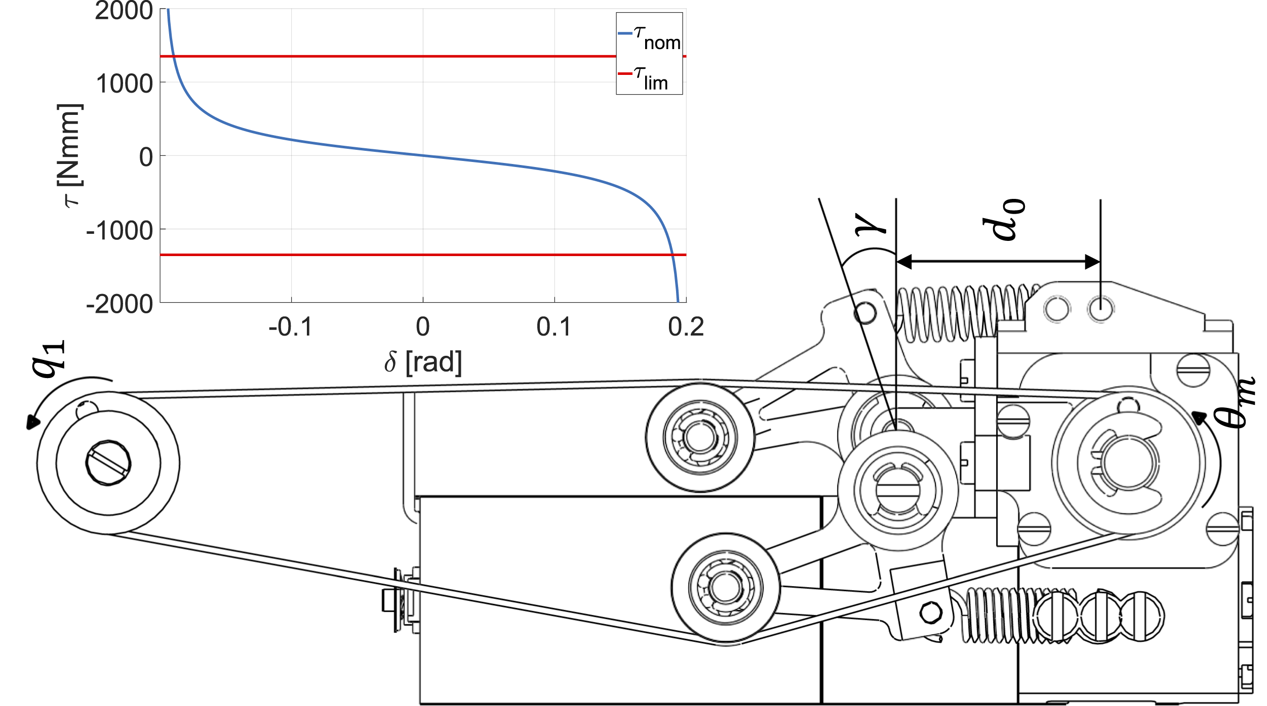
The relationship δ(γ, L t ) can be found by imposing the conservation of the tendon length L t , as outlined in Appendix B. Therefore, given δ from the encoder measurements and assuming L t is known by design, we can compute γ, and subsequently deduce the actuated torque.
To determine the stiffness of the elastic transmission K, it is sufficient to differentiate (20), yielding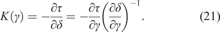
5. Hardware description
5.1. Mechanical hardware
Figure 7 shows the CAD of the VS-Wrist along with its overall dimensions. The fixed frame, depicted in red, has a diameter of 70 mm, while the coupler, shown in yellow, has a diameter of 60 mm. The total length of the device is 170 mm, and its weight is 1110 g. These dimensions align with the average sizes of a human wrist and forearm as per NASA (1995) and Damerla et al. (2022). CAD of the VS-Wrist. Each color highlights a different macro-component: red for the fixed frame, blue for the 2 DoFs VS joint motor units, green for the elastic transmission mechanism, magenta for the kinematic chains, orange for the PS unit, and yellow for the coupler. Panel (a) offers a comprehensive 3D view of the device along with its dimensions. Panel (b) details the implementation of one leg and its VS unit, while panel (c) showcases the PS unit.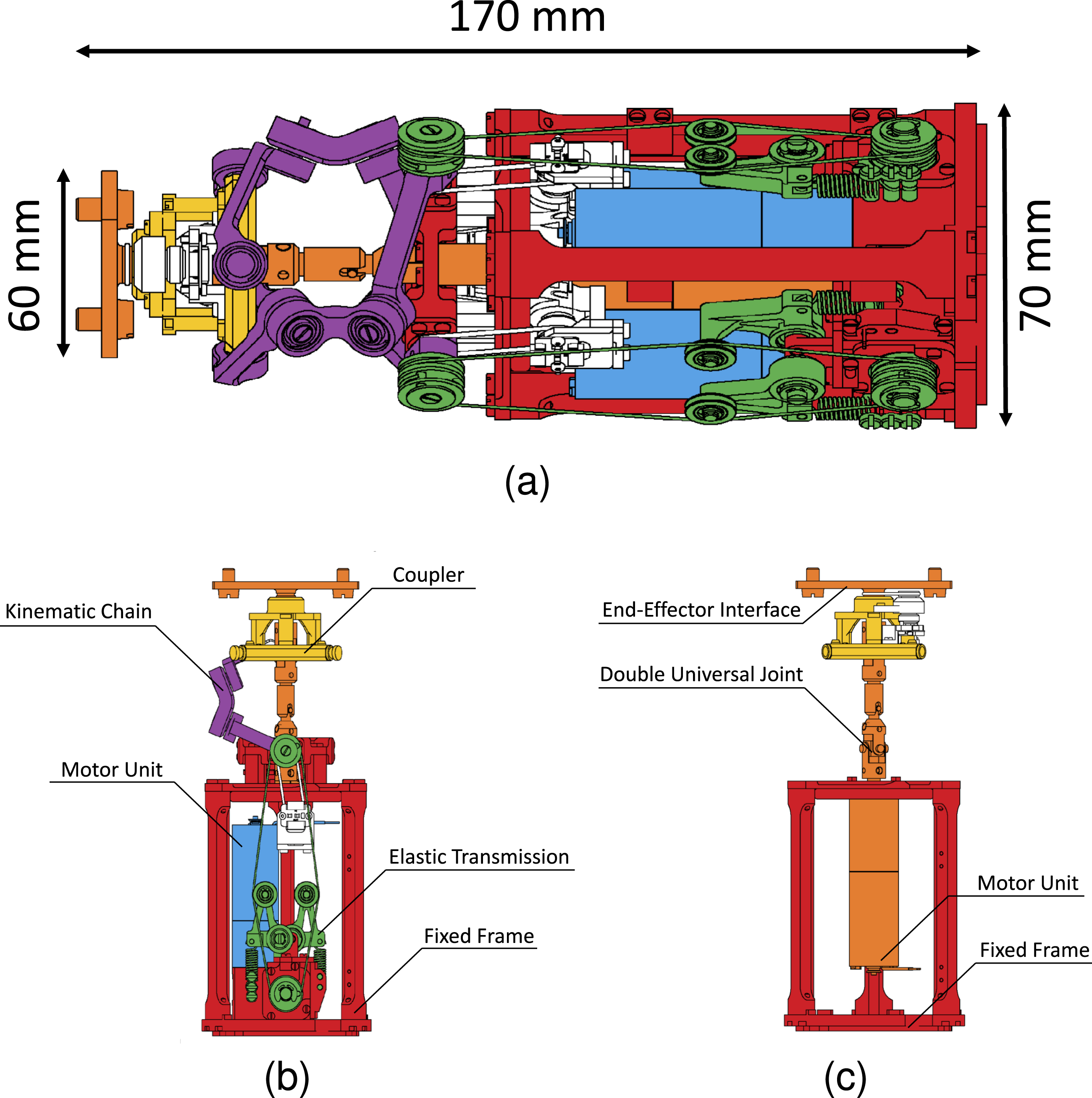
The VS joint features three identical sides composed of the serial arrangement of a motor unit (in blue), a non-linear elastic transmission (in green), and a kinematic chain of four non-coplanar revolute joints (in magenta). The motor unit comprises a Maxon DCX19S GB KL 12V motor, its associated gearbox, and a low-efficiency worm gear transmission to ensure the non-backdrivability of the system. Thanks to this design choice, the springs can apply constant forces to maintain high stiffness levels or balance static loads without power consumption. The resulting transmission ratio is 420, with an efficiency of 0.28. The maximum continuous torque deliverable to the gearbox output shaft is 1351 Nmm, while the maximum intermittent torque is 3883 Nmm. The nominal power consumption of each motor is 16 W, but since the actuation is non-backdrivable, the power demand is negligible when the wrist is not moving actively.
The kinematic chains, made of aluminum alloy Ergal 7075-T6, evenly distribute around the fixed frame. To assess the robustness of the device, we performed a FEM analysis of the kinematic chains under maximum load conditions. Figure 8 illustrates the magnitude of the displacement and von Mises stress of the first link when static equilibrium is reached under an external weight of 5.2 kg. Figure 8(a) shows that the maximum displacement of the link is restrained and approximately located in the middle section. Figure 8(b) demonstrates stress concentration in a rounded corner and affirms that the kinematic chain withstands the maximum load condition as the highest stress remains below the yield strength of the material σ
Y
= 503 MPa. The characteristic length d = 49 mm and angular deviation α = π/4 are carefully selected to prevent internal collisions between different legs and attain the desired workspace. The impact of these design parameters on the system workspace and compliance was previously examined in Lemerle et al. (2021). Additionally, Chang-Siu et al. (2022) provide a manipulability analysis assessing wrist dexterity while using a terminal device. FEM analysis of the first link of the parallel manipulator under maximum load condition. Panel (a) reports the magnitude of the displacement, and panel (b) shows that the von Mises stress remains below the yield strength of the material (σ
Y
= 503 MPa).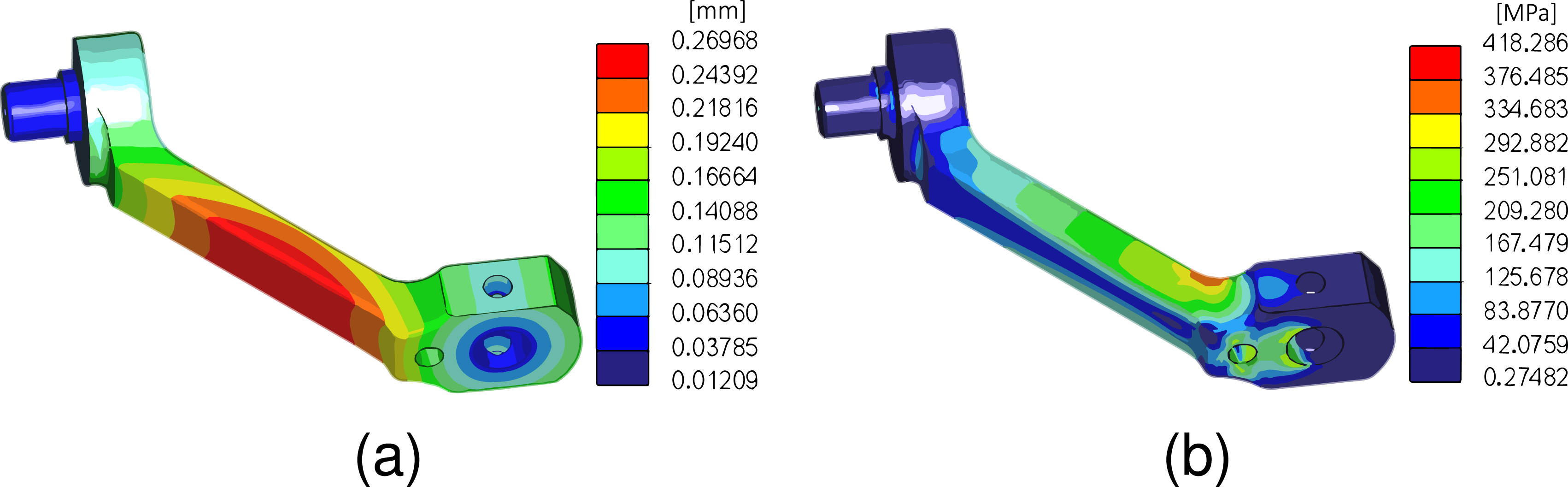
The elastic transmission mechanism achieves VS by adjusting the spring preload. For this purpose, one end of each spring is fixed to the frame, while the other end attaches to the lever arm mechanism that regulates the tension of the tendons. The elastic elements employed are the extension springs T31320 from MeterSprings, and the tendons are crafted using Liros DC120 from Unlimited Rope Solutions. A traction machine pulled the cables at 90% of their maximum tolerated tension to ensure that their length remains consistent during the regular operation of the wrist.
The PS actuator features a planetary gearbox with a transmission ratio of 168:1, efficiency of 0.65, maximum continuous of 1204 Nmm, maximum intermittent torque of 2000 Nmm, and a power consumption of 16 W. Figure 7(c) illustrates the mechanical implementation of the PS unit. The double UJ structure compensates for parallel misalignment and non-constant velocities between the driving and driven shafts. Importantly, the transmission is independent of the VS unit, meaning this motor does not modify the stiffness of the joint.
5.2. Electronic hardware
The device incorporates the NMMI electronics detailed in Della Santina et al. (2017b). Four independent PID controllers regulate the position of the DC motors, relying on feedback from four rotary magnetic encoders that measure the angle θ of the gearbox output shafts. Three additional encoders measure the first joint angle q1 of each kinematic chain. The 12-bit programmable encoders AS5045 from Austriamicrosystems provide angular positions with a resolution of 0.09°. Four motor drivers MC33887 from NXP Semiconductors independently drive the DC motors. The current flowing to the motor is regulated at 1 kHz by modulating the duty cycle of a 20 kHz PWM signal. The Programmable System-on-Chip (PSoC) 5LP CY8C58LP from Cypress manages the PID controller at a frequency of 1 kHz. The embedded microcontroller is a 32-bit Arm Cortex-M3 core plus DMA. A daisy-chain connection allows various boards to communicate and share power from a single DJI TB47 (4500 mAh) battery. The PSoC connects to the computer via micro-USB, and communication is handled through the RS485 serial protocol.
6. Control architecture
To validate the effectiveness of the proposed hardware without compromising the inherent compliance of the system (Della Santina et al., 2017a), we opt for a simple open-loop controller. This control strategy regulates the motor positions based solely on kinematic considerations, remaining independent of the characteristics of the non-linear elastic transmission. The control architecture, schematized in Figure 9, consists of a position controller and a stiffness controller, both decoupled and operating in parallel. Scheme of the control architecture. A simulink model sets the position and stiffness references in real-time, communicating with the electronic hardware through the NMMI framework. Bidirectional communication ensures that encoder measurements are available to the user within the simulink environment.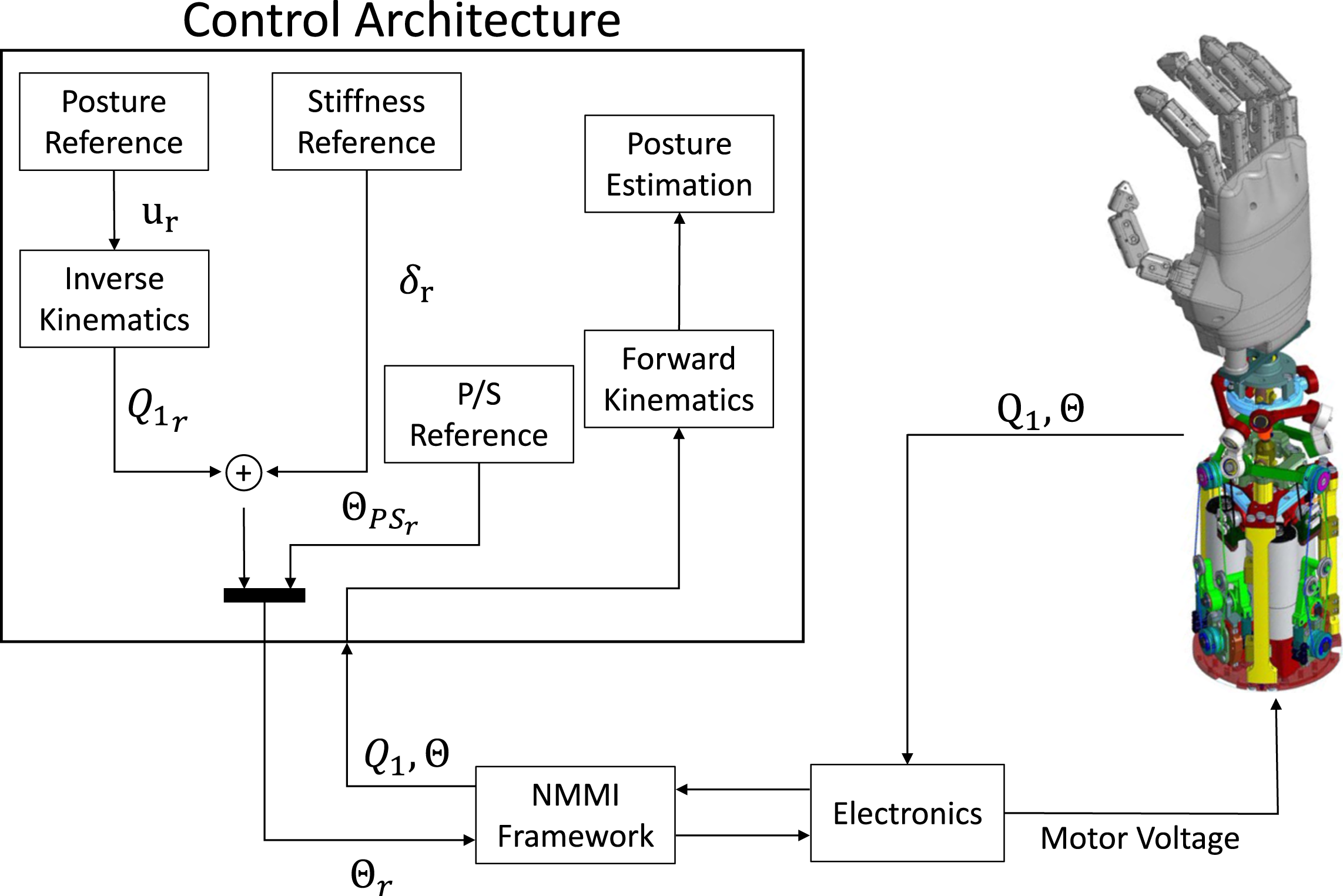
6.1. Posture control
The posture controller capitalizes on the insight that the system naturally tends towards static equilibrium by minimizing the elastic energy stored in the springs. In the absence of external or internal loads, this equilibrium occurs when the deflection δ is null. Consequently, the angular position of the first joint follows the corresponding motor angle.
Given a desired pose of the wrist in minimum parametrization u
r
, (10) provides the corresponding first joint angle of each leg 
Since the serial motor unit directly acts on the PS of the wrist, this DoF is independently regulated using a conventional proportional control loop.
6.2. Stiffness control
As described in Section 3.5, the internal forces delivered by the actuation system τ s = λN0(u) govern stiffness regulation. Although the base of the actuated internal torques relies exclusively on the kinematics of the manipulator, deriving the motor angles that yield these torques requires perfect knowledge of the elastic transmission model. However, non-modeled phenomena, such as hysteresis, tendon stretching, and manufacturing variability, limit the reliability of the derived model.
For simplicity, we assume all the VS units to be identical, and we neglect the variations of N0 with posture, considering it constant at the value achieved when the wrist is in the central position. Then, we refine this approximation through a calibration procedure described in Section 7.2. We define the motor references that modulate the stiffness of the coupler 
6.3. Combined control
Integrating stiffness and posture control, the device moves to the commanded posture while the VS units maintain the desired preload. Due to the non-backdrivability of the actuation, external wrenches acting on the wrist do not influence the motor output shaft. As a result, the device consistently displaces according to the commanded stiffness, leveraging the embedded elasticity. To concurrently manage both joint stiffness and position, we assume the two controllers to be perfectly decoupled. Consequently, we define the motor reference angles as
Finally, a simple proportional control yields the commanded motor angle.
6.4. Hardware implementation
The hardware implementation of the high-level controller, schematized in Figure 9, was conducted in MATLAB Simulink using the NMMI framework (Della Santina et al., 2017b). This setup enables real-time bidirectional communication between Simulink and the electronic components of the VS-Wrist. To account for delays arising from the communication protocol and computations, the frequency of the Simulink diagram was reduced to 200 Hz, ensuring real-time execution.
7. System calibration and characterization
We calibrate the system to address errors arising from manufacturing tolerances and other un-modeled phenomena. The limitations of the prototype, stemming from non-nominal behavior, are summarized and discussed in Section 9.1.
7.1. Experimental setup
We measure the posture of the wrist using a Vicon 2 motion capture system consisting of 12 optical cameras and 14 reflective markers.
With the aid of custom 3D-printed supports, three sets of markers are affixed to the base frame, the coupler, and the end-effector, respectively (see Figure 10). The camera data are sampled at a frequency of 100 Hz and exported to Matlab for post-processing. Utilizing the marker trajectories, we reconstruct the absolute position and orientation of the reference frames {S
b
} and {S
e
} to compute the posture of the end-effector Panel (a) shows the employed marker set, and panel (b) displays its reconstruction conducted by the motion capture system within the Vicon Nexus environment.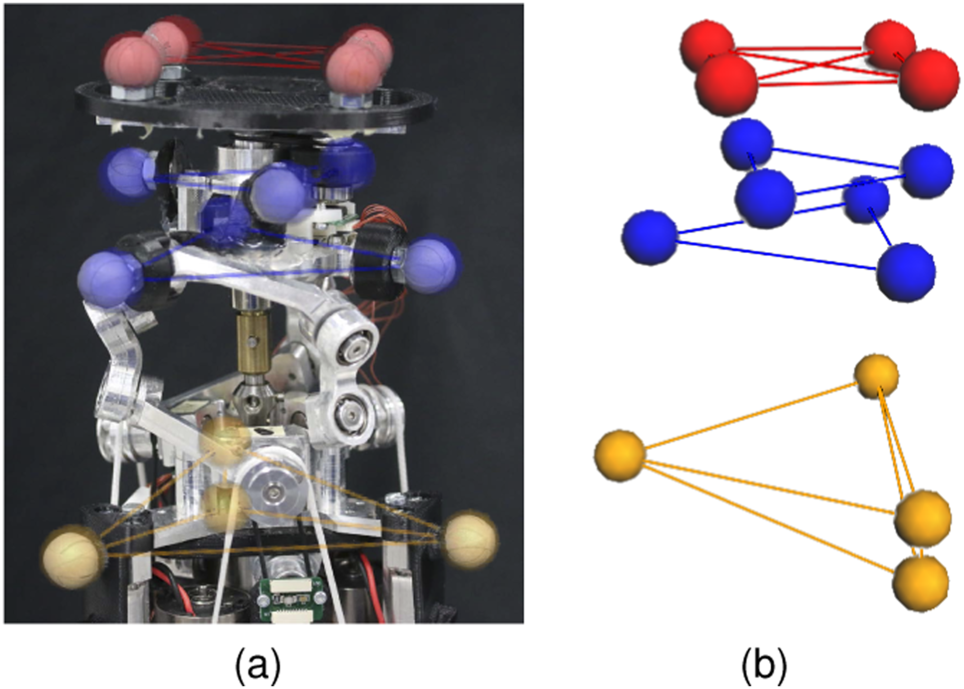
7.2. Stiffness control calibration
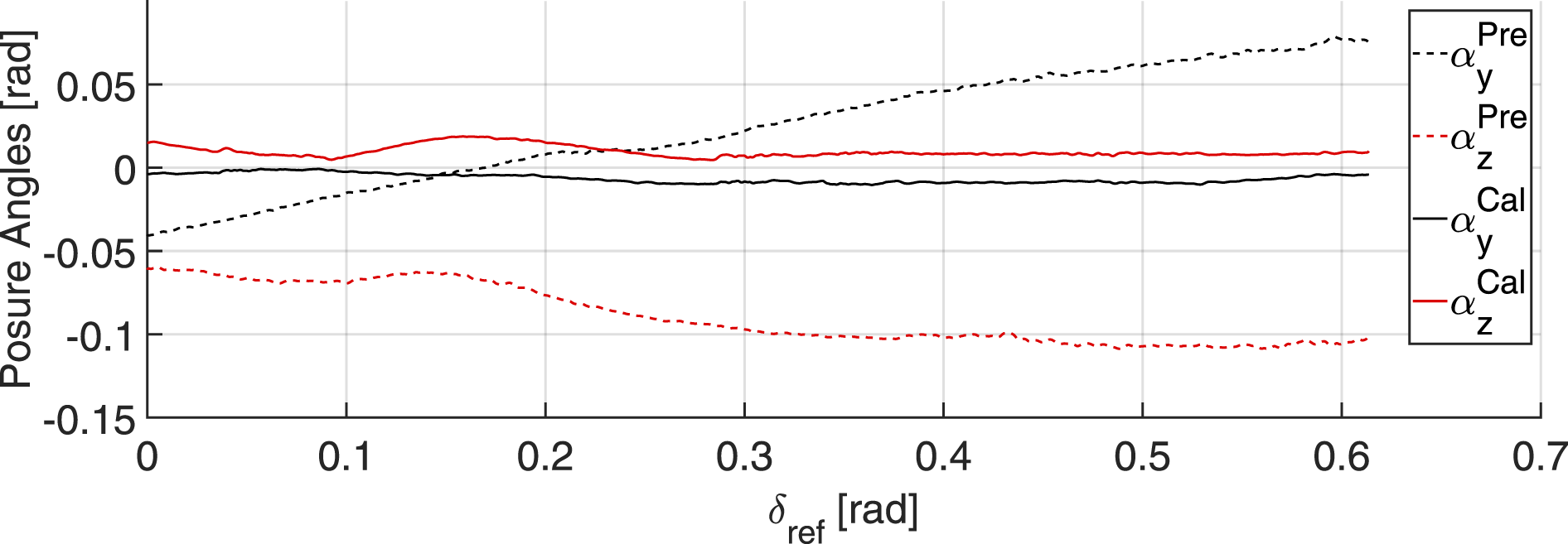
Although the system can theoretically modulate its stiffness without moving the end-effector, we observe a slight deviation of the coupler when controlling the prototype based on the nominal model (see Figure 11, dashed lines). To address this issue, we fit the experimental data to determine a compensation command that mitigates the observed posture drift using least squares optimization. Subsequently, we adjust the reference posture angles as Calibration of the stiffness controller. The graph demonstrates that, prior to calibration, a pure stiffness command induces changes in the wrist posture due to manufacturing variability (dashed lines). Repeating the experiments after applying the compensation command validates that the proposed calibration process effectively mitigated this undesired phenomenon (continuous lines).
7.3. Combined control calibration and characterization
To characterize the behavior of the posture controller, we begin by testing each DoF separately using step and sine wave posture references. Subsequently, we combine all DoFs to estimate the RoM of the device. Each trial is repeated three times for each of the six tested stiffness configurations.
Figure 12(a) demonstrates how the device tracks a sinusoidal reference at different stiffness configurations. Notably, the RoM of the device slightly reduces as the stiffness grows. At maximum stiffness, the device achieves ±0.85 rad for α
y
, and [−0.8, 0.9] rad for α
z
. The proportional controller provides swift and accurate pursuit of motor reference, with an average RMSE (θ) = 0.02 rad. However, the effective posture of the prototype deviates from the sinusoidal reference by approximately 40% (RMSE (u) = 0.35 rad), exhibiting undesired cross-axis movements. Characterization of the kinematic behavior of the device. Each color represents a different stiffness configuration (increasing from S1 to S6). Panel (a) shows the device tracking sinusoidal references, acting on a single axis per time. Panel (b) shows the experimental RoM of the prototype obtained by sampling its 2D workspace with a grid.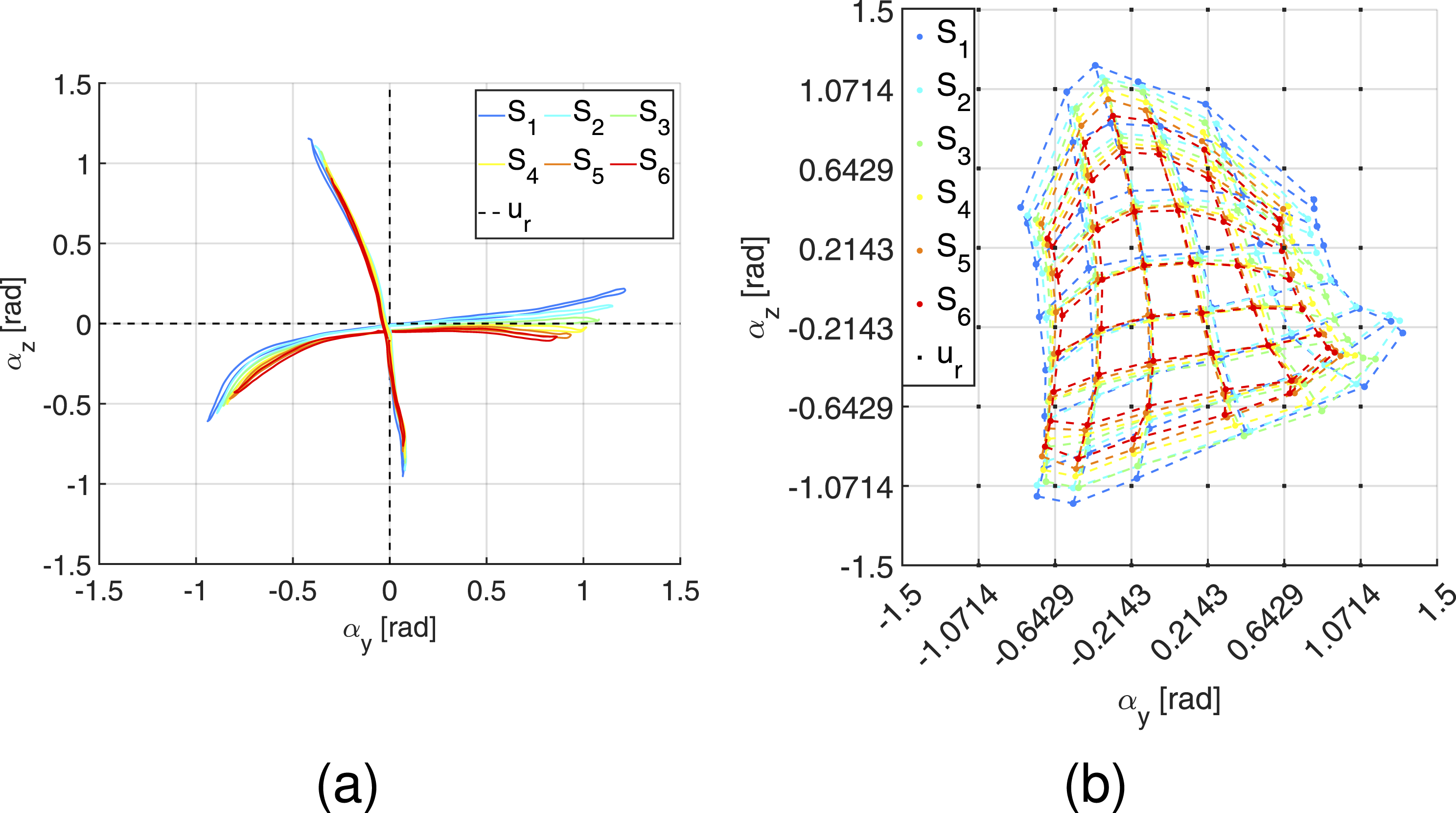
We sampled the 2D-RoM of the VS joint with a grid and acquired static measurements of the device posture, combining movements on both planes at various stiffness configurations. Figure 12(b) portrays the RoM of the prototype along the FE and RUD DoFs, showing that the workspace of the device is smaller than the nominal one and reduces as the stiffness of the wrist increases. The average standard deviation of the posture among different repetitions of the same trial is very low (σ u = 0.04 rad), indicating precise and reproducible control. However, accuracy is compromised (RMSE (α y ) = 0.25 rad, RMSE (α z ) = 0.50 rad) due to the use of open-loop control based on the nominal model, resulting in significant discrepancies between the actual and controlled positions.
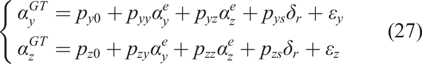
Based on the identified kinematic behavior, we developed a linear map that adjusts the posture reference by leveraging experimental data. Given a desired posture 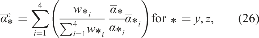
7.4. Posture reconstruction calibration
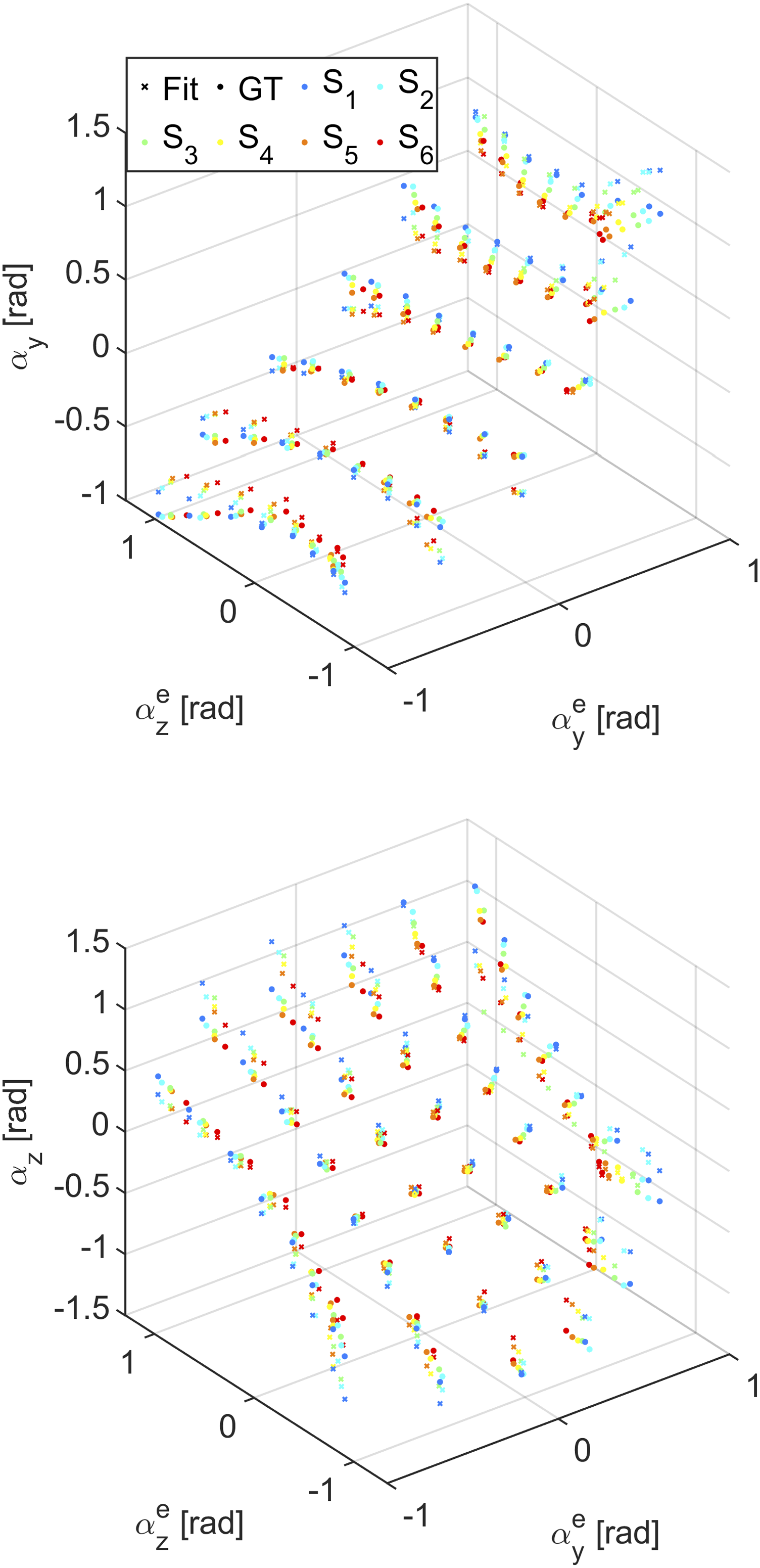
Wrist posture reconstructed through multivariate linear regression. Each color corresponds to a distinct stiffness configuration (increasing from S1 to S6). Crosses indicate the posture reconstructed by the algorithm, while dots represent the posture measured with motion capture, assumed as the ground truth.
8. Experimental validation
To validate the control strategy, we replicated the experiments detailed in Section 7 after applying the calibration procedure.
Figure 14(a) reports the posture of the device while chasing sinusoidal references acting, one per time, on both DoFs. To assess the accuracy of the posture pursuit, we applied the Linear Fit Method (LFM) as in Iosa et al. (2014). Precisely, we fit the posture reference with a linear model of the effective posture. Consequently, if the tracking is accurate, the linear coefficient will be close to 1 and the bias close to 0. The results of the linear fit, resumed in the upper half of Table 3, confirmed that the posture of the device is an accurate replica of the desired pose. Additionally, we applied the LFM to compare the posture estimated using the encoders with the measurements of the motion capture system. The results, presented on the right side of Table 3, confirmed that the posture is reconstructed accurately. Characterization of the device kinematic behavior after system calibration. Each color corresponds to a distinct stiffness configuration (increasing from S1 to S6). Panel (a) shows the device chasing sinusoidal references, acting on a single axis at a time. Panel (b) shows the experimental RoM of the prototype, acquired by sampling its 2D workspace with a grid.
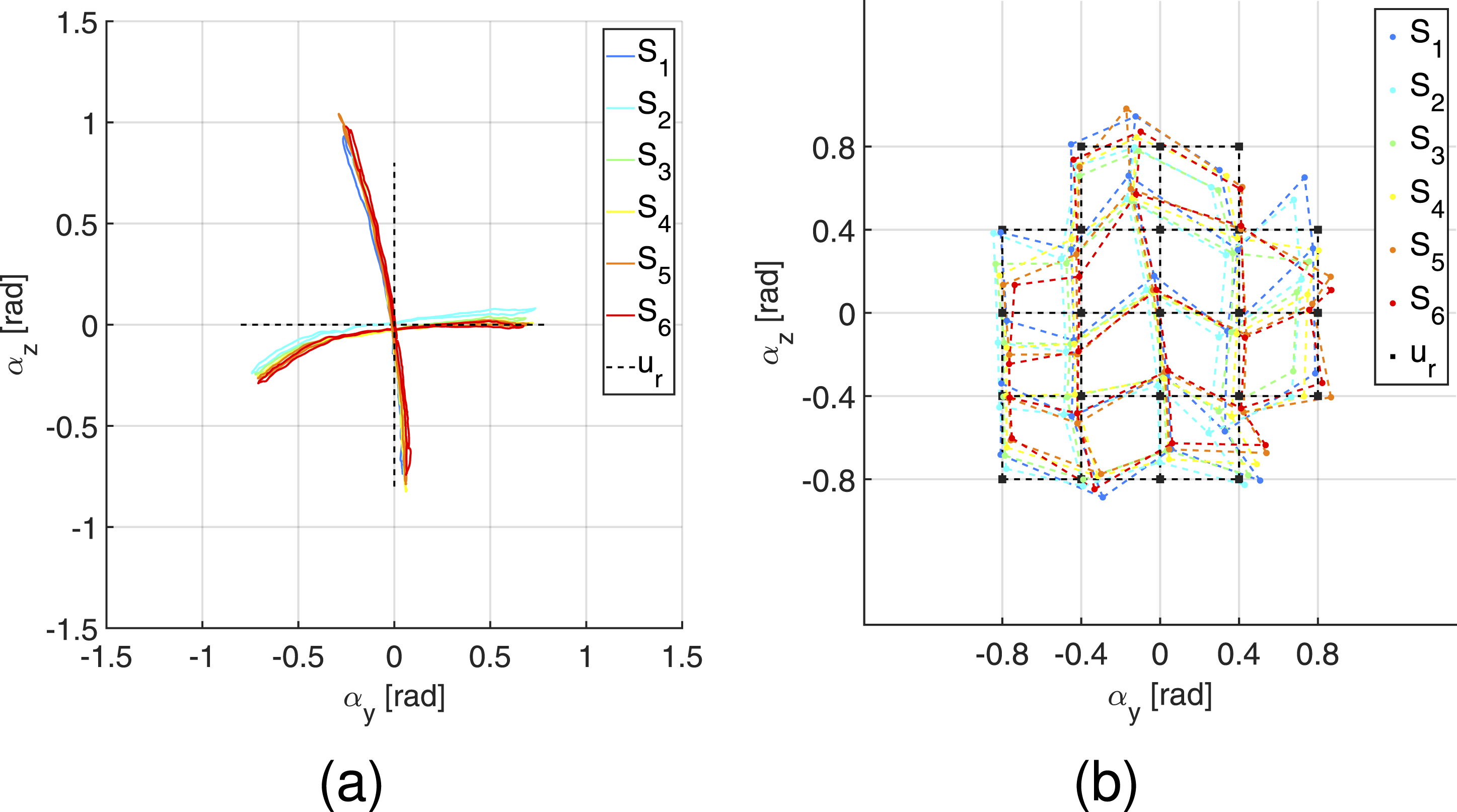
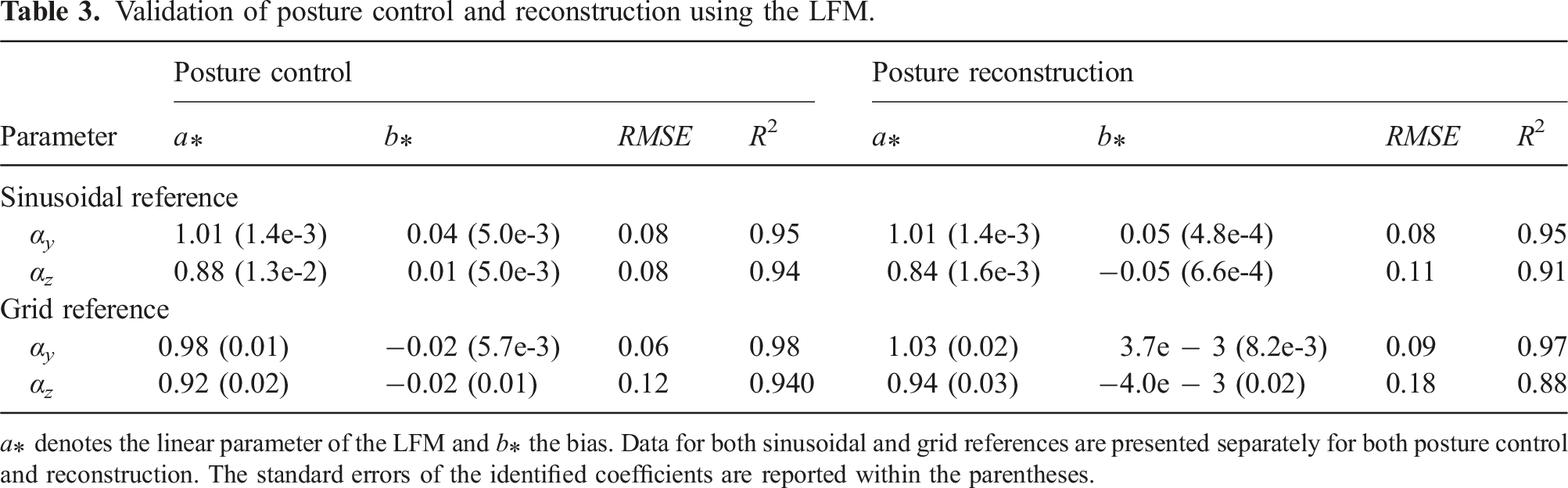
Figure 14(b) shows the performance of the VS joint tracking simultaneous references on both axes. Similarly, we applied the LFM to evaluate the accuracy of posture tracking and estimation. The identified parameters, reported in the lower half of Table 3, affirmed the effectiveness of the calibration procedure, validating both posture control and reconstruction strategies. Notably, the experimental data did not reveal any correlation between the commanded stiffness and posture tracking and reconstruction performance or the workspace.
The PS unit achieves very precise (σ PS = 0.01 rad) and accurate control (RMSE (θ PS ) = 0.02 rad), and its RoM is unconstrained (±π).
The output speed of the device is computed using step references that span the RoM of each individual DoF at minimum and maximum stiffness configurations. The wrist speed decreases as the stiffness increases, except for the PS, as its mechanical transmission is decoupled from the VS units. The average output speed ranges from 4.0 to 8.4 rad/s for the FE and from 3.0 to 6.3 rad/s for the RUD, while the PS average speed is 10.8 rad/s.
8.1. Variable stiffness ability
The VS-Wrist exploits its redundant elastic actuation to vary the stiffness of the coupler, adapting to tasks of different natures. To demonstrate this capability, we replicated the experiment depicted in Figure 12(b) after attaching a load to the end-effector. During this experiment, the VS-Wrist is hung upside-down on a fixed frame, as shown in Figure 15. An external load of 640 g is affixed to the coupler at a distance of 78 mm. Therefore, the force of gravity applies a known external wrench that varies with the posture of the wrist. To quantify the stiffness, we assume that it remains constant during each trial. This assumption holds Experimental setup employed to quantify the variable stiffness ability of the device. The VS-Wrist is suspended upside-down from a fixed frame, with a mass attached to the coupler. The external load causes the coupler to shift its equilibrium configuration coherently with the commanded stiffness, exploiting the embedded elasticity.

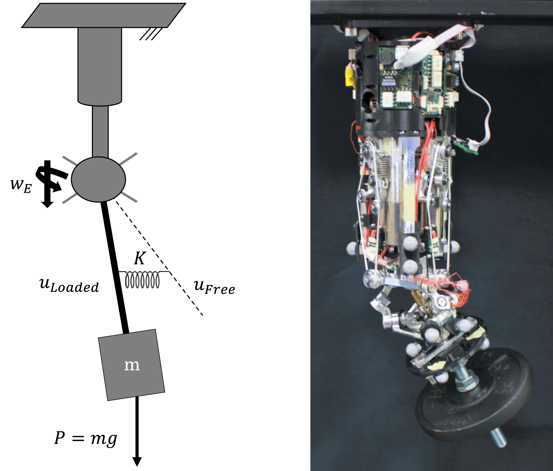
Figure 16(b) shows the device tracking circular trajectories under both loaded and unloaded conditions at various stiffness configurations. The device stiffness dictates its response to external perturbations, with higher stiffness resulting in smaller differences between trajectories in loaded and unloaded configurations. Accordingly, in Figure 16(b), the circles reduce their size inversely proportional to the commanded stiffness when the load is applied. Experimental evaluation of the device variable stiffness ability. Panel (a) reports the posture of the VS joint as it explores its 2D-RoM at various stiffness configurations (increasing from S1 to S6) while a load is attached to the end-effector. Panel (b) shows the device tracking circular trajectories at four different stiffness levels (increasing from S1 to S4) in both unloaded (dashed lines) and loaded (continuous lines) configurations. The radii of the latter circles are proportional to the stiffness, which defines the resistance to external perturbations.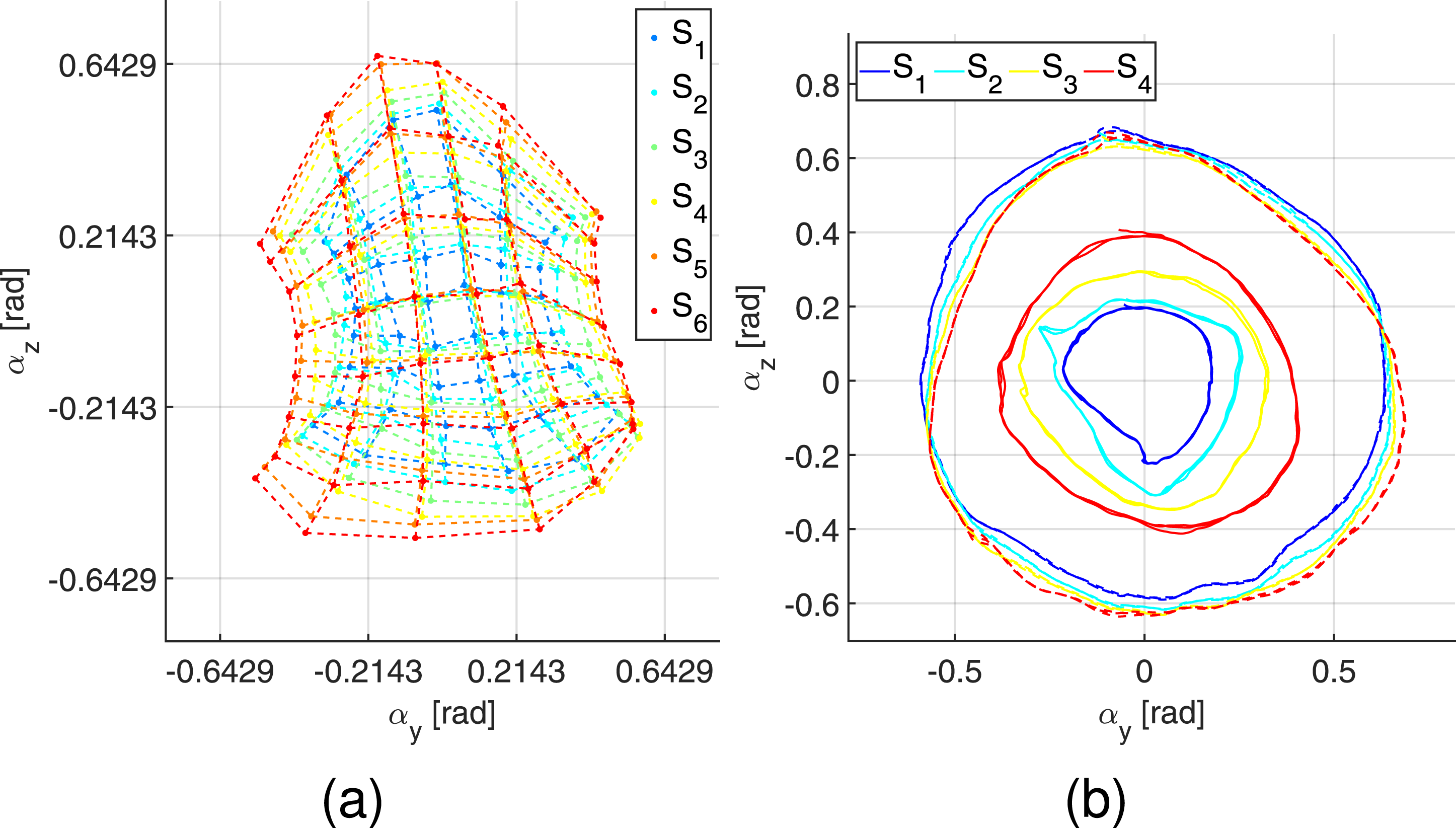
8.2. Qualitative evaluation of motion and stiffness behavior
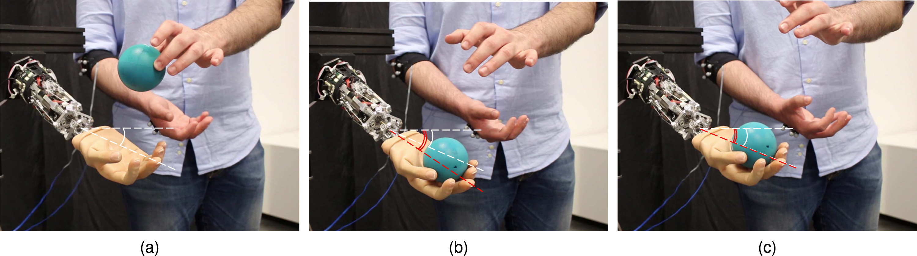
To provide a more intuitive representation of the device operating principle and emphasize its anthropomorphism, we map the posture and stiffness of a human operator’s wrist into command signals for the robotic device. The reference posture is captured with cameras through a marker set attached to the user’s forearm and hand. Furthermore, we registered the operator’s myoelectric activity of the wrist flexor and extensor to measure their cocontraction, which we related to the desired stiffness of the VS-Wrist, similarly to Capsi-Morales et al. (2020). To do so, we employed two commercial electrodes 13E200 from Ottobock, which are commonly used to control prosthetic limbs. Figures 17 and 18 summarize the outcome of the experiments with some frames of the video attached as supplemental material to this paper. Figure 17 shows that the spring preload is modulated through muscular cocontraction while the device tracks the operator’s wrist posture. Figure 18 proves that different stiffness configurations achieve various responses to external perturbations. Therefore, the variable stiffness should enhance task adaptability and environmental interactions. Photosequence capturing the VS-Wrist tracking the user’s posture and muscular cocontraction. The central graph displays the corresponding normalized EMG signals measured from a couple of antagonistic muscles of the user’s forearm, highlighting the muscular cocontraction C, which defines the stiffness reference of the robotic wrist. Each panel depicts a specific instant of the experiment and is associated with the corresponding EMG measurement. The panels on the right describe the functioning of the elastic transmission that achieves stiffness regulation. The bottom-right frame shows the device in the soft configuration, where tendon tension is low. The top-right panel portrays the VS-Wrist in the rigid configuration, matching the operator’s muscular impedance. Coherently, the tendons on one side of all VS units stretch to increase the stiffness. Response to external perturbation at different stiffness configurations. Visual feedback is provided by the angle formed between the segment from the center of the coupler to the middle finger and the horizontal plane. During the trial, the VS-Wrist holds a reference posture (panel (a), white lines) before being impacted by a ball in free fall. Due to variable stiffness, the device reaches different equilibrium configurations (red lines), as illustrated in panel (b) for the soft configuration and (c) for the rigid one.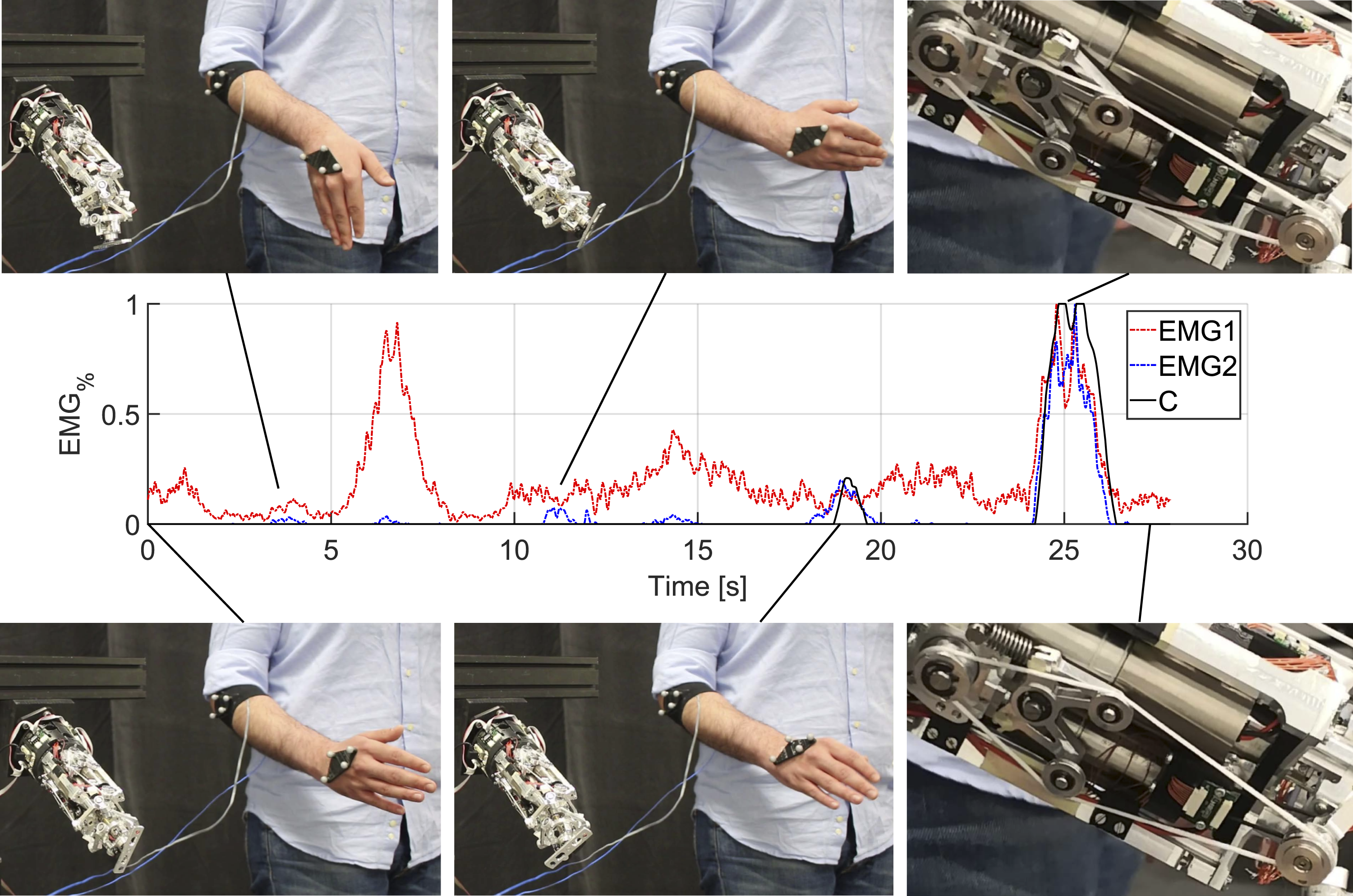
9. Discussion
The initial experimental phase revealed non-idealities that we addressed and mitigated through a calibration process. The calibration of the stiffness controller, compensating for VS unit asymmetry, successfully eliminated undesired movements associated with changes in joint stiffness. The combined control calibration enhanced posture accuracy by leveraging the experimental motion behavior, identified through grid sampling of the RoM. Undoubtedly, the absence of posture feedback within the control law induces a residual error in the end-effector trajectory. Conversely, our decision to prioritize a simple implementation not only maintains the intrinsic compliance of the device but also demands low computational power, making it well-suited for prosthetic applications. Moreover, the inaccuracy in tracking a desired posture becomes a minor concern in applications where a human operator closes the control loop, such as prosthetics or teleoperation.
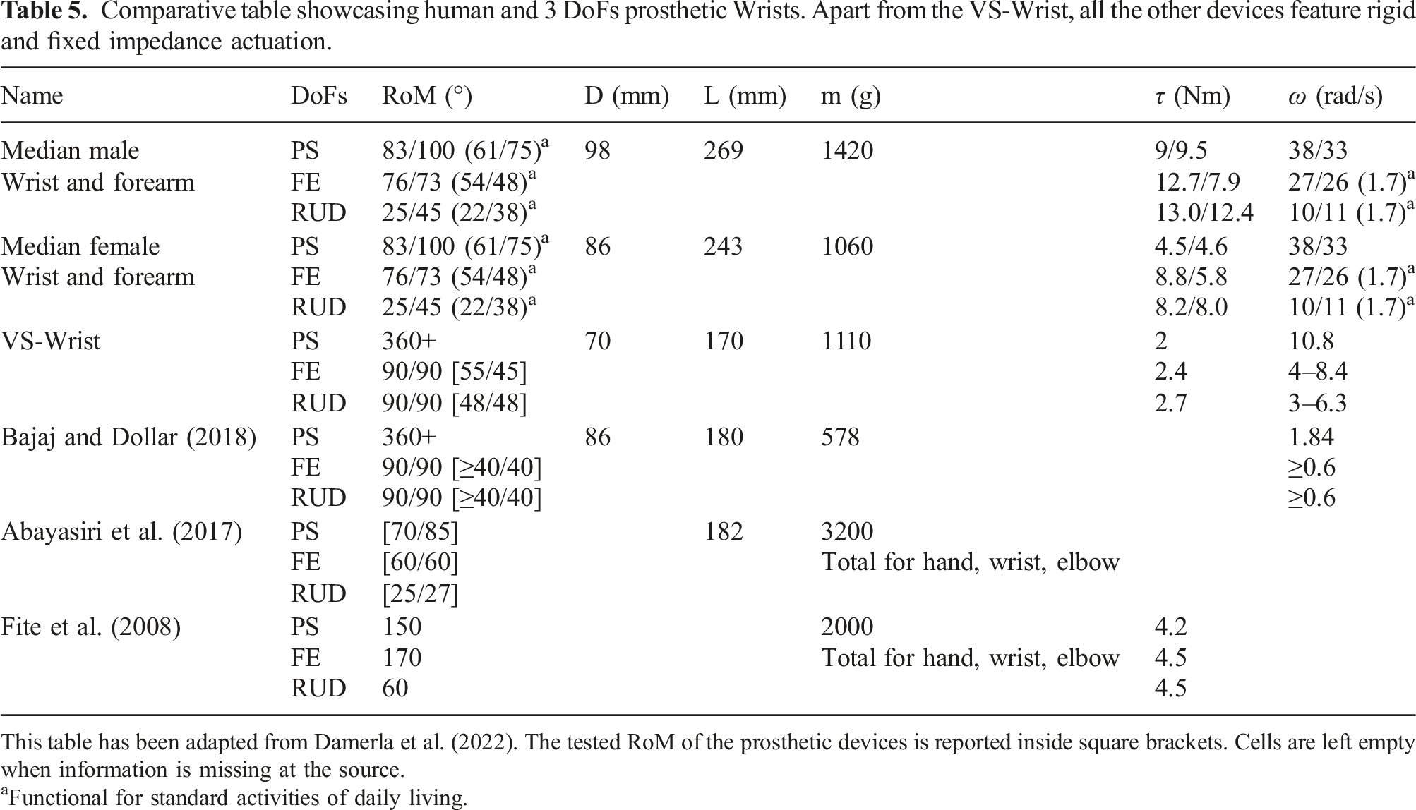
This table has been adapted from Damerla et al. (2022). The tested RoM of the prosthetic devices is reported inside square brackets. Cells are left empty when information is missing at the source.
aFunctional for standard activities of daily living.
9.1. Prototype limitations
We expect several mechanical refinements for the next release of the prototype. The current version exhibited limitations in both maximum payload and stiffness, primarily attributed to high manufacturing tolerances resulting in mechanical backlashes. For this reason, attempts to replicate experiments detailed in Section 8.1 with the wrist positioned horizontally were unsuccessful. The device could only sustain the payload at high stiffness levels and within a limited RoM, precluding the identification of its stiffness. Additionally, despite incorporating the functional RoM of the human wrist, the prototype workspace and accuracy were reduced due to non-nominal kinematics.
Although the VS-Wrist approximately matches half the size and weight of a human forearm, future designs should optimize its weight for enhanced user comfort. Furthermore, the prototype length may pose challenges in fitting most transradial amputees but could be suitable for transhumeral amputees.
As this paper presents our first prototype, certain aspects require refinement in both design and manufacturing before undergoing clinical trials. Nonetheless, with proper optimization, the proposed architecture holds promise for prosthetic applications, introducing innovative features such as variable stiffness and 3 DoFs movements. This makes it a significant contribution to the field of prosthetics, as the presented design has the potential to considerably enhance the dexterity and naturalness of upper limb prostheses, addressing the limitations of current commercial devices that predominantly feature passive, rigid joints with restricted DoFs.
10. Conclusion and future developments
This study addresses the challenge of modeling and controlling a variable stiffness 3 DoFs wrist featuring redundant elastic actuation. Its controllable stiffness and inherent compliance enable the device to interact safely with the environment, adapting to tasks of various natures. In the soft configuration, contact forces are minimized, while the device effectively resists external perturbations at high stiffness. The presented calibration procedure successfully compensated for the prototype deviations from its nominal model, ensuring precise posture control and reconstruction.
Optimizing the design and manufacturing processes is crucial to reduce mechanical backlash and augment the stiffness of the device. Attention must be directed towards minimizing the device weight, considering the potential discomfort for prosthesis users. Additional investigations into the robustness of the device are necessary to ensure proper functionality during extended use. Nevertheless, the VS-Wrist holds the potential to enhance the natural feel of existing bionic limbs by resembling the kinematic and compliant behaviors of its natural counterpart. Further quantitative analyses involving standard daily activities could provide valuable insights into assessing the morphological and functional similarities between the device and the human wrist.
Other developments of this work concern the mapping of user EMG signals into control commands for the prosthesis. While coordinated control of multiple DoFs remains an open challenge, recent advancements in neuroscience offer potential solutions for operating more complex prostheses.
Supplemental Material
Supplemental Material
Supplemental Material - Modeling and control of a novel variable stiffness three DoFs wrist
Supplemental Material for Modeling and control of a novel variable stiffness three DoFs wrist by Giuseppe Milazzo, Manuel Giuseppe Catalano, Antonio Bicchi, and Giorgio Grioli in The International Journal of Robotics Research.
Footnotes
Acknowledgements
The authors would like to thank Vinicio Tincani, Mattia Poggiani, Manuel Barbarossa, Emanuele Sessa, Marina Gnocco, Giovanni Rosato, and Anna Pace for their fundamental technical support given during the hardware implementation of this work. An additional thanks goes to Simon Lemerle for his work on the design concept of the device.
Declaration of conflicting interests
The author(s) declared no potential conflicts of interest with respect to the research, authorship, and/or publication of this article.
Funding
The author(s) disclosed receipt of the following financial support for the research, authorship, and/or publication of this article: This research has received funding from the European Union’s ERC Synergy Grant Agreement (810346) Natural BionicS, H2020 Programme under grant agreements ReconCycle (871352) and RePAIR (964854), and by the Italian Ministry of Education and Research (MIUR) in the framework of the FoReLab project (Departments of Excellence). The content of this publication is the sole responsibility of the authors. The European Commission or its services cannot be held responsible for any use that may be made of the information it contains.
Supplemental Material
Supplemental material for this article is available online.
Notes
References
Supplementary Material
Please find the following supplemental material available below.
For Open Access articles published under a Creative Commons License, all supplemental material carries the same license as the article it is associated with.
For non-Open Access articles published, all supplemental material carries a non-exclusive license, and permission requests for re-use of supplemental material or any part of supplemental material shall be sent directly to the copyright owner as specified in the copyright notice associated with the article.