
Abstract
This article proposes a deduction method of algebraic expression of static wrench-closure workspace boundary for planar 3-degree-of-freedom cable-driven parallel robots based on the antipodal theorem. Different from interval method and discretization approach, a more precise algebraic expression of workspace boundary can be obtained without undetermined region or costly computation burden to make the design process and optimization easy and feasible. In order to illustrate and study the conic characteristics of workspace boundary, a case study is conducted on a four-cable-driven 3-degree-of-freedom parallel robot. Simulation results show that the type of conic of boundary depends on the determinant of the specific deduced matrix and corresponds to which cable is collinear with the intersection line. In addition, the results also demonstrate that the boundary of workspace consists of the same type of two conics (i.e. ellipse, parabola, and hyperbola), and the region surrounded by these two quadratic curves is the smallest when the type of the border equation is parabola.
Introduction
Cable-driven parallel robots as a special parallel robot actuated by cables/wires have received more attention by researchers and engineering companies for their superior features in high acceleration/velocity 1 or large workspace for contour crafting construction/astronomical observation in the five-hundred-meter aperture spherical radio telescope (FAST) project.2–5 Some practical application designs such as fabrication prototype 6 and cable system for improving mobility (CaSIMo) 7 were proposed and studied as spatial redundantly actuated cable-driven robot and cable-suspended robot. The difference between these two types of cable parallel robots is that the latter has to take advantage of gravity of the end-effector and the load applied on it while the former one does not. Besides, the spatial cable-driven manipulator was also used in medical arm rehabilitation device because of its lightweight structure and ease of generating forces in all direction. 8
In literature, the workspace of cable-driven parallel robots is divided into two main categories: static workspace and dynamic workspace. Furthermore, static workspace can be distinguished into wrench-closure workspace (WCW), wrench-feasible workspace (WFW), force-closure workspace (FCW), and statically feasible workspace (SFW). (See studies by Voglewede and Ebert-Uphoff, 9 Verhoeven et al., 10 Duan and Duan, 11 and Tang et al. 12 for literature review.) On the other hand, dynamic workspace has a unique feature that the end-effector can controllably move beyond the static workspace.13,14
As for workspace determination as one of the fundamental issues of robotic analysis, a lot of researchers had proposed several methods to solve it in literature. An analytical approach was employed for WFW, where a designated set of wrenches can be balanced by cable tensions. 15 Gouttefarde and Gosselin 16 studied three types of configurations and concluded as the theorems to determine WCW. The simulation results also showed that these boundaries are quadratic curves. The observation of conic boundary was verified by Azizian et al., 17 and a graphical method was used to determine the types of conic boundaries of WCW with constant orientation on planar cable robots. In order to avoid disadvantage of numerically and analytically based approaches to generate the WCW, a hybrid analytical–numerical method was presented to decrease the computation time and increase the accuracy of the workspace boundary. 18 One problem for this method was that it only can be used in the case of one more cables than degrees of freedom. An equivalent condition with the critical vector was found to resolve workspace problem. 19 Referring to Diao and Ma, 20 a pose can be discriminated whether in WCW or not by examining Jacobian matrix. But both aforementioned approaches were to validate the existing condition based on discretization of the workspace into poses with certain intervals. Moreover, a variant of Bland’s pivot rule was based on the workspace of planar and spatial cable-driven robots with one or more redundant cables, 21 while the problem was the same as before. Through convex analysis and the application of Dykstra’s alternating projection algorithm, an indirect way to tell if a pose exists in WFW or not was studied in terms of infeasible wrench issue. 22 Besides, another general approach for fully restrained positioning cable mechanisms was concluded by checking the force-closure condition with a recursive dimension reduction algorithm. 23 This method was available and useful to study workspace, but the computation was very expensive so that the computationally efficiency was demonstrated lower than other methods. 19 In addition, a special methodology was introduced for spatial 6-degree-of-freedom (DOF) cable robots actuated by nine wires. 24 Recently, a WFW determination by means of interval analysis was proposed for cable-driven parallel robots, which can be used to ensure whether a pose was definitely within the workspace or not. 25 It was thought to reduce wrapping effect of computation but it also left an undetermined region which made it difficult to find the precise workspace boundary. For more details, refer to studies by Stump and Kumar 26 and Gouttefarde. 27
It is worth noting that there was a type of hybrid cable-driven parallel robot combining parallel cables and serial linkages.28–31 In the study by Rezazadeh and Behzadipour, 28 tensionable workspace of cable-driven mechanisms with multiple serial linkages connected by cables was discussed based on null space analysis and supporting/separating hyperplanes. Compared to the hybrid robot mentioned before, specific hybrid cable robots were presented with two cables attached to a common point and 2/3 linkages.30,31 The special design aimed to prevent out-of-plane movement and improve stiffness of cable robots. However, a drawback arises when the rigid linkages were applied on cable robots, which is that the potential workspace would decrease and oscillation might happen during movement because of the linkages.
In case of the comparative mass between cables and end-effector, the straight line model of cable should be replaced by elastic catenary model or parabolic model to study the kinematic model, or there would be a significant difference with practical experiments.32–34 Considering the cable sagging because of the non-negligible mass of cable, the workspace shape becomes smaller when the end-effector stays in a lower position.32,33 A new simplified static analysis was deduced by assuming inextensible cables of non-negligible mass. 34 Nevertheless, this phenomenon happens only on cable-suspended parallel robots because internal force can be adjusted to ensure that cable respects straight line model sufficiently for completely/redundantly restrained cable robots.
According to the feature of the unidirectional force in both grasping robots and cable robots, the antipodal theorem can be extended from grasping robots to solve workspace issue of cable robots.9,35,36 The main contribution of this article is to provide a deduction process of obtaining the algebraic expression of workspace boundary by the antipodal theorem and to illustrate the characteristics of conic boundary with different geometrical variables.
This article is organized as follows. In section “Description of a 3-DOF planar cable-driven robot,” a description of a planar 3-DOF cable-driven robot is given. The procedure of deduction of algebraic boundary expression is implemented and depicted in section “Deduction of workspace boundary expression.” Then, the characteristics of workspace boundary expression are discussed to determine the type of quadratic curves and corresponding working cables in section “Characteristics of workspace boundary of planar robots.” Finally, discussion and conclusion are concluded in section “Discussion and conclusion.”
Description of a 3-DOF planar cable-driven robot
For the sake of brevity, a 3-DOF planar cable-driven parallel robot is selected as a study case. The schematic architecture is depicted in Figure 1.

Schematic of a 3-DOF planar cable mechanism.
To find the algebraic formulation of the workspace border of this 3-DOF cable robot, the global and moving coordinate frames are set as frame
Then, the coordinates of attachment points of both fixed base platform and end-effector are generated as

Deduction of workspace boundary expression
Algebraic expression of workspace boundary is deduced in this section. Although the deduction process is carried out with the specific robot, the analysis procedure can be expected to extend to other planar cable robots.
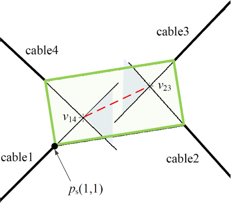
Intersection points of cables
Assume that b1 is expressed as

It is assumed that the intersection points of cables 1/4 and cables 2/3 are denoted as
The algebraic equations of cables 1 and 4 are

Resolving two equations above, the coordinates of
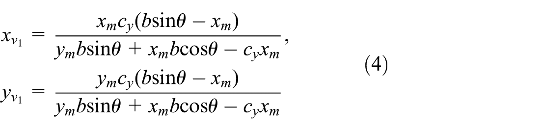
Similarly, the coordinates of

where
Algebraic formulation of WCW with intersection point
The algebraic functions expressing the borders of WCW in terms of coordinates of attachment and intersection points are described as
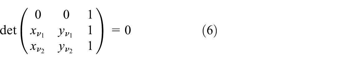

Then, these conditions can be simplified as


Substituting these intersection points into equation (8) leads to

where
Following the same process, the points

Characteristics of workspace boundary of planar robots
From equations (10) and (11), it is observed that both these boundary equations are quadratic curves if matrix
det(
det(
det(
To study the characteristics of WCW for this planar cable-driven robot, the specification of the value of geometrical variables is listed in Table 1.
Specification of the value of geometrical variables (unit: m).

Case 1
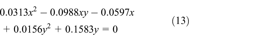
If the orientation angle is adopted as

Accordingly, the corresponding conic curve is displayed in Figure 2, which is part of an ellipse. Together with the other boundary, the potential plane is divided into three areas, as shown in Figure 3. Then, we need to find out which area is the WCW. Thus, one position as

Part of the elliptic boundary of the 3-DOF planar cable mechanism.
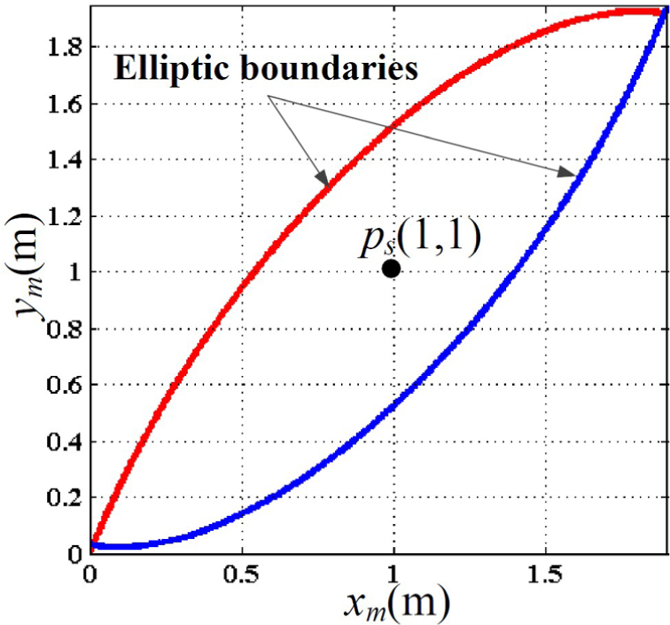
Elliptic boundaries of the 3-DOF planar cable mechanism.

Testing position of potential WCW with elliptic boundaries.
Case 2
If the orientation angle is adopted as θ = π/20 (i.e. det(
Next, the corresponding conic curve is illustrated in Figure 5. Similarly, two hyperbolic boundaries form three areas in the plane as shown in Figure 6. And the testing position
Part of the hyperbolic boundary of the 3-DOF planar cable mechanism.

Hyperbolic boundaries of the 3-DOF planar cable mechanism.
Testing position of potential WCW with hyperbolic boundaries.
Case 3
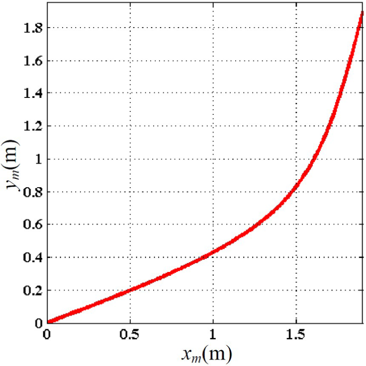
When sin θ = 1/3 (i.e. det(

The above-mentioned boundary together with other part forms the complete border in Figure 8, where the red solid line represents the above formulation and the blue one is the other boundary formulation satisfying equation (11). Additionally, the feasible workspace is constrained in dash box (as shown in Figure 9) formed by two intersection points of two parabolas. However, according to the testing method with

Parabolic boundary of the 3-DOF planar cable mechanism.

The dash box of Figure 8.
To further comprehend the change of the boundary type, the quadratic curves are drawn in the range of

Three types of boundaries of the 3-DOF planar cable mechanism.
Discussion and conclusion
Discussion
This article aimed to obtain the exact boundary of WCW of planar cable-driven parallel robots. The case study focused on a specific four-cable planar robot to obtain the border expression and discuss the corresponding characteristics. However, it may be used in the cases where the number of cables is more than 4. One solution is that first obtaining every set of four-cable combination, calculating each boundary, and finally finding the intersection. Clearly, it will be very complex when the number of cables becomes greater. Thus, the future work is to mitigate this complexity of the problem.
Conclusion
This article determines the boundary expression of planar cable-driven robots and studies the characteristics of the quadratic boundary curves based on antipodal theorem. A feasible determination process is proposed to solve the workspace boundary on a four-cable-driven planar parallel robot. The simulation results show that the types of boundary formulations are conic or straight line (degenerated cases). It also reveals that the border equation of possible WCW is hyperbolic. More importantly, it gives us the information that the upper boundary (Figure 10) with elliptic curve and the lower boundary with hyperbolic curve corresponds to disability of cable 1 while the upper boundary with hyperbolic curve and the lower boundary with elliptic curve corresponds to disability of cable 3. Besides, the workspace boundary equations are the same no matter which intersection points are considered.
Footnotes
Academic Editor: Neal Y Lii
Declaration of conflicting interests
The author(s) declared no potential conflicts of interest with respect to the research, authorship, and/or publication of this article.
Funding
The author(s) disclosed receipt of the following financial support for the research, authorship, and/or publication of this article: This research is sponsored by the National Natural Science Foundation of China (Nos 51275260 and 51475252), the Tsinghua University Initiative Scientific Research Program (No. 2014z22068), and the National Science and Technology Major Project of China (No. 2015ZX040010021).