
Abstract
In this article, a new methodology for type synthesis of uncoupled translational parallel manipulators with 3-degrees of freedom is proposed based on actuation wrench screw theory. Mapping matrix between outputs of the moving platform and the inputs of the actuators for uncoupled translational parallel manipulators is derived. The forms of both the actuated twist screws and the actuation wrench screws of the limbs are determined by means of the condition that the Jacobian is a diagonal matrix with full rank. The steps used to confirm the non-actuated screws of the limbs are also established. Then, procedures for structure synthesis of the limbs are set up and all possible basic structure limbs are enumerated. Some new uncoupled translational parallel manipulators are synthesized by selecting three limbs connecting the platform to the base and two examples are given. The approach proposed is applicable to the type synthesis of uncoupled parallel manipulators with rotational mobility as well.
Keywords
Introduction
Parallel manipulators are typically closed-loop mechanisms composed of a moving platform and a fixed base which are linked by several serial limbs.1–3 Sometimes, in order to obtain certain special characteristics, these serial limbs can be replaced by one or more hybrid chains,4–6 in which there is at least one limb consisting of a closed-loop structure. Compared to traditional serial devices, parallel manipulators have some merits of higher stiffness, larger payload capacity, higher accuracy, and lower inertia. Therefore, parallel manipulators have been applied in many fields, such as virtual machine tools, medical equipments, industrial robots, rehabilitation robots, radar antennas, and sensors. Stewart 7 and Delta 8 are the most famous parallel manipulators applied successfully.
High kinematic coupling is one of the intrinsic characteristics for parallel mechanisms. One independent output motion of the platform is always controlled simultaneously by no less than two actuators or the input of an actuator influences more than two outputs of the platform. Although the coupling contributes high stiffness and large loading capability, it also leads to complicated problems in kinematics, controlling design and path planning, which enhances passive effects for the real applications of the parallel manipulators. Recently, many scholars have focused on research of the reduced parallel manipulators.9–15 This kind of parallel manipulators can be classified into three types in terms of the different forms of Jacobian matrices. The first type is called decoupled parallel manipulator when its Jacobian is a triangular matrix. The second is named uncoupled parallel manipulator (UPM) when its Jacobian is a diagonal one. The third is defined as fully isotropic parallel manipulator as its Jacobian is an identical one. Especially, for the last two types, there exists a one-to-one mapping relationship between the outputs of the platform and the inputs of actuators, which means one output motion of the platform is only controlled by one actuator of the mechanism. So, these manipulators perform well with regard to motion and force transmission capabilities.
Based on the geometrical approach, Kong and Gosselin 16 performed type synthesis of linear translational parallel manipulators, where the Jacobian matrices were diagonal or identical, respectively. Carricato 17 addressed type synthesis of fully isotropic 3T1R parallel manipulators in terms of the screw theory. Gogu18,19 put forward a method for type synthesis of fully isotropic parallel manipulators via linear transformations theory. Furthermore, many new decoupled or uncoupled parallel mechanisms were designed as well. Yu et al. 20 enumerated a kind of orthogonal translational parallel manipulator by Lie group method. Zeng and Huang 21 synthesized some decoupled parallel mechanisms based on screw theory. Zhang and Ting 22 designed a family of uncoupled 2T2R parallel manipulators which were composed of a serial open-single kinematic chain and a hybrid chain.
In this article, a new methodology for type synthesis of the uncoupled translational parallel manipulators (UTPMs) with 3-degrees of freedom (DOFs) is proposed based on actuation wrench screw theory. Basic theory for the method of type synthesis is reviewed briefly in section “Theoretical background.” Mathematic model mapping relationship between the inputs and the outputs of UTPMs is discussed in section “Mapping matrix between the inputs and the outputs of the UTPMs.” Structural synthesis of the kinematic limbs is performed in section “Structural synthesis of the limbs for UTPM,” where the selection principles of the actuated joints driving the platform translation along the given direction are derived as well. In section “Type synthesis of the UTPMs,” type synthesis of UTPMs is dealt with. Finally, some conclusions are drawn in section “Conclusion.”
Theoretical background
Screw
A unit screw is defined by a straight line with an associated pitch, written as 23

where
At the same time, a screw also can be represented by a six-dimensional Plücker coordinate as follows

where the first three components stand of the direction vector
If the pitch is equal to zero, that is,

Otherwise, if the pitch tends to infinite, that is,

A screw multiplied by a scalar
Reciprocal screws
If two screws,

They are said to be reciprocal screws. Here “∘” denotes the reciprocal product.
Physically speaking, if a screw represents an instantaneous twist of a rigid body, its reciprocal screw represents a wrench imposed on the rigid body. When the virtual power developed by the wrench while it moves along the direction of the twist is equal to zero, both of them are reciprocal. Based on equation (5), some conclusions will be obtained as follows: (1) arbitrary two infinite-pitch screws are reciprocal to each other, (2) two zero-pitch screws are reciprocal if their axes are parallel or intersect at a point, and (3) a zero-pitch screw is reciprocal to an infinite-pitch screw if and only if their axes are normal to each other.
Actuation wrench screw
Actuation wrench screw, or called actuation screw, is defined as a screw which is reciprocal to all twist screws within a limb except for the actuated one. Physically speaking, an actuation screw is a wrench exerted on the platform by the actuated twist screw of the limb. In other words, it is a driving wrench imposed on the platform by the actuated joint.
The procedures to solve the actuation wrench screw of the open-single kinematic chain are as follows:
Step 1: to list the twist-system of the kinematic chain;
Step 2: to derive the wrench system,
Step 3: to work out the wrench system,
Step 4: to find the different item between
Thus, it is obvious that the relations of

Mapping matrix between the inputs and the outputs of the UTPMs
The instantaneous output motions of the platform of the parallel manipulator can be described using the twist system of its limbs as follows 24
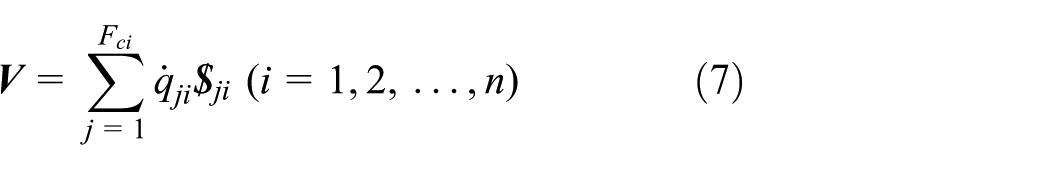
where
Taking the reciprocal product of both sides of equation (7) with the actuation wrench screw,

and
where
Rewriting equation (8) into matrix form yields

where
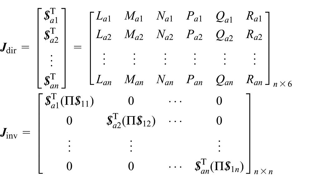
Evidently, the inverse matrix
and
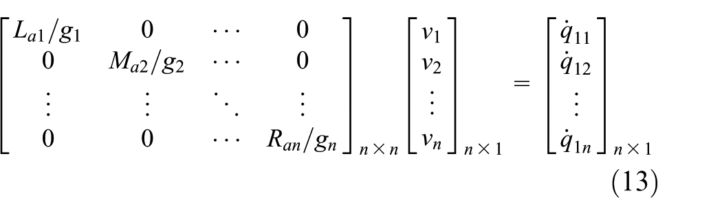
As for n-DOF parallel manipulator, if its output motions of the point on the platform are independent, there are

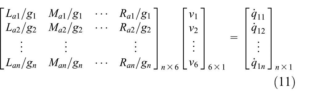
If the UPM is considered, one of the outputs of the platform is only relative to one input of the corresponding actuated joint and irrelevant to other inputs. Then, the inputs and outputs of the mechanism satisfy the function,
According to the definition of the actuation wrench screw mentioned above, we know that it is a driving wrench exerted on the platform by the actuated joint of the limb. When the actuation wrench is a zero-pitch screw (linear force vector), it will push the platform to translate along its direction vector. Similarly, if the actuation wrench is an infinite-pitch screw (pure couple vector), it will force the platform to rotate around the direction of the couple vector. Since any point on the platform of UTPM can only translate linearly in the Cartesian space, the actuation wrench screws imposed on the platform by the actuated joints must be the zero-pitch screws. Then referring to equation (13), kinematics equation of the UTPM is derived as
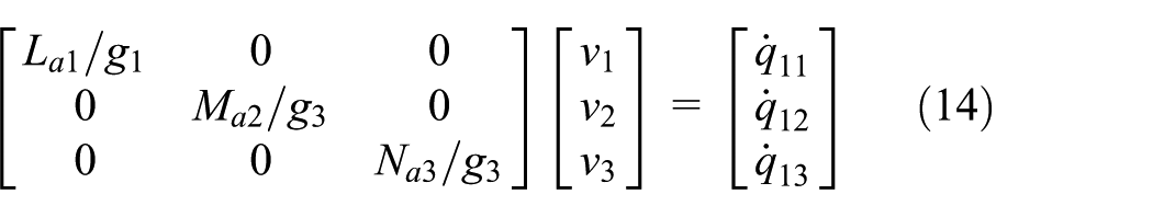
where
Structural synthesis of the limbs for UTPM
Structural synthesis procedure of the kinematic limbs
Structural synthesis of the kinematic limbs is to determine the type, number, and order of the joints within a chain by means of the output-motion characteristics of the mechanism. As far as UTPM is concerned, it is necessary that its one limb only provides independently direct actuation to the platform translation along a specific direction. So, how to set up the synthesis method of the limbs becomes the essentially theoretical basis for type synthesis of the manipulators.
Based on the results in section “Mapping matrix between the inputs and the outputs of the UTPMs,” the general procedures are proposed for structural synthesis of the kinematic limbs of UTPMs as follows:
Step 1: to distribute the controlling target of each limb, such as translation along the given direction. According to the output-motion characteristics of the platform, to determine the actuation wrench screw of each limb based on equation (14);
Step 2: to identify the actuated twist screw of each limb based on the principle that the reciprocal product between the actuation wrench screw and the actuated twist screw is non-zero, that is,
Step 3: to figure out all types of the non-actuated screws of the limbs using the principle that the actuation wrench screw is reciprocal to the all twist screw except for the actuated one. Then discuss the possible number of the different types of screws based on the maximum linear independent groups of the twist screw within a limb;
Step 4: to determine the type, number, and assemble orientation of the actuated and the non-actuated joints in a limb by means of step 3;
Step 5: to enumerate all possible kinematic limbs according to the different connectivity and complete the structural synthesis of the limbs.
The first limb
Without loss of generality, provided that the first limb only supports the driving wrench to the platform translation along the X-axis, referring to equation (14), we get
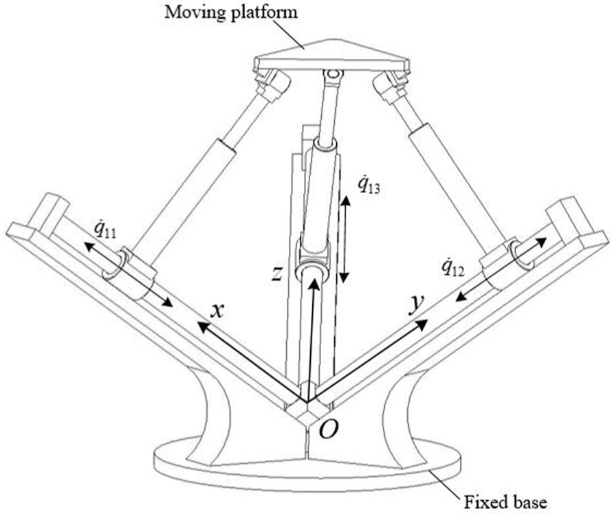
Referring to Figure 1, the coordinate system O-XYZ is attached on the fixed base and o-xyz is mounted on the moving platform. Three axes of the o-xyz are parallel to the corresponding axes of the O-XYZ, respectively.

Actuation wrench screws and their corresponding actuated twist screws within limbs.
Since the first element on the diagonal line of the Jacobian matrix must be non-zero, see equation (14), the actuation wrench screw,

Evidently,
Furthermore, the first element on the diagonal line should also satisfy the following condition

where
Type 1: indefinite-pitch screw
In this case, the actuated twist screw of the first limb can be defined as

Obviously, the value of

Substituting equation (18) into equation (17), we have
Type 2: zero-pitch screw
In this case, the form of the actuated twist screw of the first limb can be written as

Equation (19) shows that the value of

where

Substituting equation (21) into equation (20), we get
In terms of processes above, the possible forms of the actuated twist screws of the first limb are obtained: one is an infinite-pitch screw parallel to X-axis and other is a zero-pitch screw parallel to Y-axis. Then, based on the rule that the actuation wrench screw is reciprocal to all the twists except for the actuated screw, the non-actuated twist screws of the first limb will be determined.
Case I—when the actuated twist screw is an infinite-pitch screw parallel to X-axis, the possible forms of the non-actuated twist screws can be
I-1—zero-pitch screw parallel to X-axis. This kind of screw forms a set connected directly to the platform. Its number is at least two and no more than three.
I-2—infinite-pitch screws perpendicular to X-axis. This kind of screws can be placed at any positions in the limb and its number is no more than two.
I-3—zero-pitch screw intersected with the axis of
Case II—when the actuated twist screw is a zero-pitch screw parallel to Y-axis, the possible forms of the non-actuated twist screws can be
II-1—zero-pitch screw parallel to X-axis. This kind of screw forms a set connected directly to the platform. The number is at least two and no more than three. However, any zero-pitch screw cannot be inserted in this set.
II-2—zero-pitch screw parallel to Y-axis. Its axis is intersected with the axis of
II-3—zero-pitch screw (or called idle screw) perpendicular to Y-axis. This kind of screw intersects with the axis of
II-4—infinite-pitch screw perpendicular to X-axis. This kind of screw cannot be placed between two zero-pitch screws parallel to Y-axis. The number is no more than two.
After determining the actuated twist screw
In order to simplify the assembly forms, provided that the axes of the two adjacent joints are parallel or perpendicular to each other in the limbs. The basic kinematic limbs are enumerated by means of the rules proposed (see the fourth column of Table 1). The limbs including the complex joints are listed in the fifth column. The subscripts u, v, and w represent the translational direction of the prismatic pairs or the rotational axis direction of the revolute joints, respectively. The symbols with the same subscript denote their axes are parallel, otherwise, perpendicular to each other. The subscript m denotes the axis of the corresponding prismatic pair which is normal to the axes of both adjacent joints. The superscripts t and r represent to select the translational or rotational displacement of the actuated cylindrical joint as the input of that limb. The symbol underlined indicates that there is a rotational idle DOF associated with the joint.
Type and structure of the kinematic limbs for UTPMs.

If let
The second limb
This limb supports the driving wrench to the platform translating along Y-axis. According to the condition that the second element on the diagonal line of the Jacobian matrix is non-zero, see equation (14), the actuation wrench screw

From equation (22), we know that
Similarly, the second element on the diagonal line also satisfies the following condition

where
By using the similar procedures in section “The first limb,” the possible forms of the actuated twist screw

or

which implies that the actuated twist screw of the second limb may be an infinite-pitch screw parallel to Y-axis or a zero-pitch screw parallel to Z-axis. That is to say, the actuated joint can be selected as a prismatic pair with axis parallel to Y-direction or a revolute joint with axis parallel to Z-direction.
As the forms of both the actuation wrench screw
Case I—when
I-1—zero-pitch screw parallel to Y-axis. This kind of screw forms a set connected directly to the platform. Its number is at least two and no more than three.
I-2—infinite-pitch screw normal to Y-axis. This kind of screw can be placed at any positions in the limb and its number is no more than two.
I-3—zero-pitch screw intersected with the axis of
Case II—when
II-1—zero-pitch screw parallel to Y-axis. This kind of screw forms a set connected directly to the platform. The number is at least two and no more than three. Any zero-pitch screw cannot be inserted in this set.
II-2—zero-pitch screw parallel to Z-axis. Its axis is intersected with the axis of
II-3—zero-pitch screw (or called idle screw) perpendicular to Y-axis and intersecting with the axis of
II-4—infinite-pitch screw perpendicular to Y-direction. This kind of screw cannot be placed between two zero-pitch screws parallel to Y-axis. Its number is no more than two.
After the actuated twist screw and the non-actuated screws are determined, all possible structures of the second limb can be enumerated based on the differences of the connectivity.
If let
The third limb
This limb provides the direct actuation to the platform along Z-axis. Similar to the process in section “The first limb” and section “The second limb,” the forms of both the actuation wrench screw

and


Obviously,
Then, the forms of the non-actuated screws of the third limb are obtained as well.
Case I—when
I-1–zero-pitch screw parallel to Z-axis. This kind of screw forms a set connected directly to the platform. The number is at least two and no more than three.
I-2–infinite-pitch screw normal to Z-axis. This kind of screw can be placed any positions in the limb and its number is no more than two.
I-3–zero-pitch screw (idle screw) intersected with the axis of
Case II–when
II-1–zero-pitch screw parallel to Z-axis. This kind of screw forms a set connected directly to the platform. The number is at least two and no more than three. Any zero-pitch screw cannot be inserted in these twist screws.
II-2–zero-pitch screw parallel to X-axis and intersected with the axis of
II-3–screws of zero-pitch (idle screw) intersected with the axis of
II-4–infinite-pitch screw perpendicular to Z-axis. This kind of screw cannot be intersected between two zero-pitch screws parallel to X-axis. The number is no more than two.
When the actuated twist screw and the non-actuated screws are determined, all possible structures of the third limb can be enumerated based on the different connectivity.
If let
Type synthesis of the UTPMs
Type synthesis
An UTPM can be generated by connecting the platform to the base by use of three limbs shown in Table 1. Each one of the limbs gives direct actuation to one DOF of the platform. However, the total connectivity of three limbs should be considered carefully when to construct the mechanisms. For non-overconstrained parallel mechanism, the total connectivity of its limbs must hold the following condition 25
where
For the non-overconstrained translational parallel manipulator,
For example, a novel non-overconstrained UTPM is obtained by assembling three R v U vu P m R u -type (revolute-, universal-, prismatic- and revolute-joint) kinematic chains, shown in Figure 2. The axes of three actuated revolute joints amounted on the base are perpendicular to each other. Similarly, thee revolute joints attached on the platform should also meet the same assembly condition. Then, the first limb, R y U yx P m R x , controls the motion along X-direction of the platform. The second and the third limbs control Y- and Z-direction motions, respectively. The velocity equation of the manipulator can be derived as

where f is the length of the lower arm of every limb, measuring the distance between the first two revolute joints, and

3-RUPR non-overconstrained UTPM.
Since the Jacobian of the manipulator is a diagonal matrix, there exists a one-to-one mapping relationship between the output velocity vector of the platform and the input velocity vector of the actuated joints.
Another new manipulator is shown in Figure 3, which consists of three C
t
u
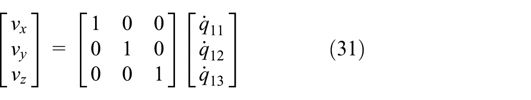
Referring to equation (31), it is more interesting that all components on the diagonal line of the Jacobian are constantly equal to 1. Therefore, the condition number of the Jacobian is equal to 1 throughout its whole workspace as well. In other words, it is a fully isotropic translational parallel mechanism, which performs well with regard to force and motion transmission capabilities.
3-C
Mobility analysis of the 3-RUPR parallel manipulator
The screw theory is a valid mathematic tool to analyze the mobility of parallel manipulator and it is used to deal with the following contents. Referring to Figure 2, the kinematic screw (or called twist) of each joint in the first limb in the fixed frame, O-xyz, can be described as

where
Then, using the reciprocal product principle, the constraint screw (or called wrench) of the first limb can be derived as follows

Obviously, the wrench
Similarly, the constraint screw system of the second and the third limbs can also be obtained, and we have

Both of them,
In terms of equations (33) and (34), we know that three constraint screws of limbs limit together three-rotational DOFs of the mechanism. Therefore, the platform can only translate along three axes of the Cartesian coordinate system. In addition, it is obvious that three constraint screws are independent linearly, so there is no redundant screw among them, which implies that this mechanism is non-overconstrained.
Conclusion
In this article, a new methodology for type synthesis of the UTPMs is proposed based on the actuation wrench screw theory. Selection principles of the actuated joints driving the platform to translate along the given direction are explored by means of the different types of the actuation wrench screws, zero-pitch, or infinite-pitch screws. The process for structure synthesis of limbs is established and many new limbs with idle joints are also enumerated. Two 3-DOF UTPMs are taken as examples to verify the correctness and feasibility of the type synthesis method presented. It is worth noting that the mechanisms have fully isotropic performances when the actuated joints are prismatic or cylindrical pairs. In addition, the method proposed here is also applicable to the type synthesis of lower mobility UPMs with the exception of 3-DOF spherical type.
Footnotes
Handling Editor: Hiroshi Noguchi
Declaration of conflicting interests
The author(s) declared no potential conflicts of interest with respect to the research, authorship, and/or publication of this article.
Funding
The author(s) disclosed receipt of the following financial support for the research, authorship, and/or publication of this article: This study was supported by the National Natural Science Foundation of China (50905055), Program for Innovative Research Team of Henan University of Science and Technology (2015XTD012), Fundamental Project of Key Scientific Research of Henan Advanced Education (18A460001), and Program for Postgraduate Innovative Foundation of Henan University of Science and Technology (CXJJ-2016-ZR03).