
Abstract
Automation is critically important for sustainability in meat production, where heavy reliance on human labour is a growing challenge. In this work, a novel robotic Meat Factory Cell (MFC) platform presents the opportunity for unconventional automation in pork meat processing, particularly abattoirs. Instead of following line-based approaches, which are the main option today, it uses robotics and Artificial Intelligence (AI) to perform complex cutting and manipulation operations on entire unchilled pork carcasses, with awareness of biological variation and deformation. The long-term goal of the MFC is to take a pork carcass as an input and produce seven primal outputs: hams, shoulders, saddle, belly and entire organ set. However, the MFC platform is under continuous development – therefore, this paper aims to demonstrate it through a specific use-case: shoulder removal. The system is evaluated based on data from testing and development sessions (June–November 2022), with a total of 34 attempted shoulder removals. Data regarding the MFCs’ ability to handle variation, in addition to success rate and process timing models are presented. Qualitative feedback from skilled butchers is also discussed. The authors propose that, as well as technical development of the platform, it is important to consider new ways of comparing unconventional systems with their conventional counterparts. Innovative manufacturing systems have more to offer than raw speed and volume; traits such as flexibility, robustness and scalability – particularly economic scalability – should play a prominent role. Future legislation and standards must also encourage innovation rather than hinder innovative robotics solutions.
Keywords
1. Introduction
The integration of automated systems and technologies is crucial for ensuring the long-term viability and sustainability of the red meat industry. Without the use of automation, the sector may struggle to meet the increasing demands for efficiency, productivity and environmental responsibility that are necessary to remain competitive in the future. Therefore, it is essential for stakeholders in the red meat sector to embrace automation as a means of achieving sustainable practices and maintaining their relevance in a rapidly evolving global marketplace.
This article is predominantly focussing on applications for pork meat production, which has grown substantially in the past 50 years. The Food and Agriculture Organization (FAO) reports that between 1960 and 2010, global pork meat production more than quadrupled in response to increasing demand for animal-based protein (Food and Agriculture Organisation, 2013). It is the most produced terrestrial meat product in the world, with ca. 40% of production in China, 21% in the EU-27 and 11% in the USA (European Commission, 2023a). With world population expected to grow from 8 billion in 2023 to almost 10 billion by 2050 (United Nations, 2017), and in the absence of equally efficient (Ahmad et al., 2022) or accepted (Varela et al., 2022) plant-based alternatives, demand for meat products will continue.
Automation is considered as a key enabler to increase productivity, decreasing labour dependency and improving both manufacturing time and cost (Hassoun et al., 2023). This is particularly important in a sector which must increase productivity to meet global demand, while facing labour shortages (Amin et al., 2023; Coluccia et al., 2021; Milbourne and Coulson, 2021) and typically having small profit margins. While empirical data is not publicly available for competition reasons, noted also by Zira et al. (Zira et al., 2021), it is clearly important for processors when considering the economic feasibility of automation. Thinking historically, many fondly recall Henry Ford’s first production lines in 1913, being inspired by his visit to meat factories; he took the disassembly process of slaughter lines and reversed it (Van Driessche, 2017). At the time, meat processing was leading the way when it came to optimising the arrangement of workers and tasks to maximise productivity. Fast forward to the modern day however, and this perspective no longer holds – where many manufacturing sectors, automotive included, have made extensive use of robotics and automation equipment to increase productivity, the red meat sector has fallen behind. This is confirmed with a visit to almost any red meat processing plant: one may find robotic systems at end of line stations, handling some aspects of packaging and palletising, but when advancing upstream it is almost certain that large sections of equipment will be operated by teams of workers performing repetitive tasks at an impressively high speed.
1.1. Motivation and objective
The motivation for this work is to present the technical development of a new platform for meat processing, the so-called ‘Meat Factory Cell’ (MFC), which dares to move away from line-based processing strategies. Instead, it is designed such that a combination of robotic cells can be arranged in parallel (see Figure 1), with each cell broadly performing the tasks of conventional primal cutting and tri-sectioning. Notably, those two operations take place in different parts of a meat processing plant, or even in an entirely different facility, with carcasses typically being chilled before tri-sectioning. Comparison between conventional processing (left), and that proposed in the Meat Factory Cell (right), assuming the starting point of a clean entire carcass (i.e. after stunning and killing) and the end point of packing and palletising in both cases. The early stages of conventional meat processing are executed as series of linear disassembly steps, where typically there is little opportunity for parallel activities within the line. The Meat Factory Cell platform on the other hand, allows a series of similar cells to take raw input and produce primal parts on a logistic unit, or rack, ready for inspection. Those parts may be chilled if desired but may also be sent directly for cutting and deboning. From this point, the envisaged process is like conventional meat processing. Image: Alex Mason, NMBU.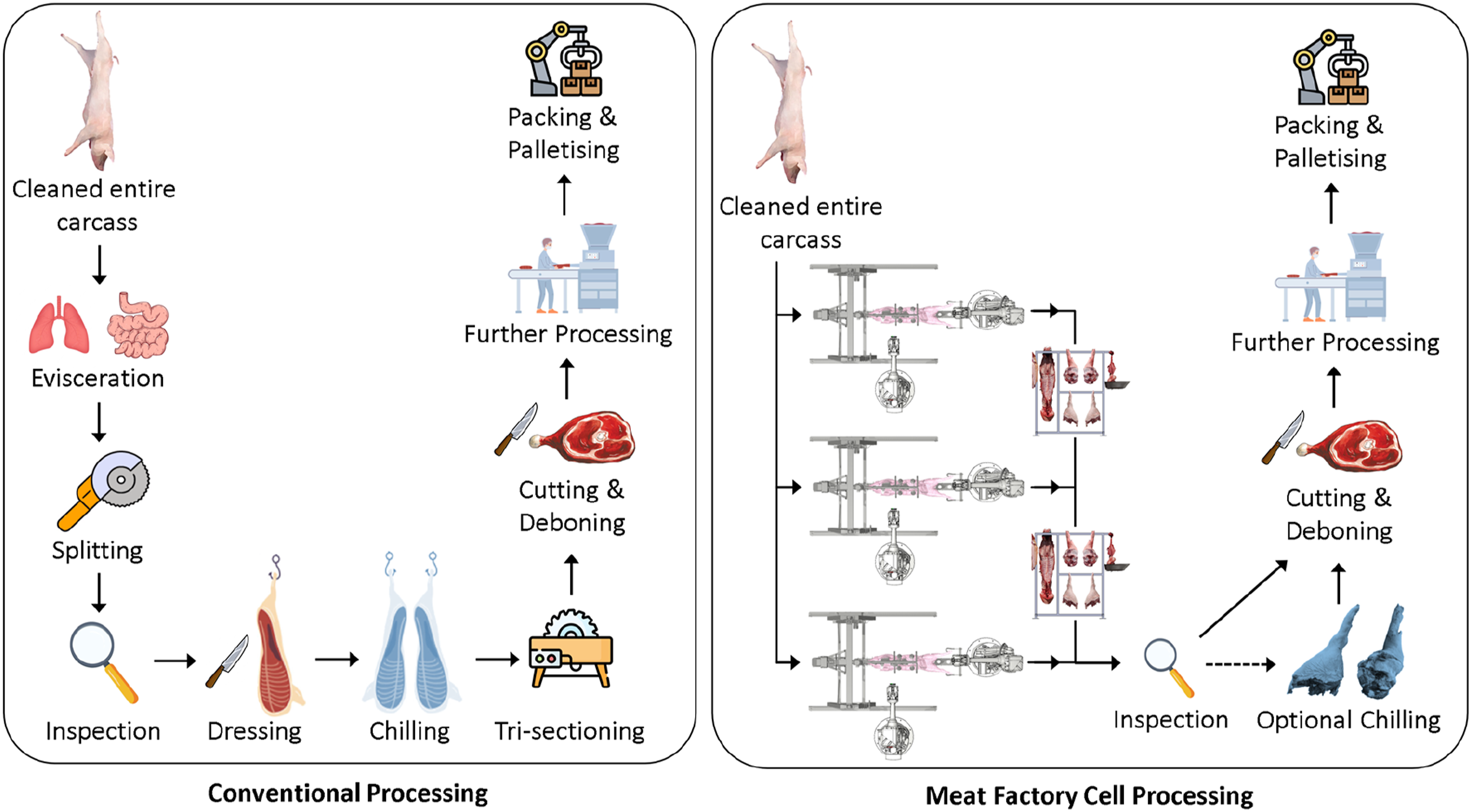
This novel platform can offer flexibility, for example, to accommodate input volume variation. This is relevant where factors affecting consistency of supply may occur, for example, due to seasonal variations (e.g. extreme hot or cold weather conditions which stress the animals) limiting transportation or due to disease outbreaks (e.g. African Swine Fever) which can abruptly halt distribution. Robustness is also a potential benefit, through fault tolerance and opportunities for simultaneous planned maintenance, alongside production. In today’s line-based production, stoppages cause major disruption for upstream and downstream processes. Most importantly however, the MFC offers the means for smaller enterprises to access automation with a predictable financial scalability; the cost of a cell can be predictable, and the number of cells can be equated with productivity. The rough concept for the MFC process was first presented by Alvseike et al. (Alvseike et al., 2018), and later a proof of concept cutting method to support this process was reported (Alvseike et al., 2020). The present article reports, for the first time, on the physical realisation of the MFC platform. It draws from the original concept and implements the aforementioned cutting methodology. A notable difference between the system implemented and the original concept from Alvseike et al. (Alvseike et al., 2018), however, is that while they proposed a semi-automatic implementation using butchers to perform cutting operations, the realised system is designed to be fully automatic.
The MFC, as is the case for many research platforms, is under continuous development to improve its functionality and speed. Therefore, the objective of this article is to report on one specific task: shoulder removal from an entire carcass. The system, further described in Section 2, combines several robots, 3D computer vision, tooling and artificial intelligence (AI) to produce a platform which is aware (or cognisant) of, and responsive to, the natural biological variation and deformation during cutting operations performed on pork carcasses. Notably, the carcasses are unchilled and pre-rigour mortis, therefore implying a greater degree of deformation than with a chilled carcass.
1.2. Brief state-of-the-art
As noted earlier, meat processing plants heavily rely on manual labour. Naturally, there are exceptions, and several recent and collectively comprehensive reviews of the state-of-art (De Medeiros Esper et al., 2021; Kim et al., 2023; Romanov et al., 2022; Xu et al., 2023) illustrate this. These recent publications preclude the need for an extensive state-of-the-art review in this article, but nevertheless, a concise background is relevant to help understand the need for the developed MFC.
Technologies available on the market today largely represent incremental developments of robots and machines that complement or replace traditionally automated stations, still using line-based processing. As noted in (Kim et al., 2023), there are commercial solutions for specific tasks within the conventional processes; for example, in the abattoir there are systems for cutting the abdomen and brisket, for carcass splitting, and for handling head or jowl separation. Collecting the machines that exist today together to form a production line does increase automation levels, but doing so requires a considerable initial investment. This means that the big players in the market have been able to automate to a much greater extent than those considered small- and medium-scale: the important message being that production volume is a decisive factor. In the pork meat sector, where the authors have been most intensively focussed, processing volumes of 600–700 carcasses/hour are considered necessary before extensive automation is economically viable. In Europe, most processors fall well beneath that threshold; in Norway, the most productive lines rarely achieve even half this volume. According to (Khodabandehloo, 2022), a return-on-investment period in the region of 18–24 months is required before users are motivated to invest in commercial systems.
This situation indicates that a different way of thinking is required. It naturally opens the potential for philosophical debate: society could consume less (Cheah et al., 2020), more resources could be applied to meat alternatives (He et al., 2020) or meat production could become highly centralised (Almena et al., 2019). The authors, however, have been more considerate of how it might be possible to make automation more accessible, using flexible and scalable cognitive robotic systems.
The development of single- or multi-robot systems to perform more complex tasks has gained moment in recent years. Notable examples have been a lamb-deboning room from Scott (Seaton, 2022) and several deboning robots from Mayekawa (Mayekawa, 2017); HAMDAS-RX for ham deboning and WANDA-RX for shoulder deboning. These systems, which are commercially available in some form, mimic parts of the current conventional processes and automate them. Other systems, which remain presently in the research domain, include models of two or three arm robot cells (Long et al., 2013a, 2013b; Nabil et al., 2015) for small, non-specific, meat cutting tasks. A prototype dual-arm system, plus holder, for deboning of hams which made use of an X-ray sensor to accurately locate bone structures has also been reported (Delgado et al., 2013). The Danish Technological Institute (DTI) has recently demonstrated a robot cell (Hinrichsen et al., 2022) which is analogous to tri-sectioning equipment, the process by which a chilled half carcass is portioned into fore-, hind- and mid-sections. While conventional equipment includes saw blades and therefore cuts in straight lines, the DTI system enables a curved cut; two 3D cameras enable prediction of a pathway, and a small robot with customised pneumatic knife-tool performs the removal. This has the potential to improve yield but is still in development. Work on assistive robotic implementations, for example, Exoscarne, have also been reported (Maithani et al., 2021). Besides those recent advancements noted, development of systems which adapt to biological variability and handle deformable objects, like food, has been limited. Among the reasons for this have been the computational costs associated processing (and simulating) 3D objects when compared with planar objects (Sanchez et al., 2018).
The MFC system reported in this paper is the first of its kind to be implemented for pork meat production, and specifically targets activities in the abattoir, where entire carcasses are processed into their primal parts. Therefore, the scope is different from the systems of Mayekawa and DTI, for example, which are focussed on deboning of hams and shoulders, or tri-sectioning. The MFC also goes much further than other reported work (Long et al., 2013a), which was largely model based. The lamb-deboning room demonstrated by Scott, while impressive, is not aimed at small- and medium-processors. The process implemented is still based on a linear production line, which achieves high volume – machines and robots perform the repetitive tasks that today, in most parts of the world, are still performed by humans. It is also notable that the MFC system relies entirely on 3D imaging of the carcass exterior for prediction of cutting pathways. It also performs the entire slaughter process within a relatively small footprint, and in a way that can be also implemented by human operators. Systems such as those from Scott have made use of dual-band X-ray, which has a higher implementation cost than an off-shelf 3D camera solution. For small- and medium-volume processors, it is these types of costs which reduce the economic attractiveness of automation, a factor the authors seek to address.
2. Materials and methods
The MFC platform, illustrated in Figure 2, implements a unique process for primal cutting of pig carcasses. The MFC consists of several key hardware and software components, which are summarised in Section 2.1. Not all components are demonstrated within the scope of shoulder removal, but nevertheless an overview of all components is included to give the reader a complete picture of the platform. The process implemented by the MFC is briefly noted in Section 2.2, with a more detailed overview of shoulder removal provided, since this is the article specific use-case. The method of evaluating the system in regard of shoulder removal is described in Section 2.3. The MFC platform, developed and assembled at the Norwegian University of Life Sciences, Norway. Each of the robots is labelled within the image, with the ABB IRB4600 robots also including information on their specific configuration in brackets (payload, kg/reach, m). Image source: Alex Mason, NMBU.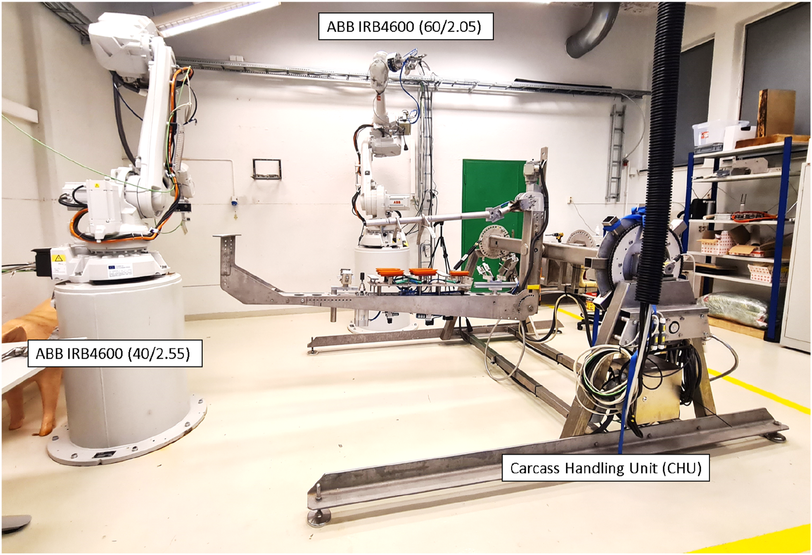
2.1. Robots
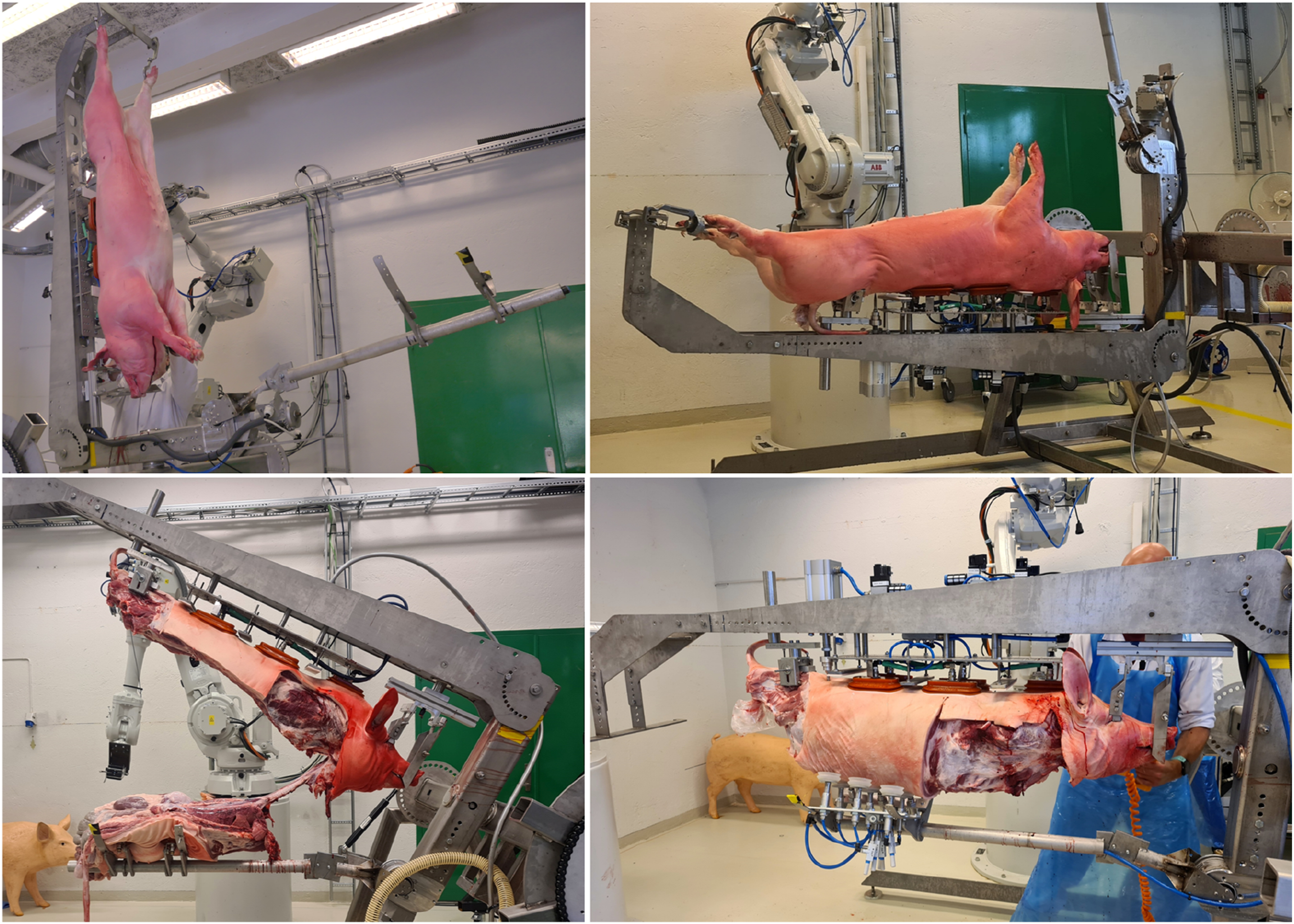
The MFC consists of three robots. Two general purpose industrial robots are used to perform cutting, gripping and imaging tasks related to the carcass. Those robots are supplied by ABB and are IRB 4600 variants in 60/2.05 and 40/2.55 configurations (maximum payload in kg/maximum reach in m). Each robot is equipped with a manual tool changer from the Schunk SHS series (Schunk, 2020) to enable rapid tool exchange with minimal reconfiguration – end of arm tooling is further described in Section 2.1.3. The third robot is a bespoke Carcass Handling Unit (CHU). The system was first developed and tested based on manual operations (Sødring et al., 2022), prior to being automated to give 3 degrees of freedom (DOF). Those DOF (or axes), also illustrated in Figure 3, are as follows: 1) A 90° rotation to enable collection of carcasses in a vertical orientation when hung and transported via overhead rails, and presentation thereafter in a horizontal orientation for processing in the MFC (Figure 3, top left compared with top right). 2) A 180° rotation while the carcass is horizontal so that the carcass may be presented with its back facing down- or upwards – this can also be utilised for smaller rotation angles (e.g. 5–10°) to enable access or muscle stretch during cutting operations (Figure 3, top right compared with bottom right). 3) A rotation (ca. 60°) in the smaller of the two supporting bars (Figure 3, bottom left), which when used in combination with the first DOF enables opening of the carcass. The carcass handling unit, CHU, showing the 3-DOF available for presentation of a carcass for imaging, removal and gripping actions. Carcass in vertical (top left) and horizontal positions (top right), with transition to the back of the carcass facing upward (bottom right) and opening of the carcass to expose the gastrointestinal tract (bottom left). Image source: Alex Mason, NMBU.
Other notable features of the CHU include a vacuum gripping system to secure the carcass at the neck and along the back, as well as two mechanical grippers which secure the head and another (after ham removal) fixating the pelvic bone. The floor space required for the MFC, as shown in Figure 2, is ca. 18.4 m2 (5.1 m × 3.6 m).
2.1.1. Imaging and artificial intelligence
Imaging is performed by a 3D depth sensing camera (FramOS D415e, UK) mounted as an end-of-arm tool on the IRB4600 in 40/2.55 configuration. The tool, which combines a camera and a knife is illustrated in Figure 4 (left). The knife element is described further in Secion 2.1.2. The camera is moved through six predefined locations: two on the left side of the CHU, two on the right side and two above. Imaging at all six locations enables almost complete 3D reconstruction of a carcass (de Medeiros Esper, et al., 2022a). The camera position in each location is such that no specific method or tool is required to estimate carcass length, and this parameter is not used for generating cutting paths. An open dataset containing stepwise cutting data collected during the MFC development is available (de Medeiros Esper, et al., 2022b). The shoulder removal in the MFC uses either one or three camera positions, depending on the stage of the cutting process. Both 2D images and depth data are captured to enable prediction cutting pathways and gripping points for the IRB4600 robots to execute. The end of arm tool, combining a 3D camera and knife (left) and a custom labelling tool (right), based on CVAT. In this labelling tool, lines are drawn by expert butchers to label (in this example) surface cuts for the shoulder, and also ribs. Coloured circles represent feature labels which were also gathered and used to guide an AI approach to limb gripping. Image source: Dmytro Romanov, NMBU, and Anton Popov, Ciklum.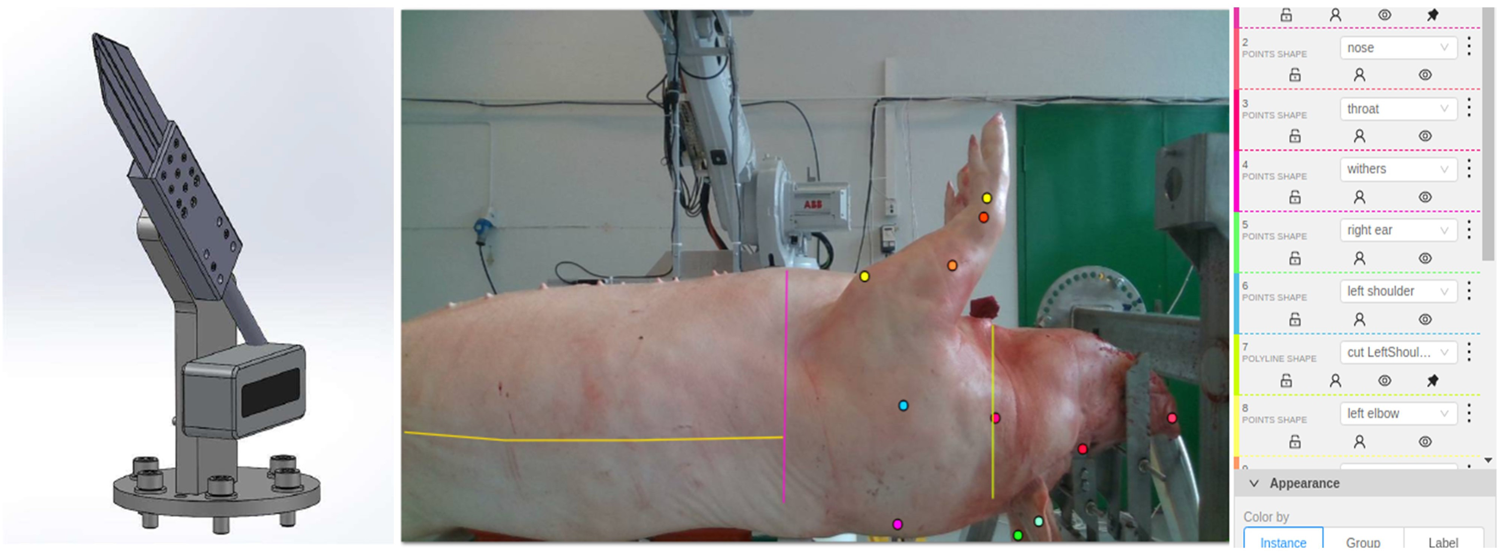
Training of the AI, in the context of this use-case, has been performed using the captured 2D images. It is noted that, like other parts of the platform, the AI is an interchangeable component, which maybe improved or replaced. Expert butchers from Norway have labelled 2D images (from 94 individual carcasses, processed manually or semi-manually within the CHU) in a stepwise fashion. This training set contains labelled data from entire carcasses in the range 82.5–165.0 kg and with lengths 177–201 cm. Labelling was performed in a bespoke tool created using the Computer Vision Annotation Tool (CVAT, https://www.cvat.ai/) by several experienced butchers from Animalia AS (Norway) and Danish Technological Institute (Denmark) – an example of the CVAT interface is illustrated in Figure 4 (right).
This enabled the training of an AI-model which can predict cutting pathways based on the current state of the carcass cutting process. A U-Net like architecture (Ronneberger et al., 2015) with a ResNet-34 backbone is used for predicting a 2D mask with a cutting pathway as an output. The predicted mask can be projected directly to 3D space (i.e. as a point cloud), but the cut paths are unordered. As a result, post-processing is required to generate a polyline which represents a set ordered points that describe the generated cutting pathway. Those must then be transferred from 2D to 3D space and merged where necessary. Next, the 2D points are mapped, or projected, onto the 3D depth map of the carcass, and shifted from the visible surface to a point inside the carcass. This is necessary since the specific predicted points should correspond to actual points that will be followed by a knife tip in the working area, and the knife tip should be below the cutting surface viewed by camera. Finally, approach and exit points are added to the path to satisfy physical constraints imposed to avoid collisions between the two IRB4600 robots during harmonised operation. The post-processing algorithm for polyline generation, presented in a pseudo-form, is as follows:
1) Perform mask skeletonisation (see Figure 5, left).
2) Calculate approximating straight lines using Iterative Hough Transform (Dalitz et al., 2017).
3) For each line: a) Determine the points of the mask lying in the vicinity of the line; b) Cluster the obtained points near to the straight line; c) Filter out the clusters formed only at the intersection points of the line with another line; d) Project filtered clusters onto a line; e) Determine the segment end-points; f) Project the segment end-points back onto the mask (see Figure 5, middle); g) Determine segment end-point pairs and sort by distance (least to greatest).
4) For each segment end-point pair: a) If a segment containing the end-point pair is already paired with another segment, skip; b) If an end-point is outside of the original image boundary, skip; c) If the segments are parallel and the distance between the end-point pairs exceeds a threshold α, skip; d) If a segment containing the end-point pair has not been paired with another segment: i) If the segments are not parallel, calculate their intersection point; ii) Else, calculate the midpoint between the end-points and ensure it is less than the threshold α; e) Generate a polyline line from the obtained points (i.e. intersection or midpoint).
5) If a cutting path should be generated based on the combined image data from two camera positions, then: a) Calculate the distance between different polylines (end-point and project distance); b) Select pairs with minimal distance; c) Merge polylines based on segment averaging.
6) Shift points from outer (imaged) surface to inside the carcass (see Figure 5, right).
7) Insert/append predefined path approach and exit points.
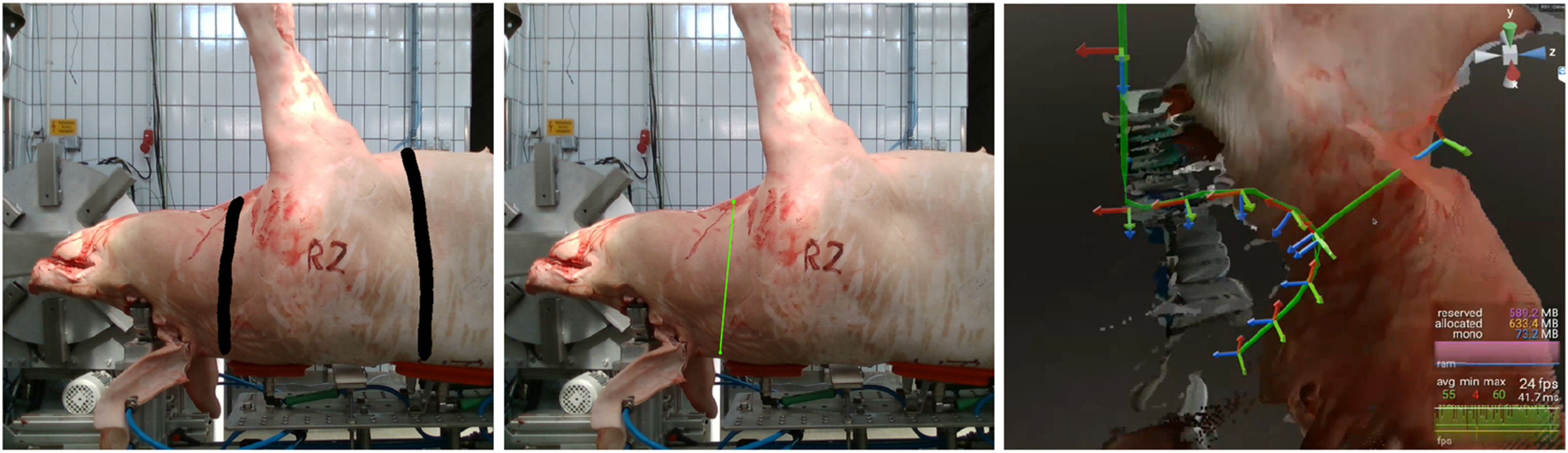
An illustration of the main steps from one or more 2D images to a predicted cutting path, projected in 3D space. First, a mask is overlaid onto a 2D image (left), after which a line is generated to represent the cutting path (middle). Placement of the cutting path is dependent on progress through a defined workflow – further description is provided in Section 2.2.3. While the mask, shown in black, defines a general area where a cut should take place, the much narrower green line within the mask boundary represents a significantly refined prediction. Finally, the path is projected into the 3D space, which is coordinated via Ocellus (right). Image source: Alex Mason, NMBU, and Oleh Smolkin, Ciklum.
The process for gripping the limbs when attached to a carcass is conceptually similar; however that process produces just a single point, rather than complex path. The cutting pathway may be visualised prior to execution, using the bespoke software Ocellus (Bytemotion AB, Sweden) – Figure 5, right. From a motion planning perspective, often both feasible and optimal motion planning strategies are discussed (Mukadam et al., 2018). Ocellus allows an operator to visually ensure a path is feasible before execution and correct it if not. This is possible either through display of the path to a screen or monitor, or through richer experience in a Virtual Reality (VR) environment (see also section 2.1.4). In addition, Ocellus maintains the global coordinate system, ensuring that the depth information collected from the camera unit, the pathways generated by the AI, and the eventual movements of robots are synchronised with respect to the working area around the carcass. The global coordinate system is maintained in relation to the tool centre point (TCP) of the robot equipped with the camera. This is based on an investigation (de Medeiros Esper et al., 2022c) which evaluated several methods of coordinate system calibration (within the MFC environment), including a charuco cube, a double-sided charuco board and the robot TCP.
2.1.2. End of arm tooling
Several ends of arm tools, in addition to the camera described in Section 2.1.1, are implemented in the MFC. The tools are shown in Figure 6, and briefly described as follows: 1) A smart knife (Mason et al., 2022), mounted in combination with the imaging camera to the IRB4600 robot in 40/2.55 configuration. The knife is used for removal of limbs, as well as being intended for cuts related to separation of the gastrointestinal tract. This tool includes sensorisation, enabling real-time feedback regarding knife contact and cutting depth. 2) A saw, mounted on the IRB4600 in 40/2.55 configuration. The saw, an EFA SK 30/18 (EFA, Germany), is used to make a cut along both sides of the carcass, separating the carcass belly from the back. The saw implemented in the MFC at present is an off-the-shelf handsaw, modified for robotic (or manual) use. 3) A bespoke pneumatic gripper, designed for use with the large primal cuts and modelled to withstand ca. 20 kg payloads with deflection less than 0.2 mm (Christensen, 2021); this is in line with repetitive handling of pork limbs (both fore and hind). The authors have successfully used the gripper to lift larger parts of a carcass (e.g. the saddle) weighing in excess of 50 kg. 4) A bespoke electrical gripper, designed primarily for gripping, pulling and lifting the gastrointestinal tract (Takacs et al., 2021). Unlike the gripper noted in 3), this device includes sensors to control the force applied when gripping, as well as a slip detection sensor to enable change of grasp if the target object is not secure. End of arm tooling in the MFC: smart-knife (top left); saw (top right); pneumatic gripper for large primal cuts (bottom right); and electrically driven gripper for organ handling (bottom left). Image source: Alex Mason and Luis Eduardo Cordova-Lopez, NMBU, and Tamas Haidegger, Obuda University.
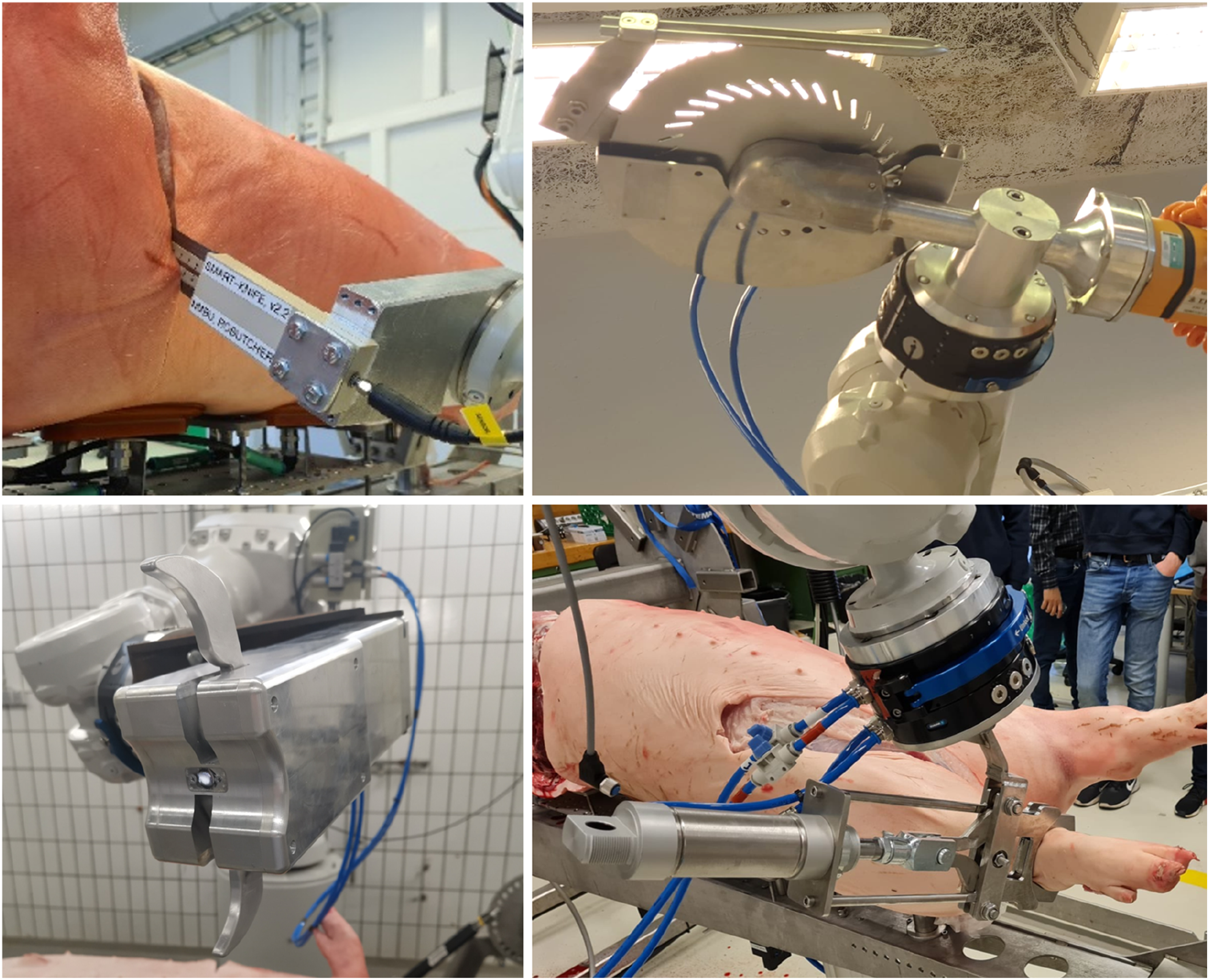
Tools (2) and (4) are not required to perform the shoulder removal use-case.
2.1.3. User interface
The MFC system has several interfaces enabled, as the authors have explored both conventional and unconventional methods for user interaction. Those interfaces include the following: 1) Direct robot interaction via hard-wired buttons or teach pendants. In the current implementation of the MFC, these are used predominantly as a safety tool, whereby an operator has the possibility to stop the cell activity in the case of unexpected or unsafe robot movement, or manually move the relevant robot out of some undesirable position. 2) Interaction via a web user interface, where specific actions can be executed based on button clicks, even remotely. Further, information regarding the status of the MFC subcomponents, such as process or component state, can be displayed to the user. 3) A Stream Deck MK.2 (Elgato, Germany) interface, implementing a series of interactive buttons (16 in total) where functionality can be adjusted depending on the process state. This, to a large extent, mirrors the web interface described in 2), but without a specific requirement for a screen and mouse/keyboard input. 4) A Virtual Reality (VR) interface, which enables an experienced user to visual predicted pathways, redraw those pathways were deemed necessary (e.g. if prediction failed or was inadequate), and execute cutting tasks. The specific hardware used is Vive Pro (HTC, Taiwan), which can be used in both wired and wireless configurations.
For the purposes of the use-case in this paper, only the interfaces described in (1) and (2) are used.
2.1.4. Global integration and control
Integration of the MFC hardware and software components is enabled via Node-RED (https://nodered.org/). This development tool, originally developed for Internet of Things (IoT) applications, has received growing interest as a general platform for automation. In the MFC, it allows all hardware and software components to be defined as nodes, and for those nodes to be wired together in a series of workflows. Those workflows form the control logic that enable the MFC platform to execute a series of tasks to achieve some overall objective. In this paper, the focus is on shoulder removal (described in Section 2.2.3), but it can equally be applied to all other removals (noted in Section 2.2.2). Node-RED is also the basis for the web user interface noted in Section 2.1.4. An overview of how the system is connected, in terms of signalling and data flow, is provided in Figure 7. An overview of the MFC system subcomponents and their interconnects for signalling (dotted red lines, on/off functions) and data flow (solid red lines). Image: Alex Mason, NMBU.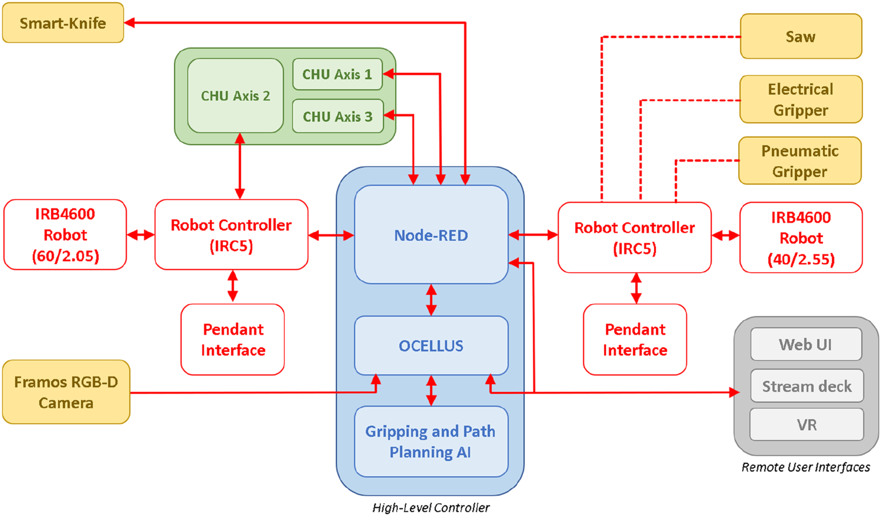
In complex systems, multiple control systems are often employed, arranged in a hierarchical structure (see Figure 8). At the top of this hierarchy is the high-level controller (see also Figure 7), which oversees logic and system integration. Its outputs serve as inputs for the lower-level controllers. In the MFC context, the high-level controller is responsible for generating cutting paths, gripping points and defining the rotation angles for one of more of the CHU axes. With cutting paths and gripping, specific coordinates are then relayed to the robot’s controller (IRC5), which has a low-level controller tasked with manoeuvring the robot to the specified coordinates. Angles are sent to a programmable logic controller (PLC) to position the CHU as desired. An overview of hierarchical control for the MFC in this use-case. Image: Ian Esper, NMBU.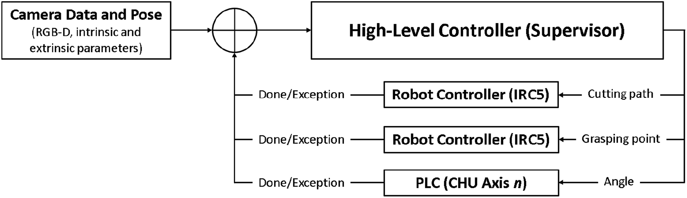
Inputs for the high-level controller in this configuration include images, depth information, and both intrinsic and extrinsic parameters. These inputs are the elements to generate a point cloud, which serve as the surface for calculating cutting paths.
The feedback for the high-level control, as implemented for this use-case, is based on errors generated by the IRC5 controller. Once the error has been raised, a new set of data must be captured and processed to update the proposed cutting pathway based on the current state of the carcass. This step is necessary since part of the previous cutting attempt could have been executed, changing the surface to be cut.
2.1.5. Logistic unit
The final component of the MFC is the logistic unit, or ‘rack’ (see Figure 9). The purpose of this bespoke equipment is to provide a means for both presentation and transportation of the MFC outputs. The rack has been designed such that the MFC outputs can be loaded directly via robot interaction. Passive hooks and grippers are implemented for this purpose. Presentation is important from the perspective of food safety; in conventional pork meat processing, trained veterinarians visually inspect carcasses immediately after splitting. Since the process (see Section 2.2) applied in the MFC differs from conventional processing, the rack represents the closest possible equivalent to today’s practise. Further, the rack presents a means to transport and distribute the MFC outputs to different parts of a meat factory, potentially offering a greater level of carcass and primal traceability (MADEC et al., 2001) than is possible today. While increased resolution of traceability is something that the industry would welcome, it is not further discussed in this paper, as to date, it has not been a central focus for the authors. A prototype logistic unit, or rack, produced to hold the outputs of the MFC; those being hams, shoulders, the entire back with head, the entire belly and the complete organ set. The image on the left shows examples of all relevant parts affixed to the rack, while the centre and right images show fixation of the organ set and limbs, respectively. Images: Luis Eduardo Cordova-Lopez, NMBU.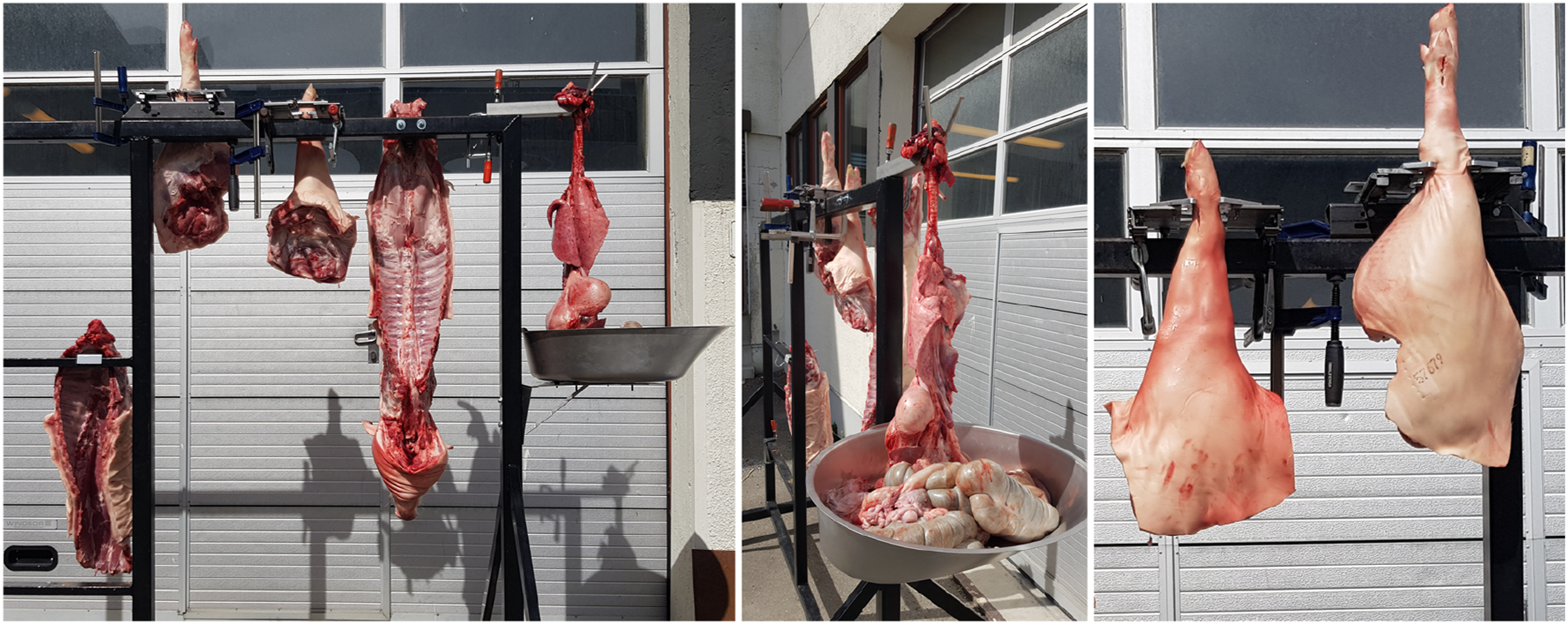
2.2. Carcass processing in the MFC
2.2.1. Carcasses
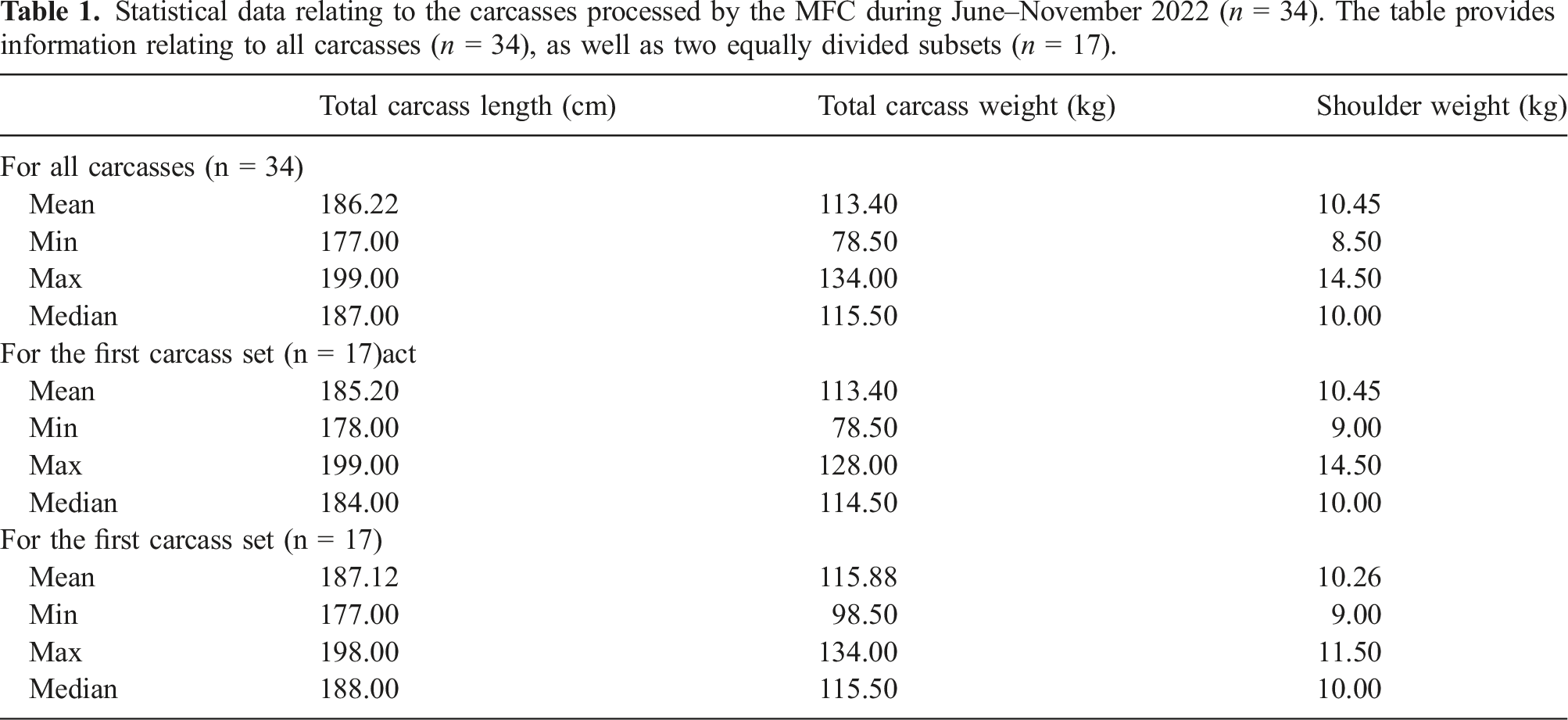
Statistical data relating to the carcasses processed by the MFC during June–November 2022 (n = 34). The table provides information relating to all carcasses (n = 34), as well as two equally divided subsets (n = 17).
2.2.2. Overview of the MFC process
The MFC implements an unconventional procedure for primal cutting of pork. The procedure is based on the principle of working from the outside of the carcass inward, thus leaving the gastrointestinal tract in place for much of the process. In conventional slaughter, the gastrointestinal tract is typically removed first. This new process has been previously documented in detail (Alvseike et al., 2020), thus this section provides only a brief overview, and then focuses in greater detail on the process of shoulder removal.
The cutting process in the MFC follows these main steps: 1) Collect the carcass from overhead rails, and position it horizontally and securely, ready for cutting. 2) Remove limbs, starting with the forelimbs and then the hams. This requires synchronised cutting and gripping actions, using both IRB4600 robots. 3) Rotate the carcass through 180°, such that the back of the carcass is facing upwards. 4) Perform incisions on both sides of the carcass with a saw, following a line from near the pelvis, to the neck, thus separating the belly from the back (or saddle) of the carcass. 5) Open the carcass, cutting any remaining connective tissue between gastrointestinal tract and saddle in the process. 6) Grip and remove the gastrointestinal tract. 7) Remove saddle and belly from the CHU. 8) Wash down the CHU and tooling ready for next carcass.
The output of the cell should be loaded to a logistic unit (see Section 2.1.6) automatically. The primal parts are as follows: two shoulders, two hams, saddle (including head and tail), complete ribs and belly and complete gastrointestinal tract.
2.2.3. Shoulder removal
The shoulder removal process can be expressed in the form of a workflow (i.e. a series of logical steps), as illustrated in Figure 10. This workflow is implemented in Node-Red (see Section 2.1.5). Cutting is separated into two main types of cuts: outer cuts, which pierce the skin, and inner cuts which separate the shoulder muscle(s) from the carcass. There are exactly three outer cuts, whereas the number of inner cuts is not predefined. Overview of the shoulder removal process, which is implemented in the MFCs’ Node-RED workflow. Image: Alex Mason, NMBU.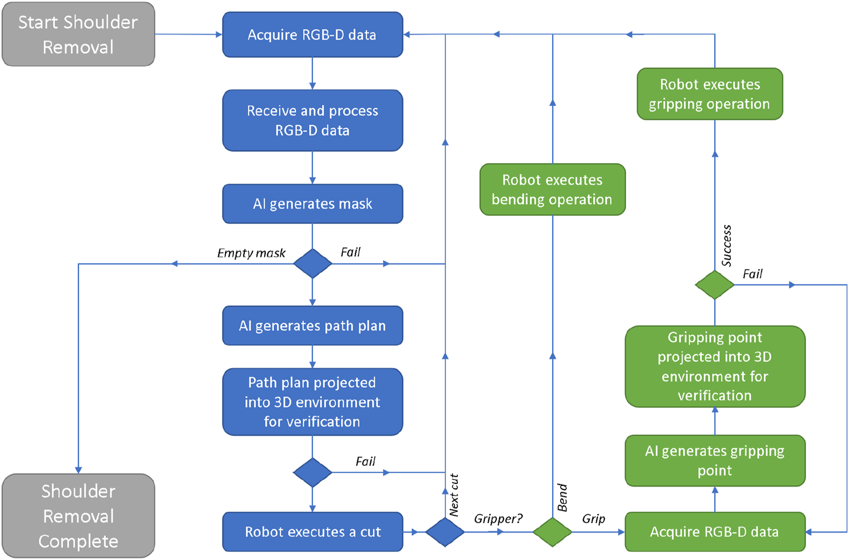
In more detail, the process starts with imaging in three positions, with the goal being to obtain a side and top view of the target shoulder. A further image of the opposite shoulder (the one not being cut) is also used to determine the width of the carcass in the section where the cut is being made. This is necessary in case the carcass is partially occluded by its limbs when viewed from the top, and allows us to determine where the middle of the carcass is, and to what point it is necessary to cut. As a result, the overall stability of the AI-model is improved. After imaging and successful cutting path prediction, a cut on the neck side of the shoulder is performed. A second three-position imaging cycle is undertaken, this time so that a cut on the rib side of the shoulder can be performed. Next, a side image is acquired, from which the position of the limb can be obtained for gripping. After gripping, the limb is bent away from the carcass slightly to give better sight (and access) of the chest area. The bending also stretches the muscle tissue, making it easier to cut. From here, single images are required only from the top view. The first chest cut pierces the skin, nominally joining the end-points of the first two cuts along the chest. From here, a cycle of bending, imaging and cutting is followed until the removal is completed. Feedback on completion of the shoulder removal process is signalled when the AI system returns an empty mask (see Section 2.1.2) during pre-processing.
As noted in Section 2.1.5, during the cutting action, it is possible for either robot to signal an error (e.g. joint out of range, excessive detected force). This signal is a source of feedback, via Node-Red, and enables the system to recover from these errors. In this use-case, the recovery strategy when such an event occurred was to stop cutting and move on to attempt the next cut. This is often successful, as the partial cut operation, plus additional manipulation of the limb, provide a new view for AI to generate a cutting pathway. The topic of feedback is discussed further in Section 4.
2.3. Evaluation methodology
The MFC is an innovative platform designed to demonstrate the potential of new techniques in AI, robotics and tooling in the context of red meat cutting. The eventual goal of the authors is to implement the complete cutting process, automatically, with the platform. To date, the most well-developed operation has been shoulder removal; it was a natural starting point for the development tasks and has therefore been the cutting operation which has received the most attention of the authors. The results presented in this article are based on data collected during the period June–November 2022, when the MFC underwent an intensive period of testing and incremental development at laboratories in the Norwegian University of Life Sciences (Ås, Norway). A combination of quantitative and qualitative data was collected using a standardised template for each carcass. Video footage was also recorded and archived for later annotation.
The information collected was as follows: weight of each primal cut, total carcass weight, carcass length, detailed accounts of the procedure applied, and constructive feedback from expert butchers present for each attempt. Later, the qualitative information relating to each carcass was analysed to provide quantitative data relating to overall success rate of shoulder removal, in addition to quantification of the point(s) in the procedure (as detailed in Section 2.2.2) where failure occurred most often. It was also possible to determine the total number of cuts required for each removal. Using this information, in addition the archive video footage, it is possible to calculate total process time, as well as estimates of process time if the cell was running at a higher speed. Comparative removal times from two expert human butchers performing the removal in a similar way are also included in Section 3.3 for comparison purposes. This data is based on video annotation from 31 slaughters that took place in the Autumn 2019, when an early prototype of the CHU was being tested at an abattoir in Tønsberg (Nortura SA, Norway).
3. Results
3.1. Weights and length
Statistical information related to the weight and length of each carcass is provided in Table 1. The information is provided for all carcasses (n = 34), as well as for two equally divided groups (where n = 17 in each group). This is due to consideration of system performance as development progressed, as described further in Section 3.2. The total carcass weight is calculated as the sum of all dissected parts, as per the process description in Section 2.2.1, several hours post stunning and bleeding. It is therefore expected that 5–10 kg of fluids is lost prior to weighing. The typical live slaughter weight for finisher pigs in Norway is ca. 120 kg (Bonesmo and Enger, 2021), indicating that the carcasses processed can be considered standard. Carcass length is taken as the distance measured from the tip of the ham to the tip of the snout; such information is not typically gathered in conventional slaughter.
The MFC, specifically the CHU, does allow for manual adjustment to accommodate variation in carcass length; however, no changes were required to accommodate the carcasses received and document in Table 1.
3.2. Stepwise shoulder removal
An example of a stepwise shoulder removal is illustrated in Figure 11. The process begins with an uncut carcass, which has three outer cuts applied to pierce the skin around the shoulder. Before the final outer cut, the shoulder is gripped to ensure a good camera view of the chest area, and to avoid collision between the knife and limb. Once all outer cuts are complete, a cycle of inner cuts and limb bends are performed, as described in Section 2.2.3. Stepwise shoulder removal using the MFC platform. The steps are ordered row by row, left to right. In brief, the steps show: (a) the entire carcass before cutting; (b) neck outer cut; (c) rib outer cut; (d) gripping; (e) chest outer cut; (f) bending #1; (g) inner cut #1; (h) bending #2 and inner cut #2. (i) bending #3; (j) inner cut #3; (k) inner cut #4; (l) bending #4; (m) inner cut #5; (n) inner cut #6; (o) inner cut #7, with removal completed; (p) shoulder removal complete. Note that the number of inner cuts and associated bends can vary from carcass to carcass, and as noted in Section 3.3, has been reduced as a result of developmental work. Image source: Alex Mason and Michaela Pinceková, NMBU.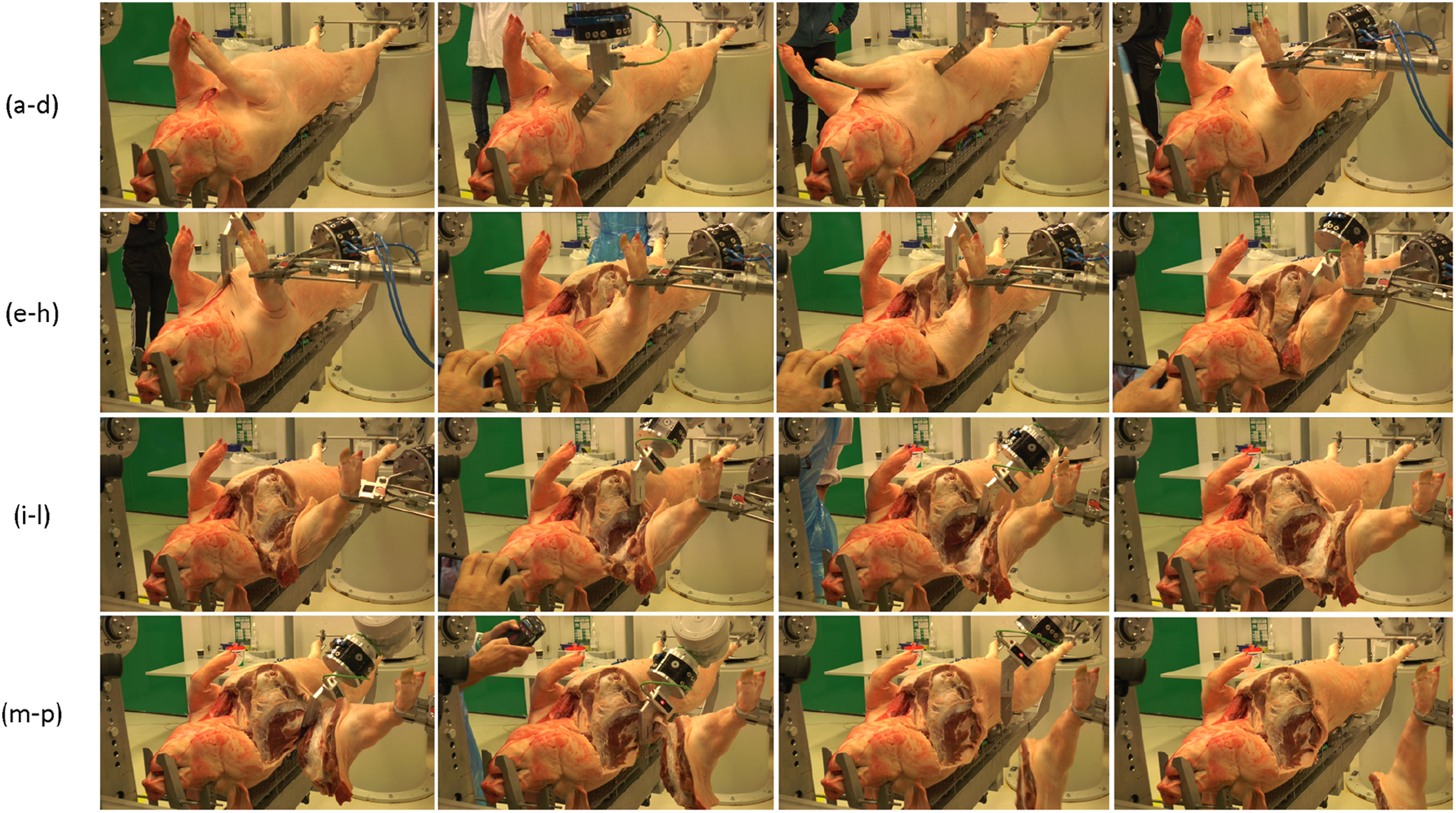
From the 34 attempts to perform removal, a total of 13 completely autonomous removals where performed (success rate, SR, of 38.2%). In this study, the results are also segmented in two, by time, to consider improvement of the system success rate. Improvements were expected due to continuous critical evaluation and development of the MFC. Thus, the first and final 17 attempts are also considered separately. In regard of complete removal, only three autonomous removals were possible (SR = 17.6%) in the first 17 attempts. Of those 17 attempts, 12 attempts either did not attempt inner cuts, or attempted insufficient inner cuts to perform a completed removal. In the latter 17 attempts, the number of successful removals increased to 10 (SR = 58.8%). This is expected given the development and improvement of the system throughout the data collection period. Regarding gripping, which is also autonomous, only one failure was noted in all 34 attempts (SR = 97.1%). Failure typically occurs due to awkward positioning of the limb, close to the chest rather than extended.
When performing outer cuts, the neck, rib and chest cuts had similar success rates (67.6%, 67.6% and 70.6%, respectively). Cuts can fail for a variety of reasons, but the most common noted are failure of the robot to reach some position within the predicted path (e.g. joint out of range errors), or that the cut is either too deep, too shallow, or too short (i.e. incomplete). In the first 17 attempts, the success rate for neck, rib and chest were 52.9%, 64.7% and 58.8%, respectively, while in the latter 17 attempts this improved to 82.4%, 70.6% and 82.4%. Improvements with the neck and chest cut are noted to be greater, mainly due to robot joint configuration adjustments; this enabled the robot to reach the neck and the points on the chest cutting path furthest away from the robot (with reference to Figure 2, ABB IRB4600 40/2.55). This is rarely a challenge for the rib outer cut as it is closer to the respective robot.
The number of inner cuts, unlike outer cuts, varies by carcass. It has also varied during the data collection period. In total, 24 shoulder removal attempts had the potential to perform a complete removal. Of those 24, the mean number of inner cuts per removal was 10.1; for the first 12, the average as 12.8; and for the second 12, it was reduced to 7.7. The maximum number of inner cuts performed in a single removal was 23, and the minimum 5. The reason for the higher average number of inner cuts during the beginning of the trials was related to the shoulder blade, which is not visible beneath layers of muscle or connective tissue. Adjustments to the AI path planning, to incorporate better the curvature of the carcass rib cage, assisted in reducing shoulder blade collisions, and therefore the number of required passes. This is relevant since the number of cuts required has a direct impact on the overall process time for removal.
3.3. Process time
Data collected during the manual removal of 31 carcasses showed that the mean shoulder removal time was 36s, with a minimum of 20s and maximum of 60s. Cutting was performed by two different butchers, depending on availability.
Process time for shoulder removal in the MFC presented in this article has been estimated by recording the time for individual operations (via annotation of video footage) performed during the removal, and also having knowledge of parameters such as the pre-programmed robot movement speed during those operations. The process can be broken down as follows: the imaging time for inner and outer cuts (ITinner or ITouter); the time taken for the tool to approach inner or outer cuts (ATinner or ATouter); the cutting time for inner or outer cuts (CTinner or CTouter); the time taken for the tool to exit outer cuts (ETinner or ETouter); the time required to grip the limb (GT) and; the time required to perform a single bend operation (BT). The time required for the AI to perform predictions can also be accounted for, both for gripping (AITgrip) and cutting (AITcut). In addition, it is necessary to know the number of outer cuts (NCouter) and the number of inner cuts (NCinner). This enables calculation of imaging time (ITtotal), cutting time (CTtotal), gripping time (GTtotal) and AI time (AITtotal), as per equations (1)–(4). The total process time (PT) can be calculated as the sum of these values, as indicated in equation (5).
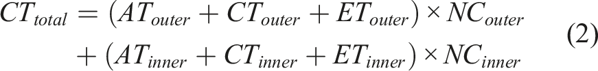


Values for those defined parameters are presented in Table 2; several different process time models are estimated, which are based on the following criteria: • • • • Process parameters and calculations based on several models; model one represents the parameters used in the MFC during testing, with the remainder assuming increased robot speed or optimisation of imaging and AI execution.


The limited robot movement speeds indicated in model 1, and used in the MFC today, are imposed for safety reasons during evaluation due to close observation of workers around the platform. The increased robot speeds in models 2–4 are set based on discussion with experienced robot integrators (Robot Norge AS, Norway).
It is assumed that care must be taken during cutting, due to the risk of impact of the knife blade with hard objects, particularly bone. Single operation imaging (rather than iterative), as in model 4, is based on parallel work (unpublished) by the authors at the Norwegian University Life Sciences, using alternative methods for imaging and AI. This method, using similar hardware, takes a little longer to create a set of cutting predictions but only requires a single execution per removal. The estimated process times for models 1–4 are (in s) 955, 383, 297 and 204, or (in min), 15.9, 6.4, 5.0 and 3.4, respectively. The topic of process time is further discussed in Section 4.
3.4. Qualitative feedback
Feedback from butchers during the experimental period was typically focussed on aspects related to the quality of the cutting performed by the robot, in comparison to how they themselves might have performed the task. Specifically, discussion centred around the length and depth of the cut, as well as its position.
During the first 17 attempts at removal, feedback was mostly centred on performance of the MFC in relation to outer cuts. Specifically, the cuts tended not to be deep enough (by several cm) or long enough, often by > 5 cm. On several occasions, the attempts made by the robots had to be finished by the butcher to enable the system to proceed on and attempt the next process step.
During the latter 17 attempts at removal, the feedback centred more on inner cuts. However, where outer cuts are documented, the position and length are noted to be more in line with expectation. In the few cases where adjustments are suggested, those refer to length or depth of cut and were in the range of ca. 1–2 cm. The feedback regarding inner cuts tended to describe refinement of cutting depth, optimisation of tool orientation and improvements of the predictive model to maintain consistent cutting depths. Those issues were largely address during the development period. However, by far the most recurrent feedback has been collision of the cutting tool with the shoulder blade – this was noted also in Section 3.2 in regard of the required number of inner cuts. While this improved through the period, it was difficult to eliminate entirely. An example is illustrated in Figure 12. Example of collision between the shoulder blade and knife in the MFC. Both an instance of the collision (left) and the result (right) are shown; typically, the knife scores the shoulder blade and if the resistance is sufficient a stop condition is triggered by the robot controller. Image source: Alex Mason, NMBU.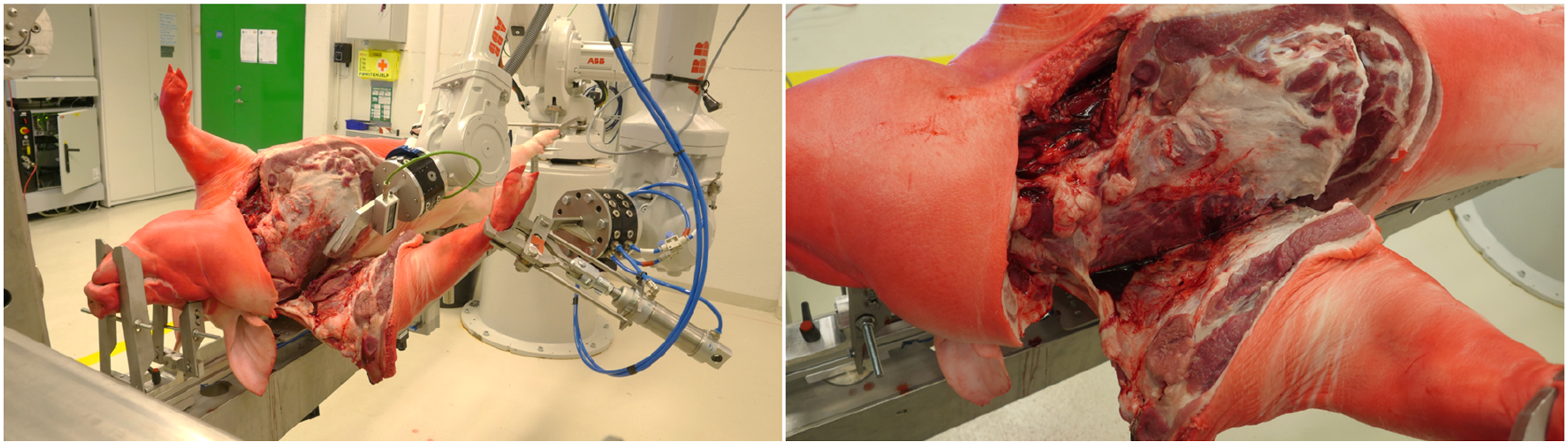
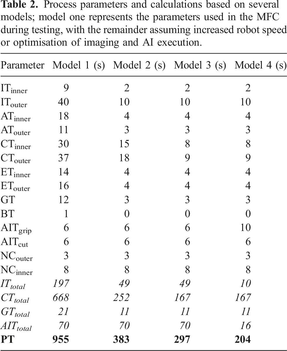
Butchers in some cases also provided feedback regarding the quality of the removal. They noted, in particular, that the robot cutting tended to leave more neck muscle on the shoulder than would be typical in conventional production. An example, for comparison purposes, is illustrated in Figure 13. This is a shortcoming of the AI approach implemented, whereby the training set consists of 2D images labelled by experts. Labelling takes place on the 2D plane, that is, on the visible surface, whereas the actual cutting takes place at some point beneath that surface, that is, where the tip of the knife is located. This is further compounded by curvature of the carcass toward the last parts of the shoulder removal process. As a result, the achieved cuts are not in full compliance with the Norwegian standard, but the topic is further discussed in Section 4. Due to the continual development during the period, it was impossible to assess quantitatively the effect of this on, for example, yield, or to gauge the consistency of the robots in this regard. Example of shoulder removals performed by human (left) and robot (right). Image source, Alex Mason, NMBU.
4. Discussion
The MFC, in respect of shoulder removal, is shown to be capable of handling standard finisher pork carcasses coming from Norwegian abattoirs. For the carcasses processed in the study period, no special considerations of carcass weight or length have been necessary. In part, that is due to the effective standardisation in breeding and rearing of pigs for slaughter. As noted earlier, the training set collected for the purposes of this use-case contains labelled data from entire carcasses in the range 82.5–165.0 kg and with lengths 177–201 cm. That is not to say that the MFC would be able to handle extreme cases; pigs reared specifically for speciality dishes (e.g. so-called ‘barbeque pigs’, which are significantly smaller than typical slaughter weight animals), or sows, which can have weights exceeding 200 kg, would not be accommodated in the system as it is today. The main limiting factor for the MFC in this regard (as presented) is the CHU, specifically its automatic mechanical adaptability to a broader range of carcass lengths. Those cases noted however represent a very small minority of overall slaughters, and abattoirs are accustomed to having facilities, often separate from the main processing lines, for performing special or emergency slaughter. This limitation, therefore, is not considered unique to the MFC.
Regarding the removal process described in Section 2.2.3, this was put in place while system software and hardware subcomponents were still under development. The process is therefore designed to guarantee function above all else. It is considered that the process could be improved in a number of ways, including adjustment of the position and number of images taken; increase the number of parallel activities, rather than purely linear process execution; reducing the number of cuts and/or bends required to perform removal; further optimisation of cutting tool and angle; adjusting robot layout (or type) to address issues with robot reach; incorporation of automatic recovery of the system if a cutting error occurs (e.g. collision); and modification of the CHU to improve carcass presentation and security. Several of those noted are already under active consideration by the authors, and the list is not exhaustive. For example, the CHU is under continuous development to improve options for carcass presentation, which can reduce likelihood of occlusion when imaging and collision when cutting. In addition, an alternative approach to cutting pathway prediction, using a digital twin derived from computer tomography reference data combined with real-time depth imaging, was recently implemented (De Medeiros Esper et al., 2024). The approach is expected to reduce process time (as shown in Table 2, model 4), but perhaps more importantly, it increases awareness of the skeletal structure, allowing future cutting pathways to better avoid the shoulder blade, and other bone structures. This will be even more relevant in removal of the ham, for example, where it is expected that the robot navigates separation of a ball joint connecting the femur to the hip. No such joint exists in the shoulder. Furthermore, this new approach is expected to improve yield when compared to the AI implementation reported here, as expert labelling can be performed in a 3D environment and therefore better accommodate the expected depth and position of a knife.
Development of new capabilities for the MFC is a topic of future work. At the time of writing, the system has also been demonstrated to perform ham removal (see Figure 14), although that work is still at an early stage. The MFC platform also offers opportunities to improve knowledge in relation to organ handling, an area that is noted by Kim et al. (Kim et al., 2023) to lack current solutions. Specifically, it has already developed a process for carcass opening, and methods for securely gripping the trachea (see Figure 14). Examples of further MFC capabilities, including ham removal (left) and organ handling (right). These operations are currently under development and optimisation. Image source: Alex Mason, NMBU.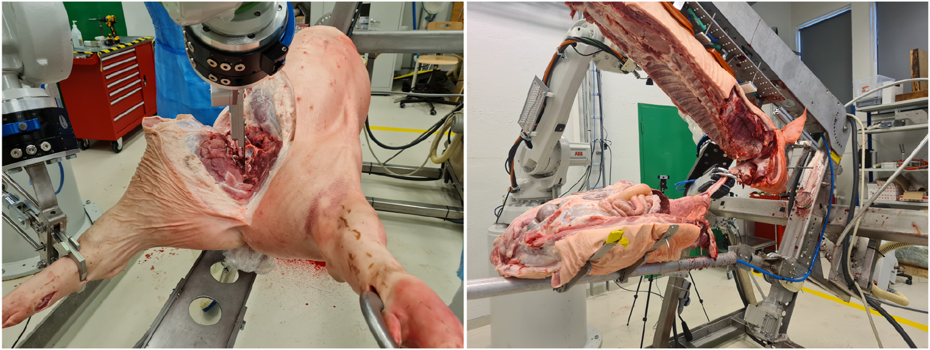
It is acknowledged that the current system speed and yield for shoulder removal are not yet competitive with conventional industrial solutions. Discussing yield first, it was noted by butchers observing the MFC that the system tended to leave more neck muscle on the shoulder than they are accustomed to. Certainly, this is an area for further improvement, and further trials of the MFC during 2023 aim to better quantify characteristics relating quality, hygiene and yield for example. Seaton (Seaton, 2022) also noted challenges with yield in the Scott lamb-deboning room, writing that four robots for hind quarter deboning were removed from a production line as their presence encouraged workers to improve their own performance to a level that the robots could not compete. For the MFC, continued development of AI-models and methodology will likely be the main factor contributing to future improvement, although the authors believe that this should be tackled jointly in the context of customisation. Conventional AI-models, using 2D data, require many hours of data labelling, a process which must be repeated should the cutting requirements change. Across Europe, the cutting standards for pork shoulders and hams vary significantly, and therefore approaches which improve the speed and flexibility of customisation will be greatly desirable. The approach taken in parallel by the authors, and noted earlier, uses a pig digital twin, where a 3D model contains information related to desired cuts. Changes to the 3D model, for example, by meat processors with varying requirements, directly impact the operations performed robotically. While the work of the authors is at an early stage, such approaches have been successfully implemented for more rigid materials, including those in the construction (Lee et al., 2022) and automotive sectors (Schuh et al., 2021). The speed of execution, currently ca. 10 s for a complete shoulder removal, may be further increased by hardware acceleration techniques (Isachsen et al., 2021), for example.
System feedback is a further area for investigation. In this use-case, as little feedback as possible is incorporated during cutting actions. In the early stages of development, consideration was given to force-feedback, a popular strategy in robotics (Long et al., 2014), and perhaps a method most similar to how human butchers experience cutting. Nevertheless, there are also some drawbacks: for example, the forces involved in cutting muscle tissue with a well-maintained blade are rather small, compared with the forces when a large robot impacts a solid object such as a bone. Furthermore, once the bone has been struck, it is often too late; it causes blade dulling and damage, the knife may become embedded within the bone, and in some cases the bone may splinter. Finding suitable devices, that is, with sufficient sensing range, frequency and robustness, was challenging, and cost was also a factor. As a result, the authors chose a different direction. For example, as noted in Section 2.1.3, a ‘smart-knife’ was developed to provide feedback on knife contact and depth, and a bespoke electrical gripper which is able to change applied gripping force based on an optical flow slip detection method. The implemented Node-Red workflow approach means that these tools, and others (including those based on force), can readily be integrated into the MFC platform to provide process feedback and improve the system performance.
Moving to process time, where a human butcher can perform the specified removal, on average, in 36 s, the MFC requires 955 s (15.9 min). It is noted that the robots in the MFC today run slowly, and that is a conscious choice by the authors, to consider safety of the operators within the experimental environment and to enable closer inspection. There are also sub-optimal operations; for example, the knife is raised to a height of ca. 4m after each cut to allow hazard free inspection. It is theoretically demonstrated that increasing operating speed of the robots, during cutting and non-cutting operations will significantly reduce process time, as will optimising the cutting path prediction methodology (noted previously). Another distinct possibility is performance of parallel operations to reduce process time; this could (with sufficient equipment) include removal of both shoulders simultaneously. More work is required in this area however to better understand the possibilities, and therefore generate realistic, rather than optimistic, models.
It is very important to consider that there is no single operation in today’s conventional processing lines which directly replicates the removal performed in the MFC. This makes it challenging to directly compare process time. The closest analogy is a shoulder a being prepared for dry-curing (e.g. Spanish Paleta). Then, the shoulder conventionally undergoes a combination of processes; this includes tri-sectioning of a dressed half carcass, and then manual cutting and trimming of the shoulder by a butcher. The process time in this case can be considered as the sum of both stated operations, as well as the transit time between stations. Tri-sectioning is rather fast, ca. 2–10 s, while trimming may take ca. 20–30 s. Transit time is difficult to define, and depends on the individual factory layout, equipment and processes. Transit could involve rails, conveyors, manual labour or some combination of those. This emphasises that process time should not be the only consideration, since the conventional process necessitates extensive equipment, floor space, labour and logistic support. It has been stated (Khodabandehloo, 2022) that if robots are to be accepted then ‘at the very least, their performance needs to match the capacities of skilled operators’. However, solutions that do not obey convention should not be considered using only traditional terms, like the amount they can produce. Future models should think beyond process time and volume (Mason et al., 2023), considering also flexibility, robustness and economic scalability that includes particularly capital investment, efficiency, labour and energy consumption. Economic scalability is an extremely important concept for achieving broader sustainability in the meat sector. It provides the opportunity for smaller organisations, who represent a significant proportion of global meat production, to access technological innovation. This includes automation, which is considered an important tool in the context of achieving greater levels of sustainability. It is stated (Kuokkanen et al., 2019) that ‘disruptive innovations are perceived necessary for accelerating sustainability transitions’. To balance that argument, others point out that robotics are only part of the solution (Haidegger et al., 2023). In terms of policy instruments, the European Green Deal (European Commission, 2020), for example, includes an ‘increased focus on innovation’ and robotics to address sustainability issues. Without this tool, progress of the sector toward wide-ranging goals, like improving food security (United Nations Conference of Trade and Development (UNCTAD), 2023) and achieving net-zero carbon emissions (European Commission, 2023b), will be hindered.
Aside from sustainability issues, legislation and best practise in regard of food safety and robotics must also keep up with innovation. Nagel et al. (Nagel-Alne et al., 2022) recently performed a study of legislative texts from Europe, New Zealand and the USA, looking for normative formulations (‘how something should be achieved’) as opposed to functional demands (‘what should be achieved’). They suggest that food safety legislation should offer conditional flexibility in design and implementation, presenting functional demands and the intended food safety outcomes within a risk-based framework. Takács et al. (Takács et al., 2022) have similarly reviewed robotics standards and regulative texts, namely, with the goal of identifying those which are most relevant to operation of cognitive or collaborative robotic systems in a meat processing environment. They note that the development of novel systems for the food sector has elevated the need for new and adaptive safety features, as well as for associated safety guidelines and standards. The development of new regulations is at an early stage, however, meaning that implementation of safety features will remain the responsibility of the manufacturer, as safety by design is still the preferred principle.
Overall, the goal of the authors to date has been to build and demonstrate a novel MFC platform which is cognisant of biological variation and deformation, while being capable of making complex primal meat cutting operations, in a repeatable fashion. To that extent, the platform has so far succeeded, and this article summarises the first significant results from the platform, specifically regarding shoulder removal. The possibility of scaling such technology, aggregating throughput via parallel activities rather than the raw speed of today’s processing lines, offers opportunities for flexibility and robustness. There is of course significant room for improvement to make the step to an industry ready system, and that is a process which will likely take many further years of development. Nevertheless, progress has been very much aligned with the authors adopted motto ‘make it work, then make it better’. So far, it works.
5. Conclusions and future work
This article reports, for the first time, on the physical realisation of the MFC platform, which offers an alternative approach to conventional carcass handling and meat processing. The system is loosely based on earlier conceptualisation (Alvseike et al., 2018), although notably it is fully automated, rather than offering a semi-automatic option. The system is designed, and demonstrated, to be cognisant of biological variation and able to undertake complex tasks performed on inherently deformable material. This may 1 day enable rearrangement of conventional linear slaughter processes to allow greater parallelism, and therefore offering greater robustness, flexibility and scalability. This may present opportunities regardless of production volume, but it is particularly aimed at small- and medium-scale processors who today struggle with the poor economic scalability of available automation solutions.
The MFC is still a research platform, and there is work to be undertaken to further improve its functionality, reliability and speed, all of which have been discussed in this paper. Those topics are under active consideration by the authors and are prioritised in the order listed. The foremost goal is to demonstrate the possibility of the platform being able to perform all the necessary operations whereby the input (a pig carcass) is transformed into primal parts, ready for inspection and onward processing. Reliability shall come next, with incremental improvements to systems, notably the AI-model which lies at the heart of most operations. Even within the scope of this study it is demonstrated that the system made significant improvements in regard of operation success rate, when comparing removal in the first half of the data collection period with the latter half. Speed shall also be considered, and as demonstrated, it is possible to make significant improvements by simply increasing the robot movement speed. However, the authors are clear that comparison of raw speed versus conventional processing in isolation should not be a success or failure criteria. Instead, much more comprehensive methods for comparison should be developed, which take into account efficiency, flexibility, robustness and economic scalability. The ability to generalise the approach (e.g. to other species such as lamb, beef and poultry) is also considered through improving the underlying knowledge base (e.g. more detailed, varied and accurate reference models), as well as the cognitive tools (e.g. sensors) upon which decisions can be made (Tenorth and Beetz, 2013).
The MFC has recently been installed for trials at a small conventional abattoir (Kulmbach, Germany). This will support, to some extent, the further development of the system. However, an important goal is also to assess the system in terms of variables such as meat quality and hygiene. It will also broaden the exposure of the system to further biological variation.
There are also external factors which must keep pace with the progress of innovation, particularly the development of more innovation friendly and objective food safety legislation. Robotic standards and regulations could also evolve to better reflect the needs of new platforms, like the MFC. However, as they stand today, they do not specifically prevent its implementation.
Footnotes
Acknowledgements
The authors would also like to acknowledge the contributions to this work from Robot Norge AS (Klepp Stasjon, Norway) for provision of robot software, and to Byte Motion AB (Västerås, Sweden) for their implementation of Ocellus and Node-RED in the presented platform. Further, the authors are grateful to Rune Sandnes of Animalia AS (Oslo, Norway) for assisting with butchering expertise where necessary, and to Slobadan Momic of Fatland AS (Oslo, Norway) for helping arrange the efficient delivery of carcasses for the experimental work undertaken.
Declaration of conflicting interests
The author(s) declared no potential conflicts of interest with respect to the research, authorship, and/or publication of this article.
Funding
The author(s) disclosed receipt of the following financial support for the research, authorship, and/or publication of this article: This work has been largely funded by the European Commission funded project ‘RoBUTCHER, A Robust, Flexible and Scalable Cognitive Robotics Platform’ (Grant Agreement: 871631, ![]() ). In addition, the work has in part been funded by the Norwegian Research Council funded project ‘MeaTable, Robotised cells to obtain efficient meat production for the Norwegian meat industry’ (Project no. 28134).
). In addition, the work has in part been funded by the Norwegian Research Council funded project ‘MeaTable, Robotised cells to obtain efficient meat production for the Norwegian meat industry’ (Project no. 28134).