
Abstract
Due to the rapid development of the nuclear industry, zirconium alloys have received more and more attention as accident-tolerant fuel for nuclear reactors. However, the oxidation rate of zirconium alloy fuel coating will increase rapidly in the high-temperature environment above 1000 °C, which leads to a catastrophic nuclear leakage event. The corrosion resistance of zirconium alloy can be significantly improved through the surface coating technology. In this work, the microstructure and phase composition evolutions of chromium coating, composite coating, multilayer coating and MAX phase coating before and after oxidation are introduced. In addition, the oxidation behaviour and failure mechanism of the surface coating of zirconium alloy were analysed and summarised. Finally, the main problems and challenges of coating on the zirconium alloy surface are summarised and prospected.
Introduction
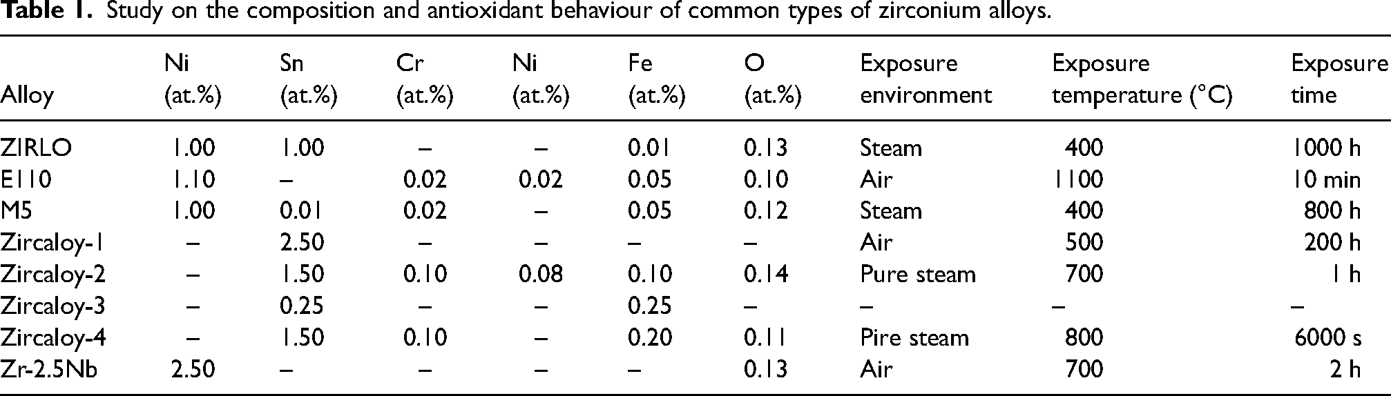
The Fukushima nuclear power plant leakage has caused serious environmental pollution. In order to deal with the loss of coolant accidents, accident-resistant fuel has been paid more and more attention.1,2 Scholars and researchers around the world have studied metal zirconium and believe that zirconium can be used as an anti-accident fuel cladding material. This is due to the fact that the metal Zr has a high melting point (1852.0 °C), a low density (6.49 g/cm3), good electrical and thermal conductivities (electrical conductivity: 0.0236 × 10⁶/(cm·Ω), thermal conductivity: 22.6 W/(m·K)), corrosion resistance and high-temperature strength. Unfortunately, zirconium is difficult to use directly in the nuclear industry due to its very poor oxidation resistance. Zirconium alloy is considered the most promising accident-resistant fuel cladding material because of its good oxidation resistance. 3 Adding appropriate alloying elements (Nb, Sn, Cr, Ni, and Fe) to a zirconium matrix can increase its service temperature to a certain extent. According to the information provided in Table 1, zirconium base alloys have better oxidation resistance and higher service temperature than pure zirconium. However, when the ambient temperature exceeds 800 °C, the service life of zirconium and its alloys is significantly reduced. This is because the addition of a small amount of alloying elements cannot quickly form a continuous oxide film on the surface of the substrate exposed to high temperatures. At the same time, an excessive increase in alloying element content usually reduces the mechanical properties of the material. 2 Fortunately, surface coating technology can significantly improve the oxidation resistance of materials without changing their physical and chemical properties.
Study on the composition and antioxidant behaviour of common types of zirconium alloys.
The oxidation resistance of zirconium alloy can be effectively enhanced by coating on its surface.4–8 The main purpose of zirconium alloy fuel cladding is to improve the oxidation resistance of the substrate and reduce the generation of hydrogen.9–11 At present, there are many functional coatings developed for zirconium-based materials. Among them, chromium coating, composite coating, multilayer coating and MAX phase coating (Ti3SiC2, Ti2AlC, etc.) have been widely used and studied.12–15 Chromium-clad zirconium alloys exhibit excellent oxidation resistance in high-temperature vapours.3,16–18 The results show that CrSi coating can effectively protect zirconium alloys in high-temperature air at 1160 °C. 19 Nitrides are used as anti-oxidation coatings because of their good anti-oxidation properties.20,21 At present, there are few studies on ZrSi2- and CrAlSiN-coated zirconium alloys. Kim et al. 22 and Zhu et al. 23 carried out oxidation experiments in high-temperature steam at 1200 °C and found that the oxidation of uncoated zirconium alloys is much more serious than that of coated zirconium alloys. Recently, relevant researchers have proposed a MAX phase coating with light weight, good toughness and oxidation resistance, which is considered a promising fuel cladding material.24–26 FeCrAl alloys have received particular attention because of their good machinability. 27
In this work, the surface coating protection technology of zirconium alloys is reviewed. The microstructure, oxidation kinetics and oxidation resistance of different kinds of coated zirconium alloys in different high-temperature environments were analysed, and their oxidation behaviour and failure mechanism were also analysed. Finally, the main problems and challenges of zirconium alloy surface coating technology were also summarised and prospected.
Anti-oxidation coating on the surface of zirconium alloy
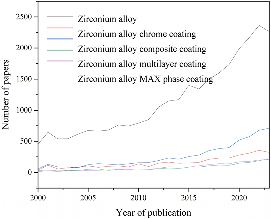
Number of zirconium alloy antioxidant coating papers by keyword in Scopus (2000–2023)
Source: Elsevier Ltd.
The types and number of research-related papers from 2000 to 2023 are shown in the chart above. The main institutions and main authors engaged in zirconium alloy-related fields are the School of Materials Science and Engineering, Jiangsu University of Science and Technology, Zhenjiang, China (Ziyu Zhang et al.); Department of Chemistry, University of Tennessee, USA (Breanna K. Vestal et al.), China Nuclear Power Technology Research Institute, Shenzhen, Guangdong, China (Jing Hu et al.), Nuclear Engineering Department, North Carolina State University, Raleigh, NC, USA (Elizabeth Kautz et al.); major institutions and lead authors engaged in zirconium alloy chromium coating-related fields are the Innovation Research Team for Advanced Ceramics, Institute of Nuclear Physics and Chemistry, China Academy of Engineering Physics, Mianyang, China (Xiaochun Han et al.); Key Lab of Materials Modification by Laser, Ion and Electron Beams (Ministry of Education), School of Materials Science and Engineering, Dalian University of Technology, Dalian, China (Xiaogang Hu et al.); LWR Fuel Technology Division, KAERI, 989-111, Daedeok-daero, Yuseong-gu, Daejeon 305-353, Republic of Korea (Jung-Hwan Park et al.); the main institutions and main authors engaged in zirconium alloy composite coating-related fields are Canadian Nuclear Laboratories, Chalk River Laboratories, Ontario, Canada (K. Daub et al.); School of Nuclear Science and Technology, Xi’an Jiaotong University, Xi’an, China (Junkai Liu et al.); Innovation Research Team for Advanced Ceramics, Institute of Nuclear Physics and Chemistry, China Academy of Engineering Physics, Mianyang, China (Song Zeng et al.); the main institutions and main authors engaged in the fields related to zirconium alloy multilayer coating are the Key Laboratory of Beam Technology of the Ministry of Education, College of Nuclear Science and Technology, Beijing Normal University, Beijing, China (Xingping Wang et al.); School of Nuclear Science and Technology, Xi’an Jiaotong University, Xi’an, China (Junkai Liu et al.); the main institutions and main authors engaged in the field of zirconium alloy MAX phase coating are the Institute for Applied Materials (IAM-AWP), Karlsruhe Institute of Technology (KIT), D-76021 Karlsruhe, Germany (Chongchong Tang et al.); and Department of Engineering Physics, University of Wisconsin-Madison, Madison, WI 53706, USA (Hwasung Yeom et al.).
Chromium coating
Chromium coating is one of the most promising antioxidant materials because of its good antioxidant properties. Park et al. 28 carried out the oxidation experiment of chromium-plated Zr-4 alloy in 1200 °C steam for 2000 s. Figure 1(a) is a cross-section image of a chrome-coated Zr-4 alloy. The results show that the chromium coating is compact and uniform in structure, and the coating is well combined with the substrate. Figures 1(b) and (c) show the optical micrographs of uncoated and chrome-coated Zr-4 alloys oxidised at 1200 °C in high-temperature steam for 2000 s. After high-temperature oxidation, the prior-β forms on the surface of both Zr-4 and chrome-plated Zr-4 alloys, ZrO2 and α-Zr(O) also form on the surface of Zr-4 alloys, and Cr2O3 oxide films form on the surface of chrome-plated Zr-4 alloys. Therefore, chromium coating can prevent oxygen diffusion and inhibit the generation of α-Zr(O). Figure 2(a) shows that in terms of mass gain, the uncoated Zr-4 alloy is about twice that of the chrome-plated Zr-4 alloy, which indicates that the chrome-plated Zr-4 alloy has good high-temperature oxidation resistance. Kim et al. 29 also reported the oxidation state of chromium coating at 1200 °C. Figures 1(d) and (e) show cross-section images of chrome-plated Zr-4 alloy prepared by three-dimensional laser technology after steam oxidation. It shows that after high-temperature oxidation, the oxidation layer thickness of the chromium coating on the zirconium alloy is relatively thin and no cracks are observed. Figure 1(f) shows that a thicker ZrO2 layer forms on the surface of the bare Zr-4 alloy. Wang et al. 30 oxidised chromium-plated Zr-4 alloy in steam at 1200 °C for 1 h. Figure 1(g) shows that a columnar ZrO2 layer forms inside the uncoated zirconium alloy, while no ZrO2 forms outside the chromium-coated zirconium alloy. The concentration distribution of O, Cr and Zr elements along the scanning line in Figure 1(h) is shown in Figure 2(b). The results show that there is almost no internal diffusion of oxygen during oxidation. Figure 1(i) shows the surface morphology of the chromium coating after oxidation at 1200 °C for 2000 s. The oxidation surface is relatively dense, and no micro-cracks and pores are observed, which effectively prevents the internal diffusion of oxygen.
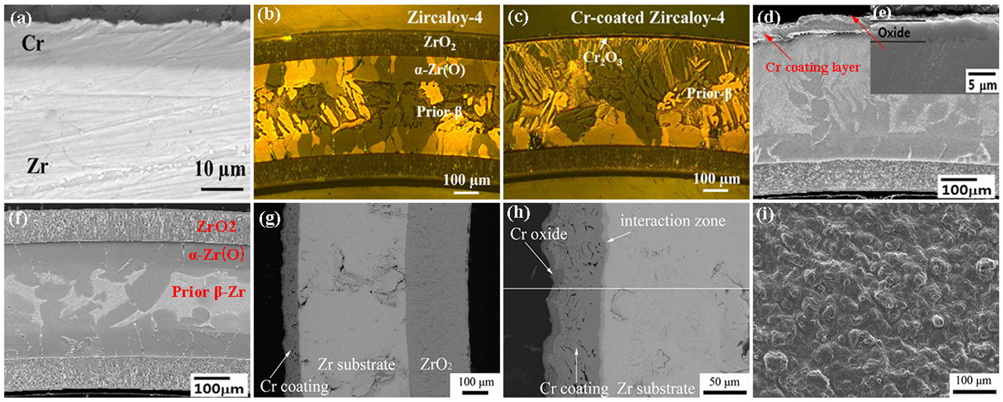
Surface and cross-section morphology of chrome-plated and uncoated Zr-4 alloys before and after oxidation: (a) cross-sectional images of chromium-coated zirconium alloys; (b, c) reflected light micrographs of oxidised bare zirconium alloys and chromium-coated zirconium alloys; (d, e) scanning electron microscopy (SEM) images of chromium-coated zirconium alloy after oxidation; (f) cross-section images of oxidised zirconium alloys; (g, h) cross-section images of Cr coating before and after oxidation; (i) surface image of Cr coating after oxidation. (a–i) Reproduced with permission,28–30 respectively. Copyright 2015 Elsevier Ltd and 2018 Elsevier Ltd.
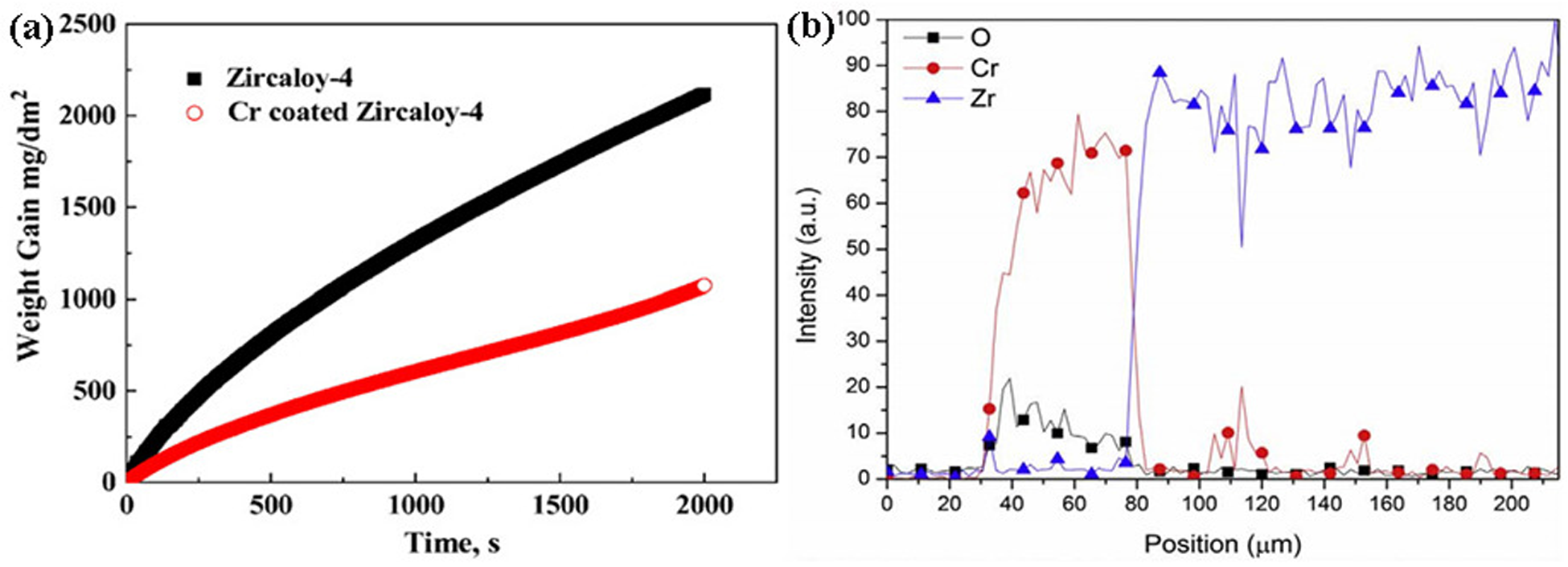
Mass gain and element distribution of uncoated zirconium alloys and chromium-coated zirconium alloys after steam oxidation at 1200 °C for 2000 s: (a) mass gain curves with oxidation time; (b) the concentration profile of O, Cr, and Zr elements along the scan line in Figure 1(h). Reproduced with permission from Wang et al. 30 Copyright 2018 Elsevier Ltd.
In a high-temperature steam environment, an oxidation–reduction reaction will occur between the chromium coating and the zirconium substrate, which reduces the corrosion resistance of the chromium coating. Han et al. 31 reported the oxidation behaviour of chromium-coated zirconium alloy at 1000 °C to 1200 °C. Figure 3(a) shows that the Cr coating has a dense and uniform structure, no micro-cracks in the cross-section are found, and there is a good adhesion between the coating and the substrate. Figure 3(b) shows that after oxidation, a dense and uniform Cr2O3 layer forms on the surface of the chromium coating, and the Cr2O3 layer has a good adhesion with the remaining chromium layer. Figure 3(c) shows that after 1 h oxidation at 1100 °C, the oxide layer thickens and its thickness becomes very uneven due to different crystal orientations. The remaining chromium is almost exhausted, but the zirconium substrate is intact. It can be seen from Figure 3(d) that after oxidation at 1200 °C for 1 h, from the surface of the coating perpendicular to the substrate, the oxide layers are successively Cr2O3 layer, residual Cr layer, intermetallic compound ZrxCry layer and ZrO2 layer from the outside to the inside. The chromium coating is almost completely oxidised to Cr2O3 in a high-temperature steam environment. Meanwhile, the oxygen ions become more active and then diffuse with Zr2+ to form ZrO2. With the progress of the oxidation reaction, Cr3+ will undergo a reduction reaction to form a metal chromium layer.
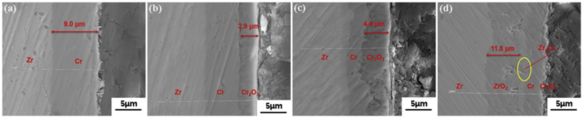
Cross-section images of chrome-coated Zr-4 alloy before and after oxidation at different temperatures for 1 h: (a) chrome-coated Zr-4 alloy; (b) 1000 °C; (c) 1100 °C; (d) 1200 °C. Reproduced with permission from Han et al. 31 Copyright 2019 Elsevier Ltd.
Han et al. 32 reported the change of oxidation time of a chromium-coated zirconium alloy in steam at 1200 °C and studied the redox reaction of chromium-coated zirconium alloy. Figure 4 shows the variation curve of Cr2O3 layer thickness and ZrO2 layer thickness with oxidation time. Figure 4(a) shows that the thickness of the Cr2O3 layer rises in a parabolic pattern and reaches the maximum thickness at 75 min. When the oxidation time is 75 to 120 min, the thickness of the Cr2O3 layer decreases sharply with increasing oxidation time. When the oxidation time exceeds 120 min, the thickness of the Cr2O3 layer is basically unchanged, and the thickness of the ZrO2 layer gradually increases. As can be seen from Figure 4(b), the reaction of uncoated zirconium alloy is very strong, and the thickness of the ZrO2 layer rises sharply. The oxidation rate of uncoated zirconium alloys is very high. Therefore, an oxidation–reduction reaction is inevitable during the oxidation process of chromium coating. Although the chromium coating is consumed, the Cr2O3 layer inhibits the rapid diffusion of oxygen atoms, which indicates that the chrome-plated Zr-4 alloy has excellent properties.
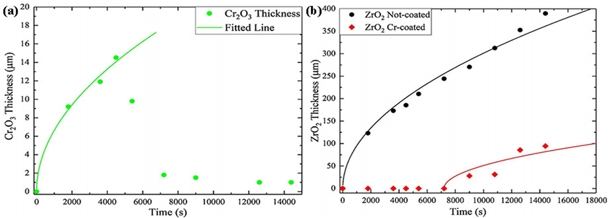
Thickness curve of Cr2O3 layer and ZrO2 layer with oxidation time: (a) thickness curve of chromium-coated zirconium alloy Cr2O3 layer; (b) ZrO2 layer thickness curves on the surface of uncoated zirconium alloys and chromium-coated zirconium alloys. Reproduced with permission from Han et al. 32 Copyright 2020 Elsevier Ltd.
Hu et al. 33 prepared a 20 mm thick chromium coating on Zr-4 alloy and studied its behaviour after 1 h oxidation in air at 1000 °C, 1100 °C and 1200 °C. Figure 5 shows the scanning electron microscopy (SEM) images after oxidation at different temperatures for 1 h. Figures 5(a) and (b) show that the cross-section morphology of the coating changes little after oxidation at 1000 °C for 1 h and a thin oxide layer forms on the chromium coating. Figure 5(c) shows that when the temperature is 1100 °C, the thickness of the oxide layer thickens and a large bubble cavity appears, and the thickness of the Cr–Zr layer also thickens. As can be seen from Figure 5(d), when the oxidation temperature is 1200 °C, serious oxidation occurs in chrome-plated zirconium alloy. Oxygen atoms pass through the chromium coating, causing serious damage to the zirconium alloy matrix, and large bubble-like cavities appear in the zirconium alloy matrix. Therefore, chromium-plated zirconium alloy has good oxidation resistance in the initial oxidation stage.
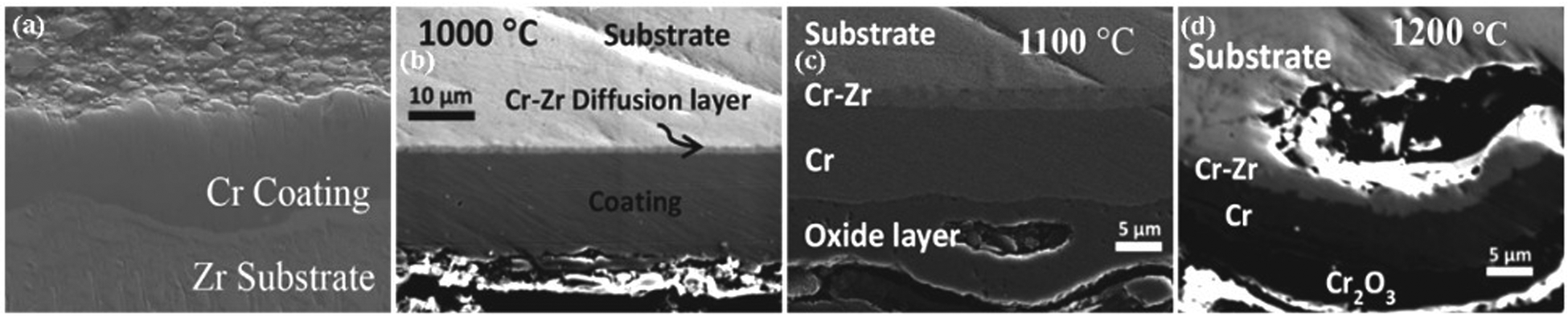
Cross-section image of chromium-coated zirconium alloy oxidised at different temperatures for 1 h: (a) before oxidation; (b) 1000 °C; (c) 1100 °C; (d) 1200 °C. Reproduced with permission from Hu et al. 33 Copyright 2019 Elsevier Ltd.
Huang et al. 34 also prepared chromium-plated Zr-4 alloys and carried out oxidation experiments in air at 1000 °C, 1100 °C and 1200 °C. Figure 6(a) shows that the mass gain of uncoated zirconium alloys is several times that of chromium-coated zirconium alloys when the temperature rises. Figure 6(b) shows that the thickness of the Cr–Zr layer in the chrome-coated zirconium alloy increases linearly. The formation of Cr2Zr enhances the adhesion of the system. Therefore, chromium plating can better protect the zirconium matrix.
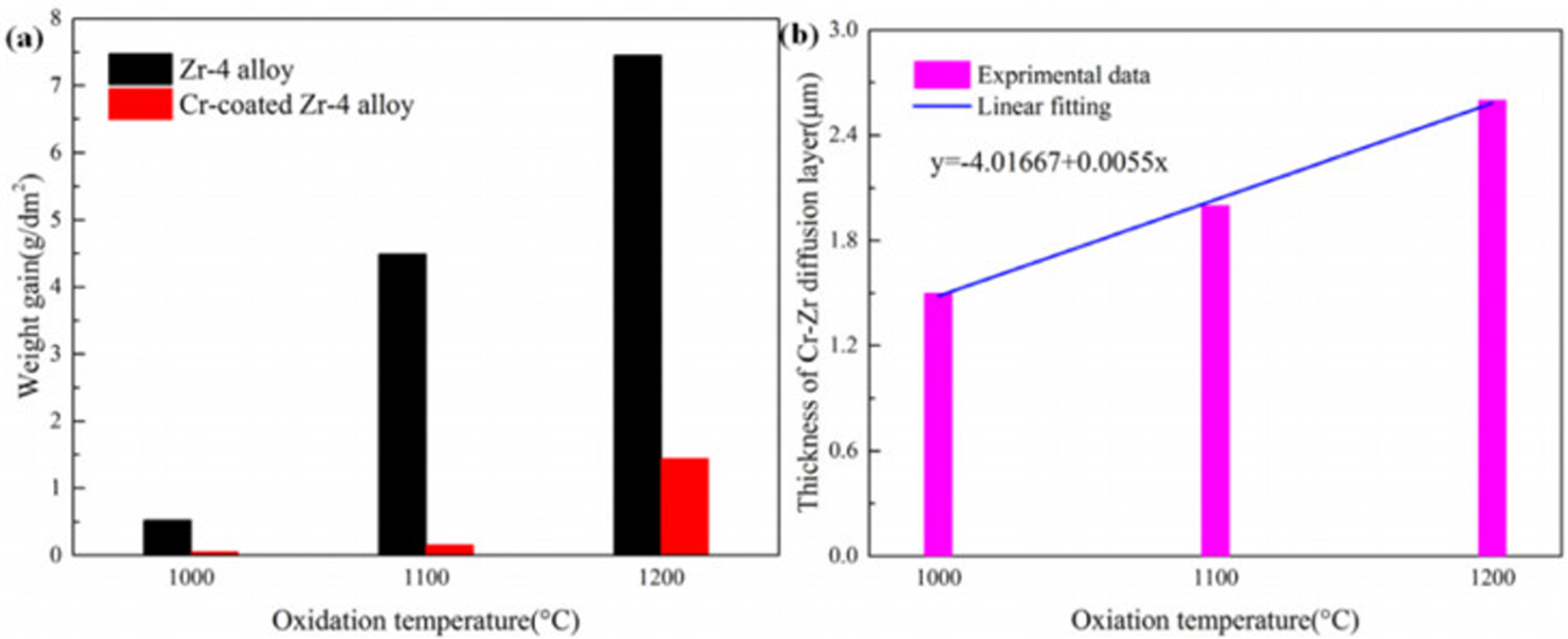
Mass gain (a) and thickness (b) of Cr–Zr layer of chrome-plated Zr-4 alloy after oxidation in air under different conditions. Reproduced with permission from Huang et al. 34 Copyright 2022 Elsevier Ltd.
Composite coating
The composite coating on the surface of zirconium alloy also has certain high-temperature oxidation resistance. Daub et al. 35 deposited 2 to 4 mm thick AlCrN, TiAlN and CrN coatings on Zr-4 alloy and studied their oxidation resistance. Figure 7 shows the cross sections of Zr-4 alloys with different coatings after oxidation at 1100 °C for 15 min. Figure 7(a) shows that the exposed Zr-4 alloy is heavily oxidised, with many cracks and pores in the oxide layer. Figure 7(b) shows that large cracks are also observed on the AlCrN coating, but the coating is not completely consumed or shed. The oxide film is basically zirconia and alumina. Figure 7(c) shows that the TiAlN coating is severely oxidised after oxidation at 1100 °C for 15 min, the formation of a large amount of zirconia is the main cause of coating cracking. Notably, Figure 7(d) shows that the CrN coating has good oxidation resistance, with cracks observed only in local locations and small amounts of zirconia forms under the coating. Therefore, AlCrN, TiAlN and CrN coatings can protect zirconium alloy from oxidation in 1100 °C steam, and CrN coating has the best oxidation resistance.
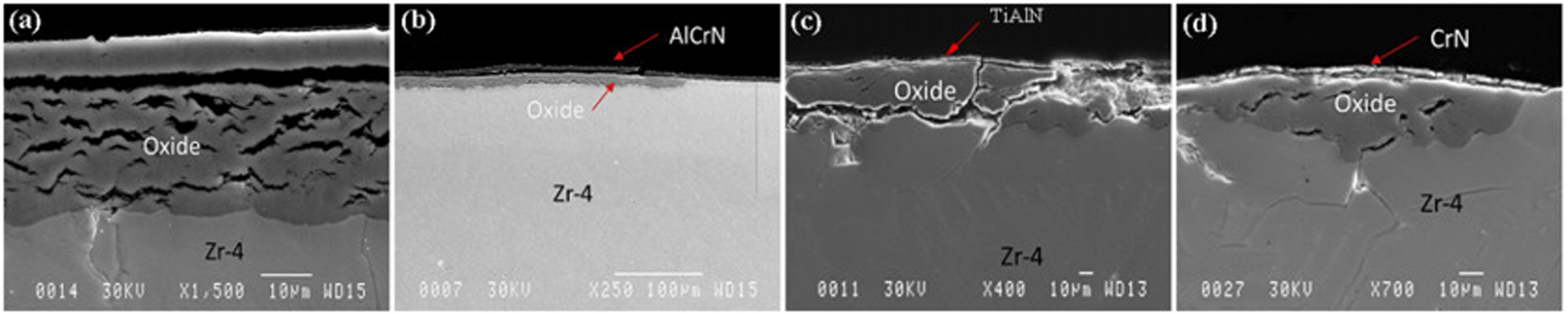
Scanning electron microscopy (SEM) cross-section of different coated Zr-4 alloys after steam oxidation at 1100 °C for 15 min: (a) bare Zr-4; (b) AlCrN; (c) TiAlN; (d) CrN. Reproduced with permission. 35 Copyright 2015 Elsevier Ltd.
Zeng et al. 36 deposited a layer of CrSi coating on the Zr-4 alloy and studied its oxidation resistance after oxidising for 1 h in steam at 1200 °C. Figures 8(a) and (b) show that the CrSi coating is an irregular polygon without a shedding phenomenon. After 1 h oxidation at 1200 °C, the morphology of Cr2O3 on the surface of CrSi coating is similar to that of chromium plating. 31 Figure 8(c) shows that the zirconium substrate on one side of the coating is not oxidised, while the uncoated zirconium substrate has been oxidised to form a thicker zirconia layer. Figure 8(d) shows that the Cr2O3 layer generated on the surface of the coating is compact and uniform, without obvious cracks and spalling, which inhibits the diffusion of oxygen to the Zr-4 alloy. Liu et al. 37 analysed the oxidation behaviour of CrN-coated Zr-4 alloy after oxidation at 1200 °C for 1 h. Figures 8(e) to (g) show the SEM images of CrN coating after oxidation at 1200 °C for 1 h. Figure 8(e) shows that the surface of the oxidised coating is relatively uniform and smooth, and the grain size is large. Figure 8(f) shows that the CrN coating has a good adhesion to the zirconium matrix, no cracks or shedding are observed, and the CrN coating shows a good oxidation resistance. In addition, the CrN coating is not completely oxidised, the oxide layer forms on the outside, the nitride layer forms on the inside, and the zirconium substrate is not oxidised, as shown in Figure 8(g).
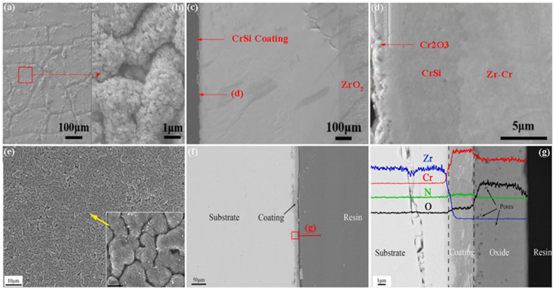
Microstructures of CrSi coating (a–d) and CrN coating (e–g) after oxidation in high-temperature steam at 1200 °C for 1 h. (a, b) Surface morphology of oxidised CrSi coating; (c) cross-section morphology of oxidised CrSi coating; (d) high magnification image of (c); (e) surface morphology of oxidised CrN coating; (f) cross-section morphology of oxidised CrN coating; (g) high magnification image of (f). (a–g) Reproduced with permission,36,37 respectively. Copyright 2021 Elsevier Ltd.
Liu et al. 38 deposited CrAlN and CrAlSiN coatings on Zr-4 alloy and investigated their oxidation resistance after oxidation in high-temperature steam at 1200 °C for 1 h. As shown in Figure 9(a), oxygen atoms are internally diffused through the CrAlN coating to form a dense and uniform zirconia layer on the substrate surface. As can be seen from Figure 9(b), a chromium-rich aluminium-rich multilayer structure appears on the surface of the ZrO2 layer, and a layer of CrAlN about 2 μm thick remains in the middle of the oxide layer, indicating that the coating is not completely consumed. It can be seen from Figures 9(c) and (d) that uniform and dense ZrO2 forms on the surface of the uncoated Zr-4 alloy after oxidation. The mixed layer of nitride, alumina and silica formed on the surface of the ZrO2 layer can better protect the Zr-4 alloy substrate. Because the SiO2 formed after the oxidation of CrAlSiN coating is easy to crack, its oxidation resistance is not as good as that of CrAlN coating. Therefore, the CrN coating has the best oxidation resistance in high-temperature steam at 1200 °C, followed by CrSi coating and CrAlN coating, and CrAlSiN coating is the worst.
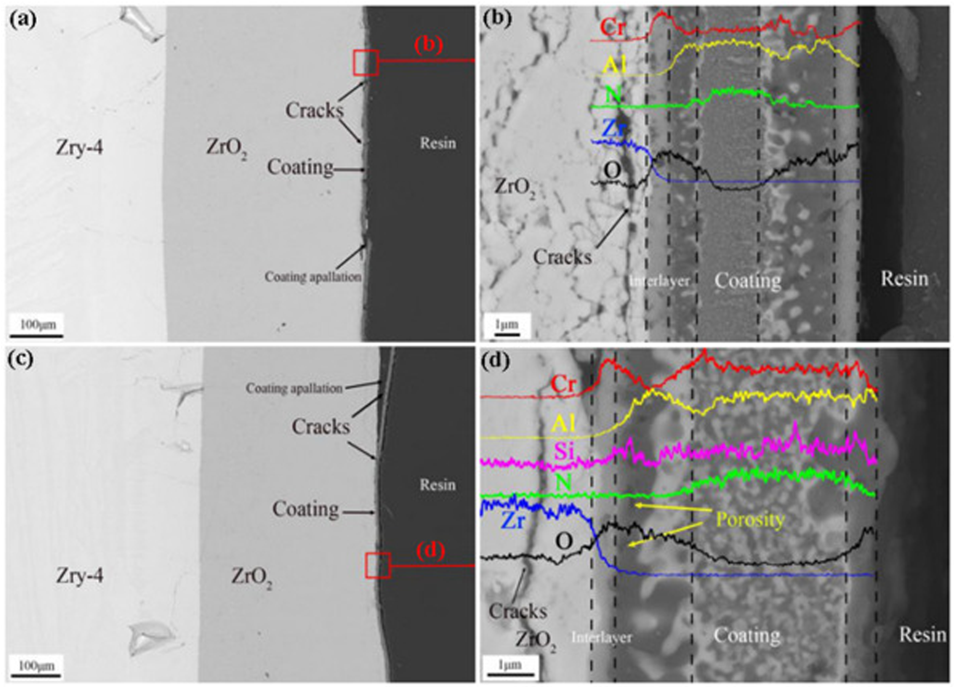
Cross-sectional scanning electron microscopy (SEM) images and element concentration profiles of CrAlN and CrAlSiN coatings on Zr-4 alloys after oxidation in high-temperature steam at 1200 °C for 1 h: (a) CrAlN coating; (b) element concentration profiles of oxidised CrAlN coating; (c) CrAlSiN coating; (d) element concentration profiles of oxidised CrAlSiN coating. Reproduced with permission from Liu et al. 38 Copyright 2020 Elsevier Ltd.
Multilayer coating
At present, the reported multilayer coatings on zirconium alloys mainly include Cr–CrN/TiSiN coatings, ZrO2/Cr coatings and ZrO2/FeCrAl coatings. The performance of the coating from strong to weak is Cr–CrN/TiSiN coating, ZrO2/Cr coating, and ZrO2/FeCrAl coating. Wang et al. 39 studied the state of ZrO2/FeCrAl-coated zirconium alloy after 3800 s oxidation at 1000 °C. Figure 10 shows the microstructure of the multilayer coating after oxidation of zirconium alloy. Figures 10(a) and (b) show that the coating surface is relatively smooth without micro-cracks. Figure 10(c) shows that the coating still maintains a double-layer structure and the zirconium matrix is not oxidised in high-temperature steam. The FeCrAl layer is uniform, dense and complete in structure, some micro-cracks are observed in the ZrO2 layer. The adhesion between ZrO2/FeCrAl coating and zirconium substrate is still good. The oxidation rate of ZrO2/FeCrAl coating is the lowest in the whole oxidation process, as shown in Figures 11(a) and (b). Wang et al. 40 analysed the oxidation resistance of ZrO2/Cr-coated zirconium alloy at 1000 °C and 1100 °C. After oxidation at 1000 °C, Cr2O3 forms on the surface, chromium slag is not completely consumed under the coating, and the zirconium matrix is not oxidised, as shown in Figures 10(d) and (e). After oxidation at 1100 °C, Cr2O3 forms on the coating surface, ZrO2 forms on the zirconium substrate, and part of the zirconium substrate is oxidised. Figures 11(c) and (d) show that the parabolic rate constant of the uncoated zirconium alloy is much larger than that of the ZrO2/Cr-coated zirconium alloy. Liu et al. 41 prepared a Cr–CrN/TiSiN-coated zirconium alloy and studied its oxidation resistance in high-temperature steam at 1200 °C for 1500 s and 3600 s, respectively. Figure 10(f) shows that chromium atoms and titanium atoms in the outer layer of the coating diffuse outward to form chromium-rich regions and titanium-rich regions. During oxidation, oxygen atoms diffuse inward and react with chromium and titanium atoms to form a mixed oxide layer. The silicon atoms diffuse outwards and react with oxygen to form SiO2, which enhances the adhesion of the coating to the zirconium alloy. Figure 10(g) shows that the outward diffusion rate of titanium atoms increases and then is oxidised to generate a mixed oxide layer. There are many large cracks in the middle area of the coating. In addition, the diffusion of chromium zirconium is serious, and oxygen atoms enter the zirconium substrate and lead to local oxidation of the zirconium substrate. Figure 11(e) shows that the growth rate of the uncoated zirconium alloy during the entire oxidation process is several times that of the Cr–CrN/TiSiN coating. After oxidation at 1200 °C for 1500 s, there is no obvious oxidation on the coated zirconium alloy. After oxidation at 1200 °C for 3600 s, there is light oxidation in the four corners of the coated zirconium alloy. Therefore, the formation of chromium oxide, titanium oxide and silicon dioxide on the surface of Cr–CrN/TiSiN coating effectively inhibits the inward diffusion of oxygen and significantly improves the corrosion resistance of zirconium substrate in high-temperature steam.
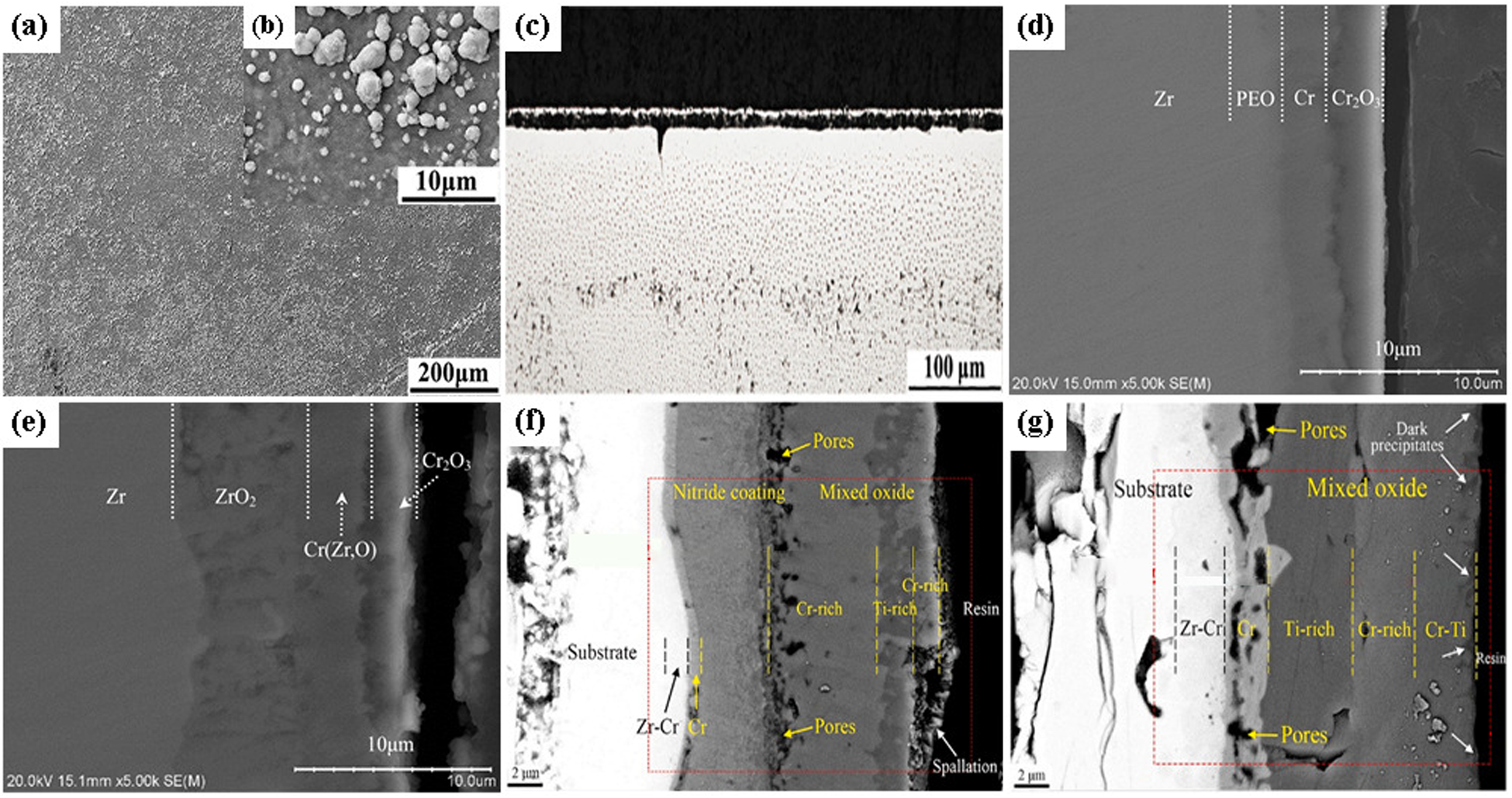
Microstructure of multilayer coated zirconium alloy after oxidation: (a–c) scanning electron microscopy (SEM) image of ZrO2/FeCrAl coating; (d, e) microscopic images of ZrO2/Cr coating; microscopic image of (f, g) Cr–CrN/TiSiN coating. (a–g) Reproduced with permission,39–41 respectively. Copyright 2020 Korean Nuclear Society, 2014 Elsevier Ltd and 2021 Elsevier Ltd.
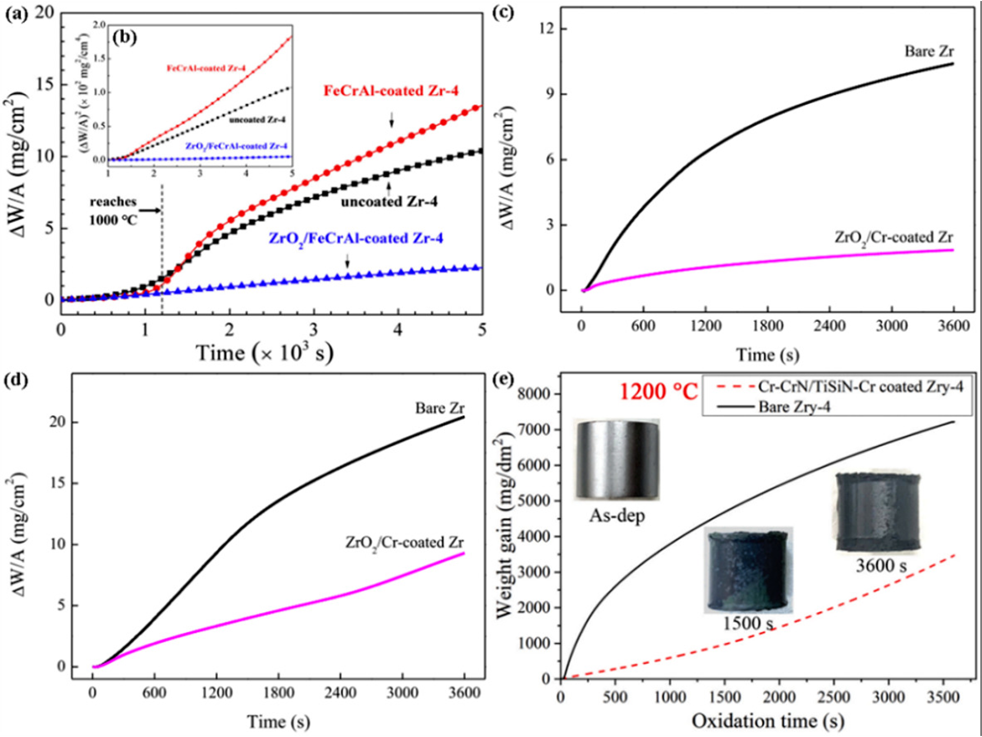
Mass gain and square of mass gain of oxidised bare Zr, uncoated Zr-4 alloy and coated sample under different conditions: (a, b) uncoated Zr-4 alloy, FeCrAl-coated Zr-4 alloy, and ZrO2/FeCrAl-coated Zr-4 alloy; (c, d) bare Zr and ZrO2/Cr-coated Zr; (e) bare Zr-4 alloy and Cr–CrN/TiSiN–Cr-coated Zr-4 alloy. (a–e) Reproduced with permission,39–41 respectively. Copyright 2020 Korean Nuclear Society, 2014 Elsevier Ltd and 2021 Elsevier Ltd.
MAX phase coating
In light water reactors, MAX phase coating is also often used for accident-resistant fuel cladding. MAX phase is a ternary structure compound, which combines the advantages of ceramics and metals and shows excellent oxidation resistance. Relevant scholars have reported Cr2AlC coating, Cr/Cr2AlC coating and Ti2AlC coating in high-temperature steam. It shows that the above coatings have good high-temperature oxidation resistance, and Ti2AlC coating has the best oxidation resistance. Tang et al. 42 prepared Cr2AlC MAX phase coating on Zr-4 alloy and studied its oxidation resistance at 1000 °C. Figure 12(a) shows that a dense and uniform α-Al2O3 layer forms, which well inhibits the internal diffusion of oxygen atoms. Figure 13(a) shows that the oxidation of Cr2AlC coating generates Al2O3 and CrCx phases, and the oxidation of Cr/Cr2AlC coating generates Cr2O3, Al2O3 and CrCx phases. In Figure 12(b), the chromium layer is oxidised easily, and high-temperature steam passes through the chromium oxide layer and causes oxidation and cracking of the Cr2AlC coating. Fortunately, dense Al2O3 fills the crack in time, effectively inhibiting the further oxidation of high-temperature steam. Figure 12(c) shows that the exposed Zr-4 alloy is oxidised to a layer of zirconia ZrO2 with a thickness of 135 μm. At the same time, many pores and cracks (see Figure 12(d)) form on the ZrO2 layer, indicating that the Zr-4 alloy has been severely oxidised. Yeom et al. 25 deposited Cr2AlC coating on Zr-702 alloy and studied its oxidation behaviour in air at 1200 °C. Figure 13(b) shows the X-ray diffraction (XRD) patterns of the Cr2AlC-coated Zr-702 alloy oxidised in high-temperature air at 1200 °C for different times. After oxidation for 30 min, Cr2O3 and ZrO2 form. After oxidation for 60 min, the content of ZrO2 increases, indicating that the Zr-702 alloy substrate has been oxidised at this time. Figures 12(e) to (g) show that there is dense alumina formation, the middle layer is mostly Cr7C3, and there are a large number of micropores. The interfacial layer still maintains a relatively dense structure. Therefore, the Cr2AlC coating and Cr/Cr2AlC coating have good oxidation resistance in high-temperature environments.
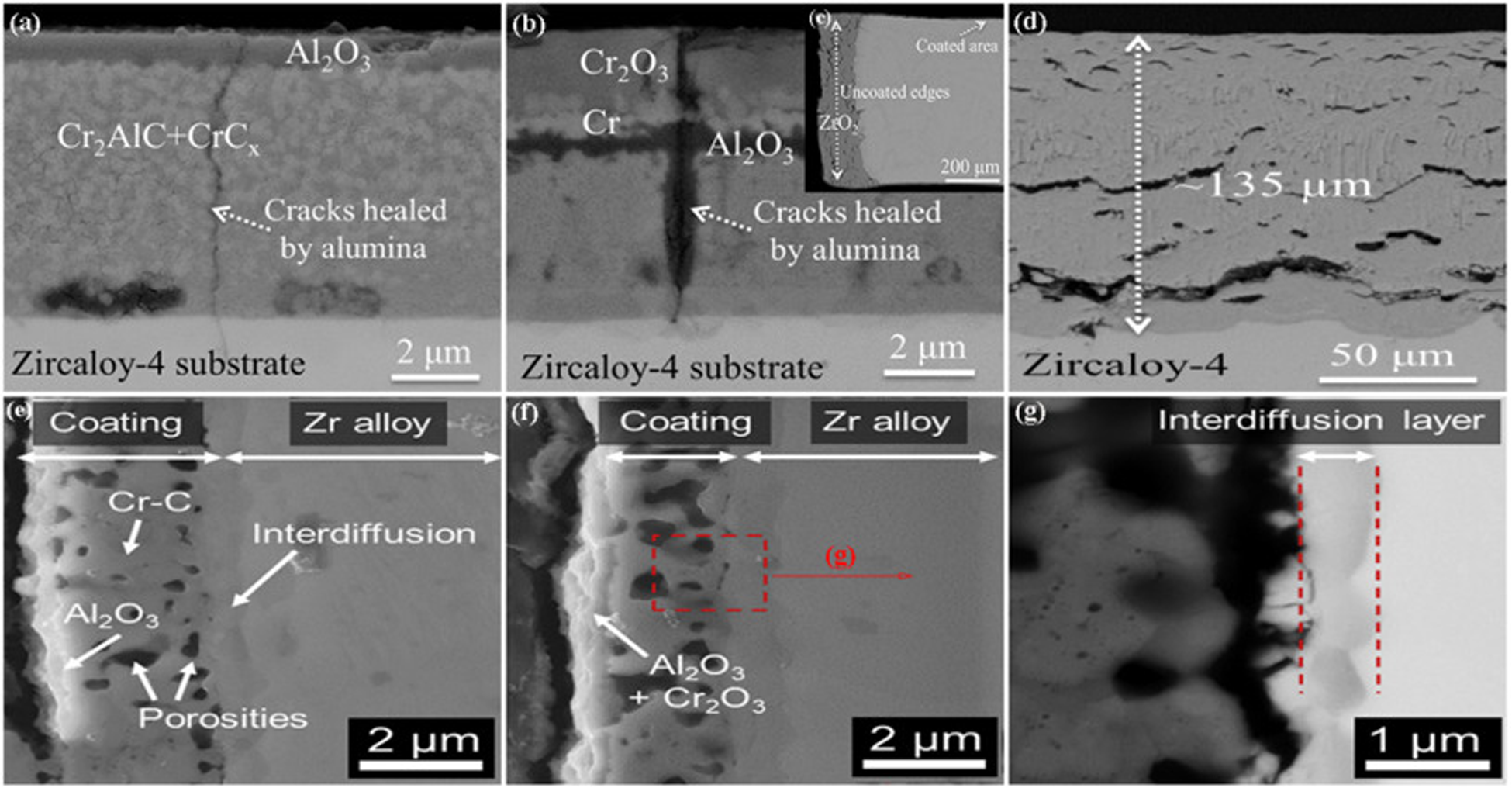
BSE images of zirconium alloys with different coatings oxidised in high-temperature steam at 1000 °C for 1 h: (a) Cr2AlC coating; (b) Cr/Cr2AlC coating; (c) bare Zr-4 alloy; (d) high magnification scanning electron microscopy (SEM) image of (c). SEM morphology of Cr2AlC-coated Zr-702 alloy after oxidation in air at 1200 °C for different times: (e) 15 min; (f) 60 min; (g) high magnification image of the micro area in (f). (a–g) Reproduced with permission.25,42 Copyright 2020 Elsevier Ltd and 2016 Elsevier Ltd.
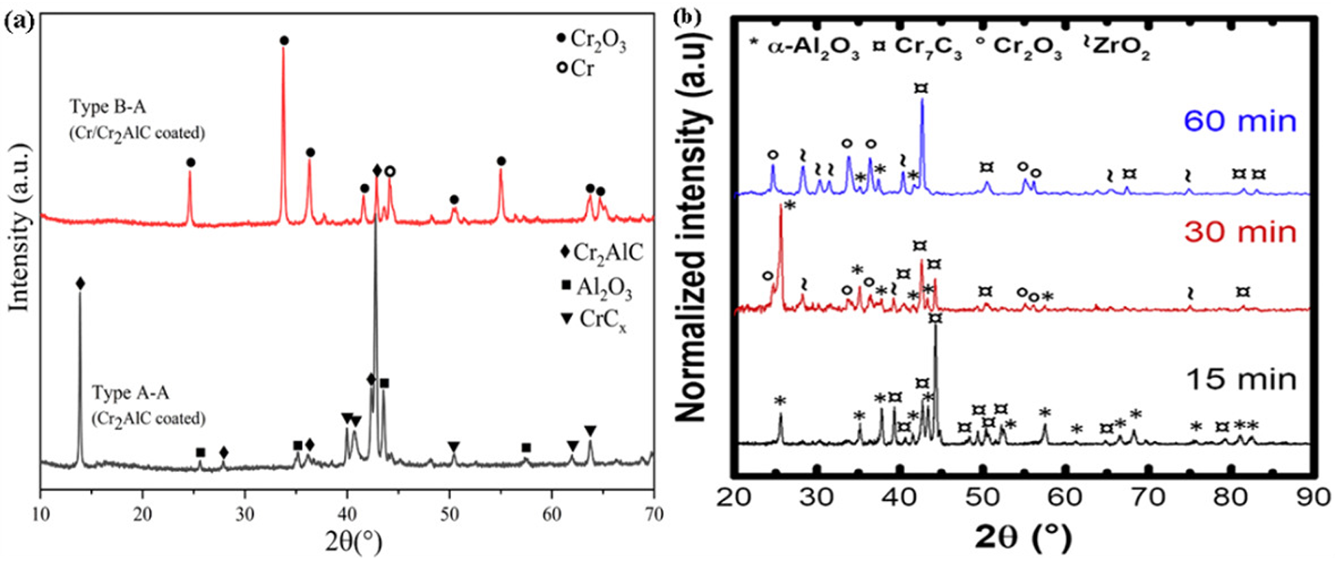
X-ray diffraction (XRD) patterns of zirconium alloys with different kinds of coatings after oxidation at high temperatures: (a) XRD spectra of Cr2AlC and Cr/Cr2AlC-coated zirconium alloys after oxidation in 1000 °C high-temperature steam for 1 h; (b) XRD patterns of Cr2AlC coating Zr-702 oxidised in air at 1200 °C for different times. (a, b) Reproduced with permission,25,42 respectively. Copyright 2020 Elsevier Ltd and 2016 Elsevier Ltd.
Li et al. 43 deposited a Ti2AlC coating on zirconium alloy and studied its oxidation resistance in steam at 1100 °C and 1200 °C. Figure 14 shows the SEM images of Ti2AlC-coated zirconium alloy after oxidation in steam at different temperatures. Figure 14(a) shows that after oxidation at 1100 °C for 10 min, the coating surface is relatively loose, and large cracks appear between the oxide layer and the coating. Although the coating structure changes, the zirconium substrate is still not oxidised. After oxidation at 1200 °C for 5 min, a typical three-layer structure is observed, namely Ti–Al oxide mixture layer, Al oxide layer and Ti oxide layer from the outside to the inside, as shown in Figure 14(b). The Zr–Al diffusion layer appears near the zirconium substrate, and the coating is not completely oxidised. Figures 14(c) and (d) show that the coated zirconium alloy suffered a violent oxidation after oxidation at 1200 °C for 10 min, all the surface oxides are shed, and a thicker Zr–O diffusion layer forms on the substrate surface. Tang et al. 24 carried out an oxidation experiment on Ti2AlC-coated zirconium alloys in high-temperature steam at 1400 °C and 1500 °C. As shown in Figures 14(e) and (f), a dense and uniform Al2O3 forms on the surface of the coating, which has good adhesion with the zirconium substrate. The growth rate of Al2O3 is relatively slow, Al2TiO5 is generated, and the zirconium substrate is not oxidised. Figures 14(g) and (h) show that the surface of the coating is granular and has some micro-cracks. After exposed at 1500 °C for 1 h, the Ti2AlC-coated zirconium alloy is seriously damaged and part of the substrate is oxidised. Based on the above analysis, the coating can provide a satisfactory oxidation protection to the substrate at a temperature of 1400 °C.
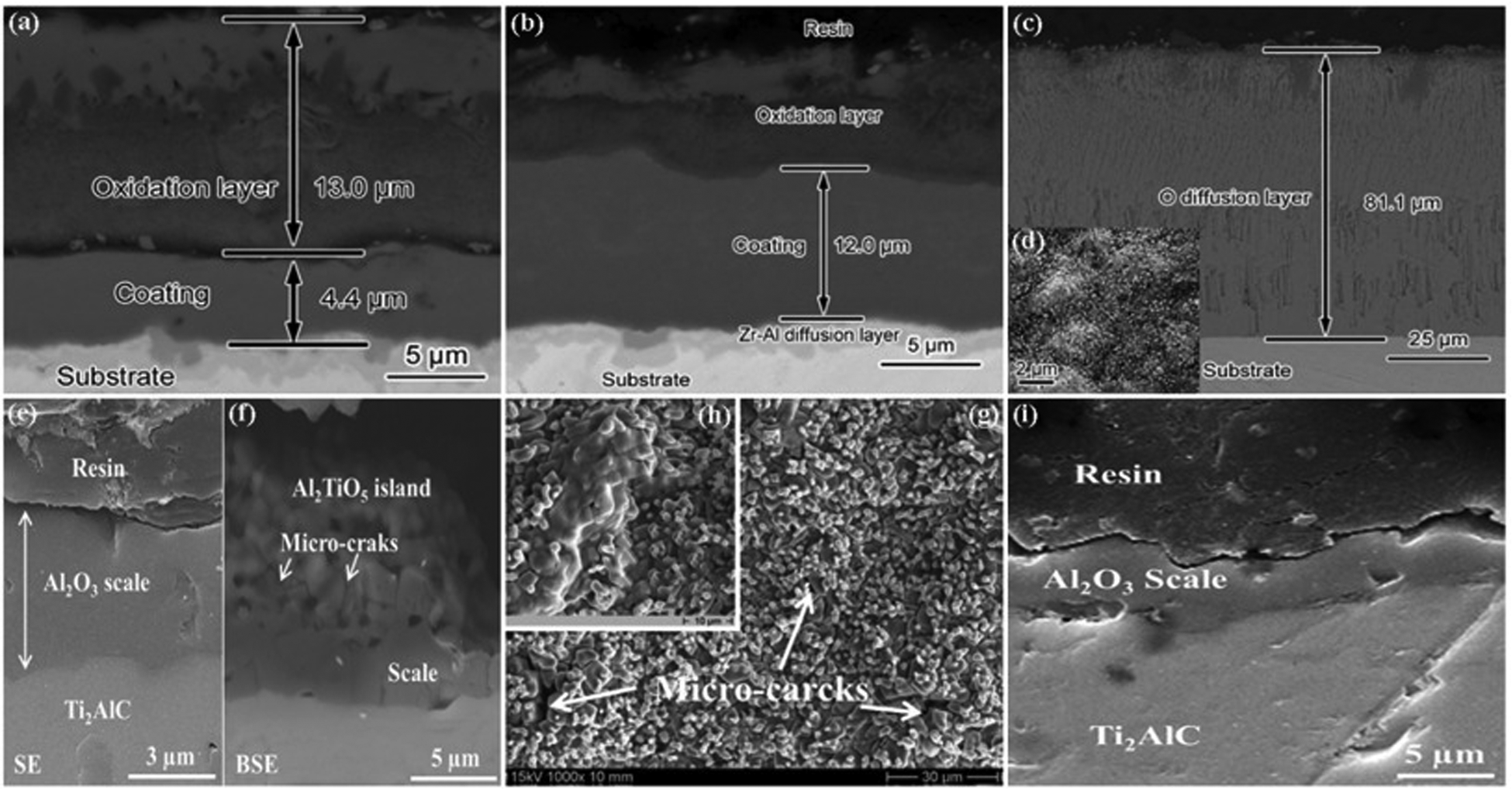
Microscopic images of Ti2AlC-coated zirconium alloy after oxidation under different conditions: (a) 1100 °C/10 min; (b) 1200 °C/5 min; (c) 1200 °C/10 min; (d) high magnification image of (c); (e, f) 1400 °C for 1 h; (g–i) 1500 °C for 1 h; (h) high magnification image of (g). (a–i) Reproduced with permission,24,43 respectively. Copyright 2021 Elsevier B.V. and 2022 Taylor and Francis Ltd.
Other coatings
Li et al. 44 reported the oxidation of Cr67.3Al32.7- and Al-coated Zr-4 alloys. Figures 15(a) and (b) show that many cracks occur on the surface of the aluminium coating after 1 h oxidation at 960 °C. The Al coating is mainly composed of Al2O3, Al0.1Zr0.9O1.95 and ZrO2, as shown in Figure 16(a). Figure 15 shows that ZrO2 is generated due to a large amount of oxidation in the zirconium matrix, and Al coating cannot effectively prevent oxygen from entering the zirconium matrix. Figure 16(b) shows that after oxidation at 960 °C for 1 h, the Cr67.3Al32.7 coating is mainly composed of Cr2O3, Al2O3 and Al3Cr7. Figures 15(c) and (d) show that the surface of the coating is relatively dense, and there are bumps and micro-cracks form on the surface. Zeng et al. 45 reported the properties of Cr0.9Al0.1-coated zirconium alloy. Figures 15(e) to (g) show that the oxidised Cr0.9Al0.1 coating is smooth, free of micro-cracks and bubbles, and has a typical three-layer structure with a thickness of 15 μm. In contrast, the surface of the uncoated Zr-4 alloy forms a ZrO2 layer about 200 mm thick. This shows that the oxidation resistance of Cr0.9Al0.1 coating is very good and can inhibit the internal diffusion of oxygen. Figures 15(g) and (h) show that the outermost layer is mostly dense Cr2O3, the middle layer is a large amount of Cr2O3 and a small amount of dark grey Al2O3 and an unoxidised Cr0.9Al0.1 coating is also observed near the Zr-4 alloy matrix. Therefore, Al coating has no oxidation resistance at 960 °C, Cr67.3Al32.7 coating has good oxidation resistance at 960 °C, and Cr0.9Al0.1 coating has the best oxidation resistance, which can protect zirconium alloy from high-temperature oxidation at 1200 °C.
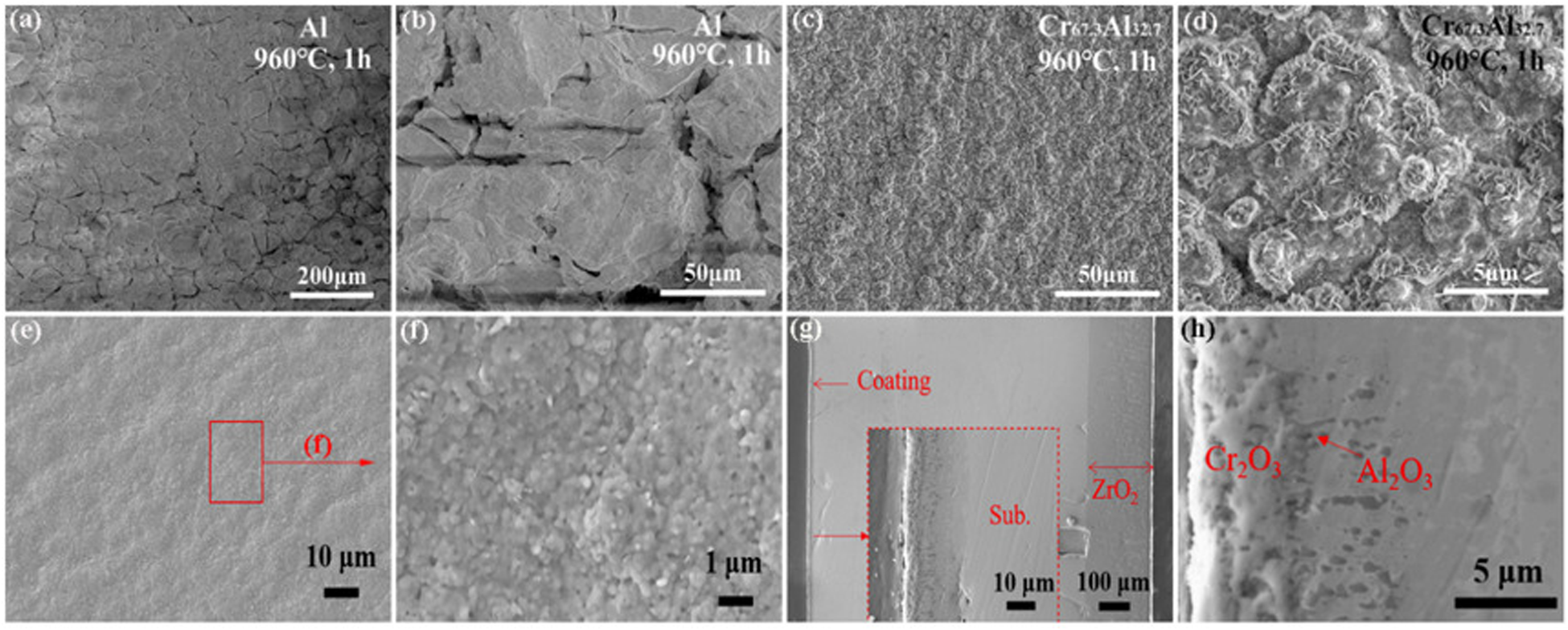
The surface morphology of oxidation-resistant coatings on zirconium alloy after oxidation in high-temperature air at 960 °C for 1 h: (a, b) Al coating; (c, d) Cr67.3Al32.7 coating. Microstructure of Cr0.9Al0.1-coated zirconium alloy after oxidation in 1200 °C steam for 1 h: (e, f) surface morphology; (g, h) section morphology. (a–h) Reproduced with permission,44,45 respectively. Copyright 2021 Elsevier Ltd and 2022 Elsevier Ltd.
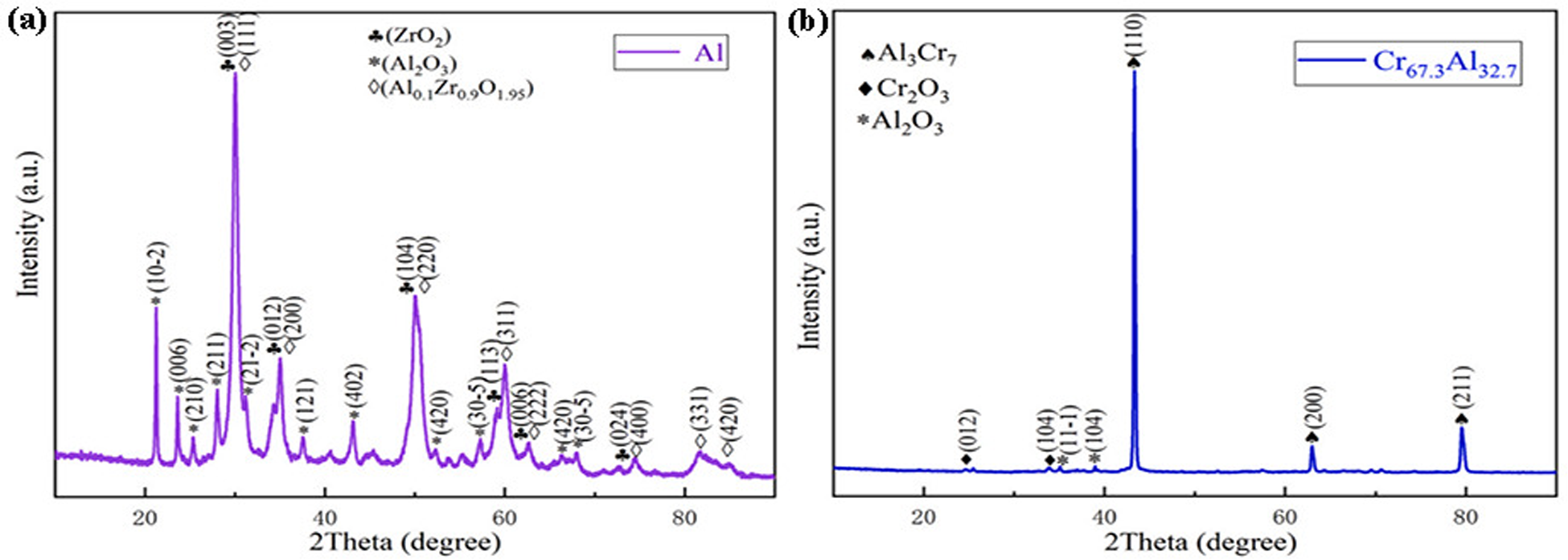
X-ray diffraction (XRD) patterns of Al coating (a) and Cr67.3Al32.7 coating (b) of Zr-4 alloy oxidised in air at 960 °C for 1 h. Reproduced with permission from Li et al. 44 Copyright 2021 Elsevier Ltd.
Dong et al. 46 deposited a Cr62.8Al27.9Si9.3 coating on Zr alloy and discussed its oxidation resistance in high-temperature steam at 1000 °C and 1200 °C. Figure 17(a) shows the XRD patterns of Cr62.8Al27.9Si9.3-coated zirconium alloy after oxidation with different conditions. The original coating is composed of Cr, Al, AlCr2 and Zr. Figure 17(b) shows that the coating surface mainly consists of Cr2O3, α-Al2O3, and a trace amount of Cr after oxidation at 1000 °C for 15 min. After oxidation at 1200 °C for 30 min, a small amount of ZrO2 is also observed (see Figure 17(c)), indicating that oxygen atoms have diffused into the substrate and led to the oxidation of zirconium alloy. Han et al. 47 studied the Zr-4 alloy with FeCrAl–Mo coating. Figure 18(a) shows a dense and uniform Al2O3 layer forms on the surface after oxidation, Mo reacts with Fe to form an intermetallic compound layer, and no diffusion layer is observed between Mo and Zr substrate. Figure 18(b) shows that after oxidising at 1100 °C for 1 h, the Al2O3 layer becomes significantly thicker and non-uniform. The diffusion between Mo and FeCrAl accelerates, and the thickness of intermetallics also increases significantly. There is obvious diffusion between Mo and Zr substrates. Figure 18(c) shows that after oxidation, a very thick layer of alumina forms, effectively filling the internal cavity. There is obvious diffusion between Mo and Zr substrates. Therefore, Al coating does not have good oxidation resistance in high-temperature environments. The Cr67.3Al32.7 coating, Cr0.9Al0.1 coating, Cr62.8Al27.9Si9.3 coating and FeCrAl–Mo coating all have good oxidation resistance, and FeCrAl–Mo coating has the best oxidation resistance.
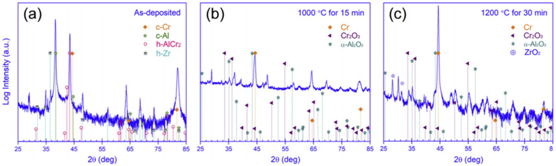
X-ray diffraction (XRD) patterns of Cr62.8Al27.9Si9.3-coated zirconium alloy after oxidation: (a) as deposited; (b) 1000 °C/15 min; (c) 1200 °C/30 min. Reproduced with permission from Dong et al. 46 Copyright 2018 Elsevier Ltd.
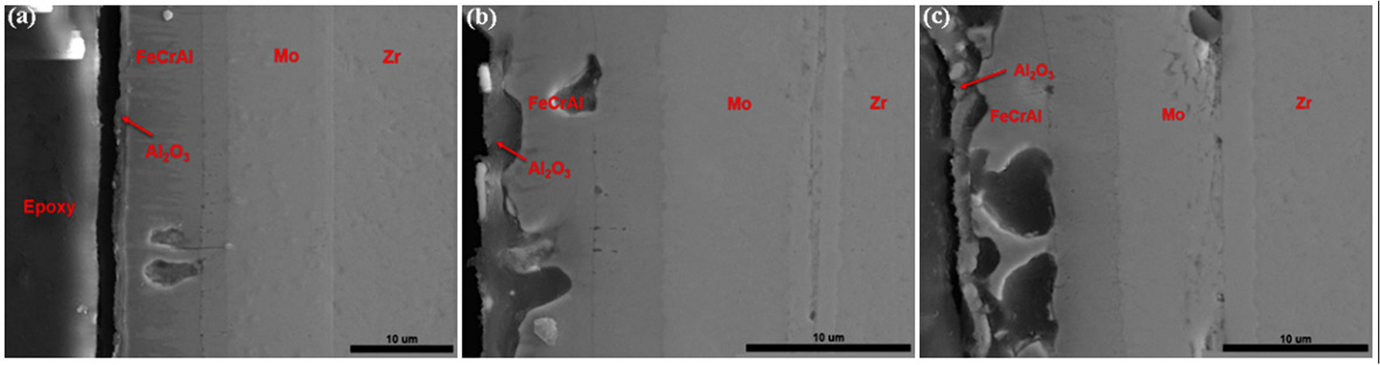
Scanning electron microscopy (SEM) images of feral-mo-coated zirconium alloy after oxidation for 1 h under different conditions: (a) 1000 °C, (b) 1100 °C and (c) 1200 °C. Reproduced with permission from Han et al. 47 Copyright 2019 Elsevier Ltd.
Oxidation behavior and failure mechanism of coatings
Figure 19 shows the oxidation failure mechanism of chromium-plated Zr-4 alloy in transient steam. Figures 19(a) and (b) show that the α-Zr phase gradually transforms into the β-Zr phase after oxidation in high-temperature steam at 1300 °C, Cr diffusion into zirconium substrate, and dissolved in Zr-4 substrate β-Zr medium. When the temperature rises to 1350 °C, Cr stops diffusing into the zirconium matrix, and a thicker Cr–Zr phase forms between the α-Zr(O) layer and the β-Zr matrix, as shown in Figure 19(c). When the temperature rises to 1400 °C, oxygen begins to diffuse into the β-Zr substrate, and β-Zr gradually transforms into α-Zr(O). Zr–Cr will undergo a eutectic reaction, and Cr2O3 will also volatilise. Finally, the Cr coating gradually failed, and oxygen passed through the chromium coating, causing oxidation of the zirconium substrate. However, the dense columnar ZrO2 layer reduces the corrosion rate to a certain extent, thus inhibiting the generation of hydrogen (see Figure 19(d)). As shown in Figure 19(e), when the temperature rises to 1500 °C, the zirconium substrate suffers a severe oxidation, and the T-ZrO2-x is gradually transformed into C-ZrO2-y. The formation of ZrO2 accelerates corrosion and hydrogen production. Figure 19(f) shows that when the temperature rises to 1550 °C, the remaining Cr, Fe and Sn gradually diffuse into the matrix and are then consumed by oxidation.
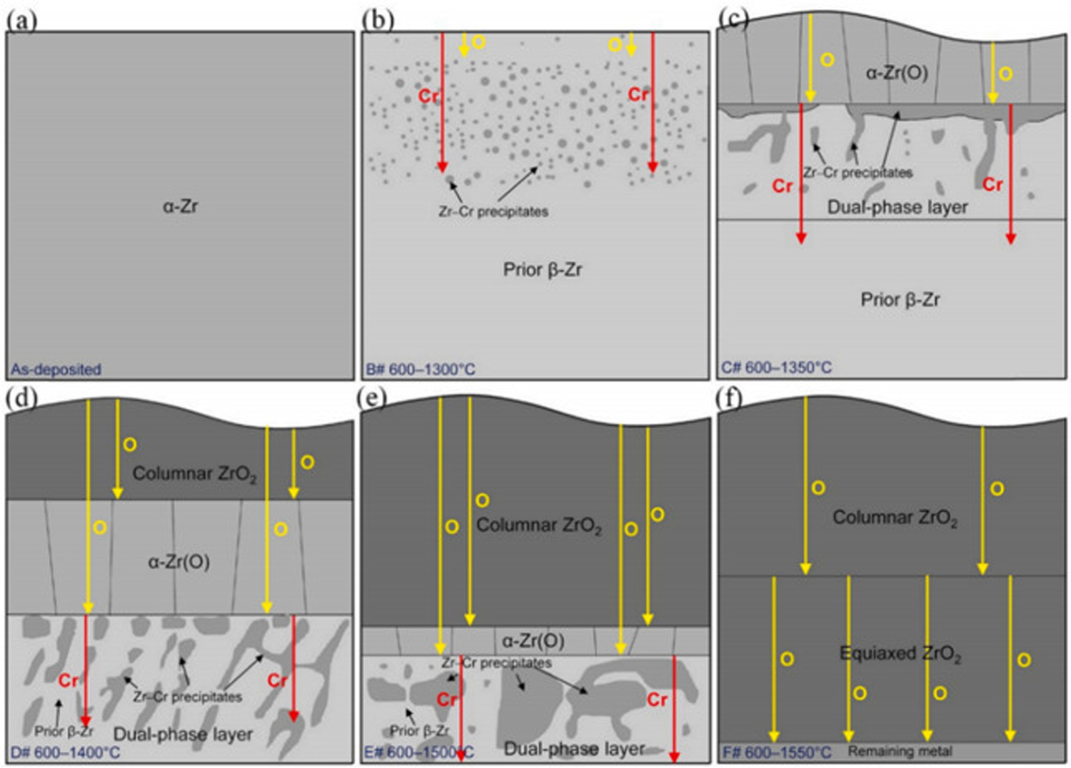
Failure mechanism diagram of oxidation of chrome-coated zirconium alloy. Reproduced with permission from Liu et al. 1 Copyright 2021 Elsevier Ltd.
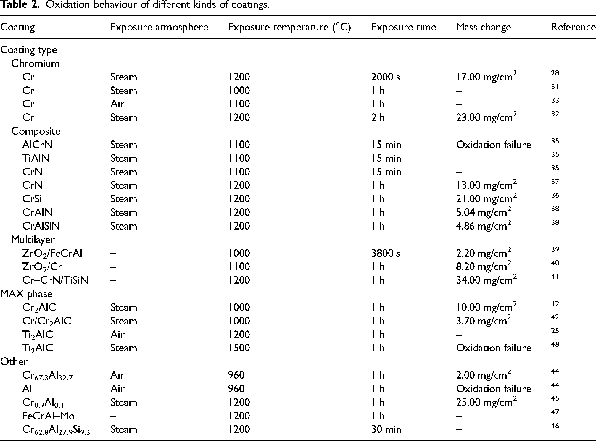
Figure 20 shows the oxidation failure mechanism of Ti2AlC-coated zirconium alloy in 1400 °C steam. At the initial stage of oxidation, a thin oxide layer forms. During the oxidation process, a titanium-rich island (Al2TiO5) forms on the surface, and some small alumina nucleation also forms in the middle layer. With the progress of oxidation, the volatile titanium oxide forms a continuous α-Al2O3 layer, and the nucleation cavity forms at the interface. Finally, due to stress relaxation α-Al2O3 layer breaks, delamination and cracks, resulting in α-Al2O3 layer failure. Table 2 summarises the oxidation behaviour of different kinds of coatings studied in this paper.
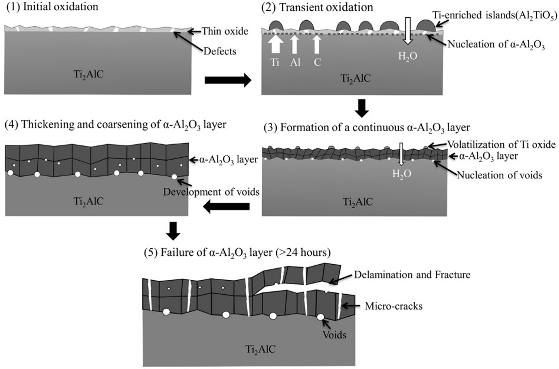
Oxidation failure mechanism of Ti2AlC-coated zirconium alloy in 1400 °C steam. Reproduced with permission from Tang et al. 48 Copyright 2017 Elsevier Ltd.
Oxidation behaviour of different kinds of coatings.
Conclusion and prospects
In this paper, the oxidation behaviour of various coated zirconium alloys under different conditions was reviewed, and the microstructure, oxidation kinetics and failure mechanism of oxidation protection were studied and analysed. The results show that the chromium coating, composite coating, multilayer coating and MAX phase coating have good properties. During the reaction, oxygen accelerates the oxidation rate of the zirconium matrix through micro-cracks, pores and voids on the surface of the coating. During the oxidation process of chromium-plated zirconium alloy, a protective Cr2O3 oxide film will form on the substrate surface. Forming Cr2Zr between Cr–Zr layers can enhance the adhesion between chromium coating and matrix, and has good oxidation resistance. The composite coating mainly consists of Cr, Al, Si, N and other elements. The oxidation coating is mainly an oxide of Cr2O3 and Al, Si, N and other elements. Chromium composite coating can protect the zirconium alloy matrix from oxidation corrosion to some extent. The multilayer coating and MAX phase coating prepared on the surface of zirconium base alloy have two-layer structures and three-layer structures, respectively. After oxidation at 1100 °C, the oxygen diffusion channel on the surface of the substrate is small, and the oxide layer has good adhesion with the substrate, which can protect the zirconium substrate from high-temperature oxidation. When the temperature increases, the oxygen diffusion channel on the substrate surface becomes larger and the oxide attachment becomes weaker, but it can still block the internal diffusion of oxygen. Therefore, the combination of Cr coating and multilayer coating or MAX phase coating will be a promising surface coating protection technology. It not only generates a highly protective Cr2O3 oxide film, but also makes the coating and the substrate more compact. The multilayer structure can prevent oxygen from diffusing inward, which makes the oxidation resistance of zirconium alloy stronger.
Footnotes
Author contributions
The manuscript was written through the contributions of all authors. Y.Y. Zhang: Conceptualisation, investigation, validation and supervision. Y.Y. Zhang and L.Y. Chen: Writing original draft and image processing. Y.Y. Zhang, L.Y. Chen and H.W. Wang: Resources, investigation, and writing – review and editing. S.N. Li and T. Fu: Visualisation and writing – review and editing. All authors have given approval to the final version of the manuscript.
Declaration of conflicting interests
The authors declared no potential conflicts of interest with respect to the research, authorship, and/or publication of this article.
Funding
The authors disclosed receipt of the following financial support for the research, authorship, and/or publication of this article: This work was supported by the Distinguished Youth Fund project of the Anhui Provincial Education Department (No. 2023AH020019) and the Excellent Youth Fund project of the Anhui Provincial Department of Science and Technology (No. 2108085Y19).