
Abstract
The fretting wear properties of a nanocrystalline layer with laser shock peening (LSP) on the surface of Ti–6Al–4V (TC4) alloy were investigated to improve the fretting friction performance at 25 °C and 500 °C. The fretting operation characteristics and material damage mechanism of the LSP–TC4 alloy were investigated through a friction dissipation model and two kinds of operation fretting models. The contact morphology and three-body behaviour on the surface were also revealed. The wear resistance performances of the strengthened surfaces exceeded those of unreinforced surfaces at 25 °C and 500 °C but the LSP-treated alloy was more stable at 25 °C. As revealed in the operation fretting models, the fretting running region of the LSP layer consisted of a mixed slip regime and gross slip regime. The material response area was composed of slight and abrasive wear areas at 500 °C. The improved fretting fatigue resistance of TC4 alloy was attributed to the refined internal organisation and high-density dislocation organisation of LSP, which inhibits the initiation and propagation of fatigue cracks.
Introduction
Characterised by concealment and complexity, fretting wear phenomena commonly occur in aerospace, marine equipment, chemical equipment and nuclear energy facilities.1,2 Fretting wear easily causes contact surface loosening, which reduces the accuracy and reliability of fitting; moreover, contamination with solid abrasives promotes early failure of the mechanism. 3 As the blade material in aircraft engines, Ti–6Al–4V (TC4), TC6, TC11 and TC17 titanium alloys are favoured for their low density, high strength-to-weight ratio, low modulus of elasticity and high corrosion resistance.4–6 TC4 alloy is an α + β dual-phase titanium alloy (where the α phase has a spherical hexagonal close-packed structure and the β phase has a strip body centred cubic structure). However, TC4 alloy has poor tribological properties and its work-hardening ability is sensitive to fretting wear. Within the complex and precise structure of an aero-engine, TC4 alloy is also prone to fretting damage.7,8 During their service, the blades (which are the key components of an aircraft engine) are subjected to multi-scale couplings of centrifugal force, high temperature, gas excitation and vibration, which increase the risk of various types of failures. The most prominent problems are periodic separation and contact between the blade root and the contacting rim surface caused by rotor vibrations and severe fretting wear of the blade root caused by small amplitudes and alternating stresses on the contacting surface. 9
To improve the surface properties of TC4 alloy, many researchers have developed surface modification methods. The dominant methods are surface coating treatment, micro-arc oxidation, and laser shock peening (LSP).10–13 LSP exerts a minimal thermal effect on the matrix metal but is more practical and controllable than other methods. Crack suppression in aircraft engine components is a new direction for the future development of surface-strengthening technology.14–16 Qiao 17 explored the fretting wear properties of titanium alloy treated by laser nitriding and ion nitriding. Both treatments effectively inhibit the wear on titanium alloy, although the wear resistance is more improved by laser nitriding than by ion nitriding because the laser beam promotes bonding between the nitriding bodies and the matrix. Applying the LSP process, Roshith and Jose 18 formed nanocrystalline layers that effectively improve the fretting wear characteristics of a TC4 alloy surface. Altenberger et al. 19 reported a 1.5 mm deep residual stress layer on an LSP-treated TC4 surface and a significantly higher stress value than can be achieved by shot peening. The residual stress on a 0.5 mm deep layer was effectively released in the fretting process. LSP can more effectively inhibit fatigue crack generation and expansion than shot peening. Tabie et al. 20 compared the LSP process at low power density/high impact time with that of large power density/low impact time. When the impact time was extended, the plastic deformation limit of the material surface approximated the saturation limit, enhancing the hardness and fatigue life by 25% and 40%, respectively. Liu et al., 21 who studied the residual stress on LSP-treated TC4 titanium alloy, showed that an alternating load applied at 450 °C–550 °C induces relaxation behaviour in the alloy. Nevertheless, the thermal stability and fatigue resistance are maintained by the high-density dislocation structure in the work-hardening layer. LSP technology has been widely applied to (α + β) dual-phase titanium alloys. Whereas many studies have reported the residual stress and fatigue properties of LSP-treated titanium alloys, the characteristics and mechanism of fretting wear remain under investigated.
LSP has been widely adopted in studies of fretting wear characteristics owing to its unique technical advantages. The present study explores the friction and wear properties of LSP-treated α+β TC4 alloy (LSP–TC4) under different fretting amplitudes at 25 °C and 500 °C. By analysing the residual stress layer and fretting wear characteristics of the TC4 alloy before and after LSP treatment, the resistance to fretting damage and surface integrity of the alloy are revealed. The study also provides theoretical support and a practical reference for the design of alloys with fretting wear resistance.
Materials and methods
Specimen preparation
The test substrate materials were TC4 alloy sheets. Figure 1(a) is a scanning electron microscopy (SEM) image of the alloy morphology. Specimens sized φ 24 mm × 8 mm were cut from the sheets and their surfaces were polished first with metallographic water abrasive paper of different mesh sizes and then with SiO2 polishing solution (particle size = 0.04 µm) to obtain a mirror surface (surface roughness Ra = 0.03–0.04 µm). The surfaces of the TC4 alloys were then strengthened by LSP using an Nd–YAG solid-state laser (see Figure 1(b)), forming a 1 mm thick residual stress layer with fine grains and work hardening. During the LSP operation, the laser output power was set to 3 W (power density = 4.71 GW) and the lap rate was 50% (Figure 1(c)). The surface of the TC4 alloy presented many micro-pits and formed a nanocrystal layer (see the SEM image in Figure 1(d)).
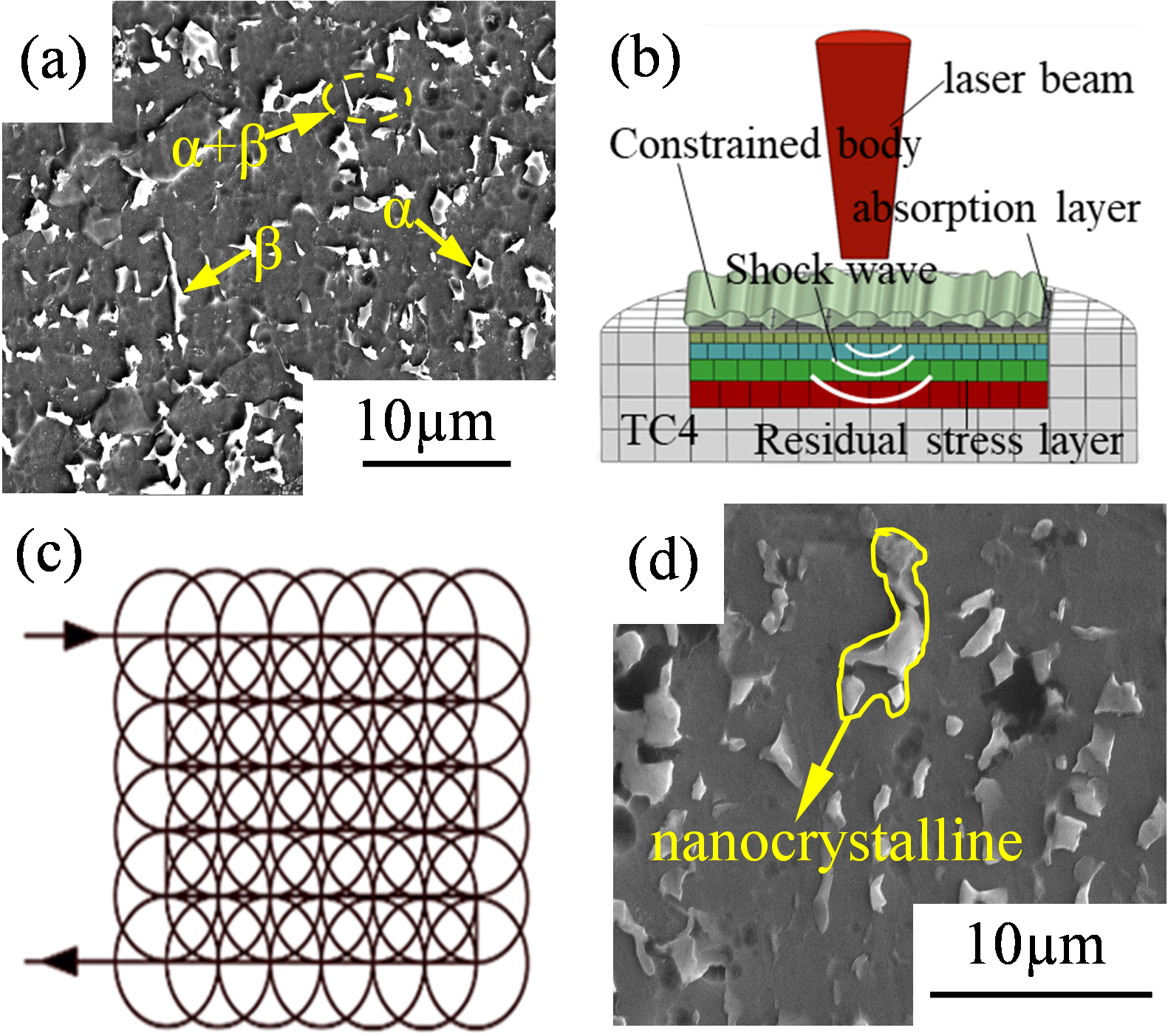
Schematic diagram of laser shock peening (LSP) and specimen surface morphology.
Fretting experiment
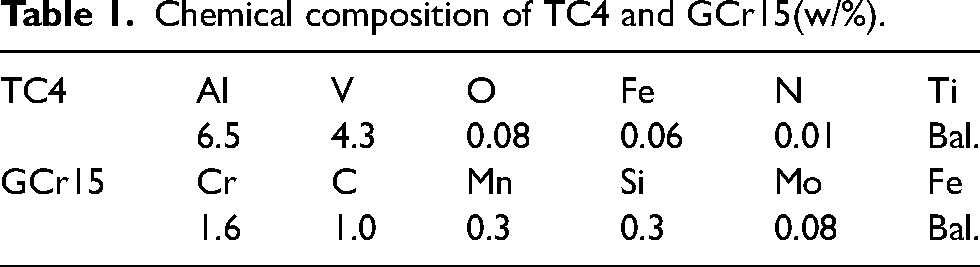
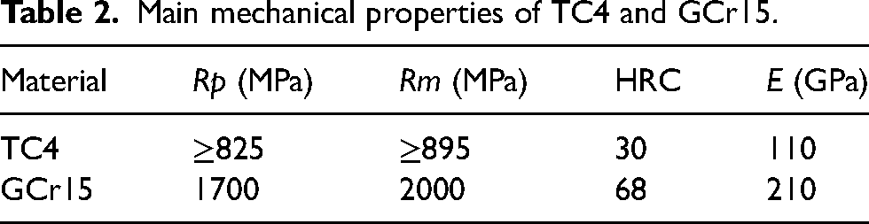
The TC4 and LSP–TC4 alloys were subjected to friction experiments on a fretting friction and wear testing machine (SRV-IV, Optimol Corporation, Germany) operated in tangential fretting mode, as shown in Figure 2. The upper sample was a GCr15 steel ball with a diameter of 10 mm (Ra ≤ 0.02 µm, Vickers hardness HV ≈ 6800 MPa). The lower sample was the TC4 specimen (Ra ≤ 0.04 µm, HV ≈ 3000 MPa) or the laser-shocked LSP–TC4 sample. The chemical compositions and main mechanical properties of the samples are shown in Tables 1 and 2.
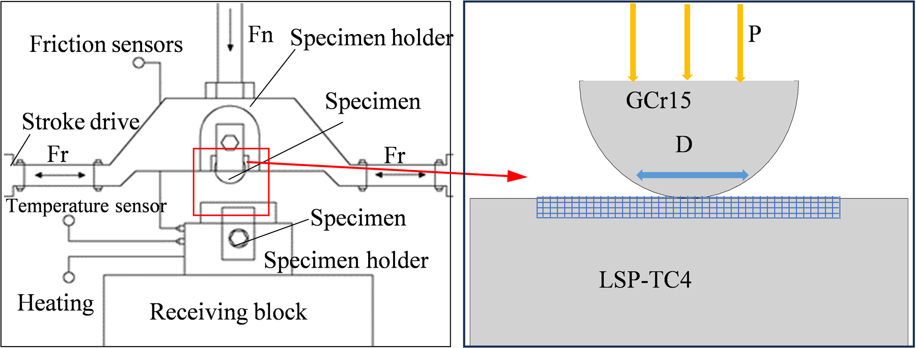
Schematic diagram of fretting wear testing machine and fretting wear operation schematic diagram.
Chemical composition of TC4 and GCr15(w/%).
Main mechanical properties of TC4 and GCr15.
The working temperature of the titanium alloy used in the aero-engine was maintained at 450 °C–600 °C.22,23 The fretting wear experiment was carried out at 25 °C and 500 °C. Prior to the experiment, the sample was slowly heated to 500 °C and then kept warm for 10 min. The experiment was started after the temperature field had stabilised. The normal load was 50 N, the displacement amplitudes were 50, 100, and 150 µm, the contact frequency was 25 Hz, and the fretting wear time was 1800 s. Before starting the experiment, the surface was wiped with an anhydrous alcohol cotton ball and the attached particles were removed. After the test, the sample was placed in acetone solution and ultrasonically cleaned and dried. The microstructure of the fretting area, wear volume, friction contact area, elemental composition and wear contour curves were obtained using SEM, laser confocal scanning microscopy, and energy dispersive X-ray spectroscopy (EDS).
Results and discussion
Friction coefficient
The friction coefficient dictates the wear characteristics of the contact surface at any time, along with the contact and damage states of the micro-convex bodies at the instantaneous friction interface. 24 Figure 3 shows the temporal variations in the friction coefficient of TC4 alloy under different displacement amplitudes at 25 °C and 500 °C. The friction coefficient is roughly divisible into three stages. In the initial stage, the friction coefficient is low because the material surface is covered with a very thin oxide film and small particles that protect the surface and reduce the friction. During the fluctuation stage, the surface oxide layer is disrupted, aggravating two-body action under shear stress and extrusion deformation. The staggered distribution of micro-convex bodies alters the periodic local stress changes, causing fluctuations in the friction coefficient. In the stable stage, the oxyphilic ability of the abrasive grains is enhanced by high temperature and friction heat. The enhanced function of the three-body system reduces the friction coefficient and fluctuation degree.
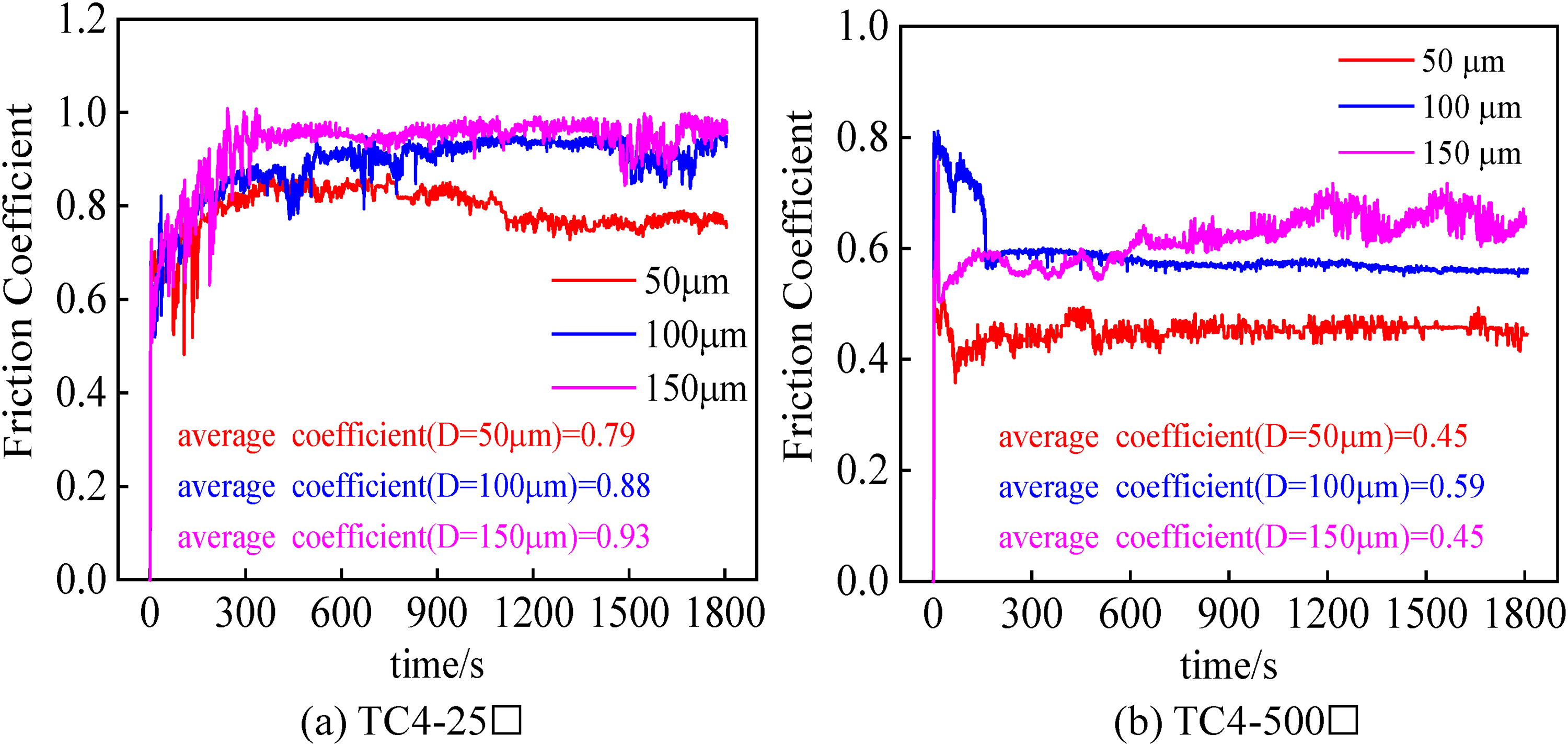
Friction coefficient curves of TC4 alloy at different temperatures under displacement amplitudes: (a) TC4-25 °C and (b) TC4-500 °C.
Figure 4 shows the friction force (Ft)–displacement amplitude (D)–cycle times (N) curves of LSP–TC4 alloy at 25 °C and 500 °C. From the evolution characteristics of the Ft–D–N curves, we can identify three regimes of the contact area: the gross slip regime (GSR), mixed slip regime (MSR), and partial slip regime (PSR). At 25 °C, the fretting operating region changes from PSR to MSR and finally to GSR (Figure 4(a)–(c)), but at 500 °C, it changes from linear PSR to elliptical MSR under a displacement of 50 µm, where the adhesive zone begins to change from elastic to plastic coordination (Figure 4(d)). When the displacement increases from 50 to 100 µm, the contact area tends to form the third body due to the reduction of the adhesion zone, which is regulated by the MSR (Figure 4(e)). When the displacement increases to 150 µm, the contact is dominated by the GSR (Figure 4(f)) and the friction heat and high temperature of the friction process accelerate the generation of the oxide layer and diffusion along the thickness direction, thus weakening the direct contact. According to these results, the contact area is sensitive to adhesion and the oxide layer formed by the compacted abrasive chips acts as a solid lubricant. As shown in Figure 5, the friction coefficient of LSP–TC4/GCr15 is lower and has less fluctuation in the high-temperature environment than at 25 °C. The average friction coefficients of the TC4 alloy and LSP–TC4 alloys were determined under different displacement amplitudes at 25 °C and 500 °C. The average friction coefficients of the LSP–TC4/GCr15 and TC4/GCr15 pair exhibit the same trend with displacement amplitude. The friction coefficient is large on the unenhanced surface, which lacks residual stress protection at 25 °C. The residual stress of the nanocrystal layer relaxes at 450 °C–650 °C, reducing its protective effect on TC4 alloy. For this reason, the LSP–TC4 alloy shows a slightly higher friction coefficient than TC4 alloy at 500 °C. Stress relaxation largely influences the high-temperature wear resistance of TC4 alloy.
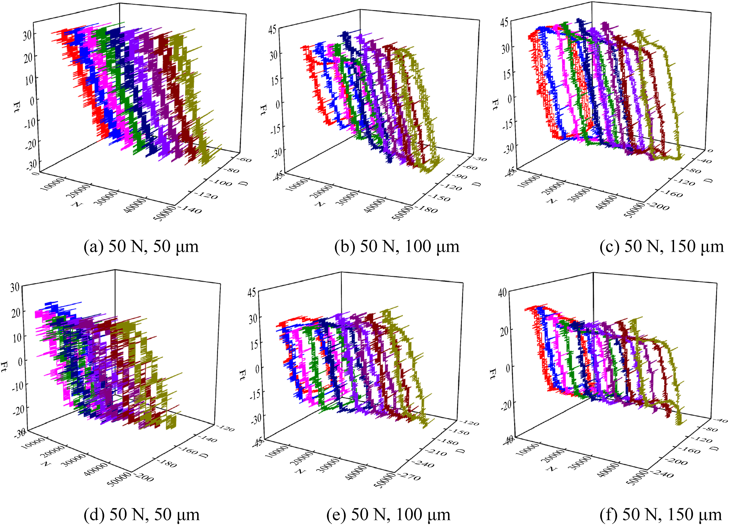
Ft–D–N curves of LSP–TC4 alloy under different displacement amplitudes (a–c: 25 °C; d–f: 500 °C): (a) 50 N, 50 μm; (b) 50 N, 100 μm; (c) 50 N, 150 μm; (d) 50 N, 50 μm; (e) 50 N, 100 μm; and (f) 50 N, 150 μm.
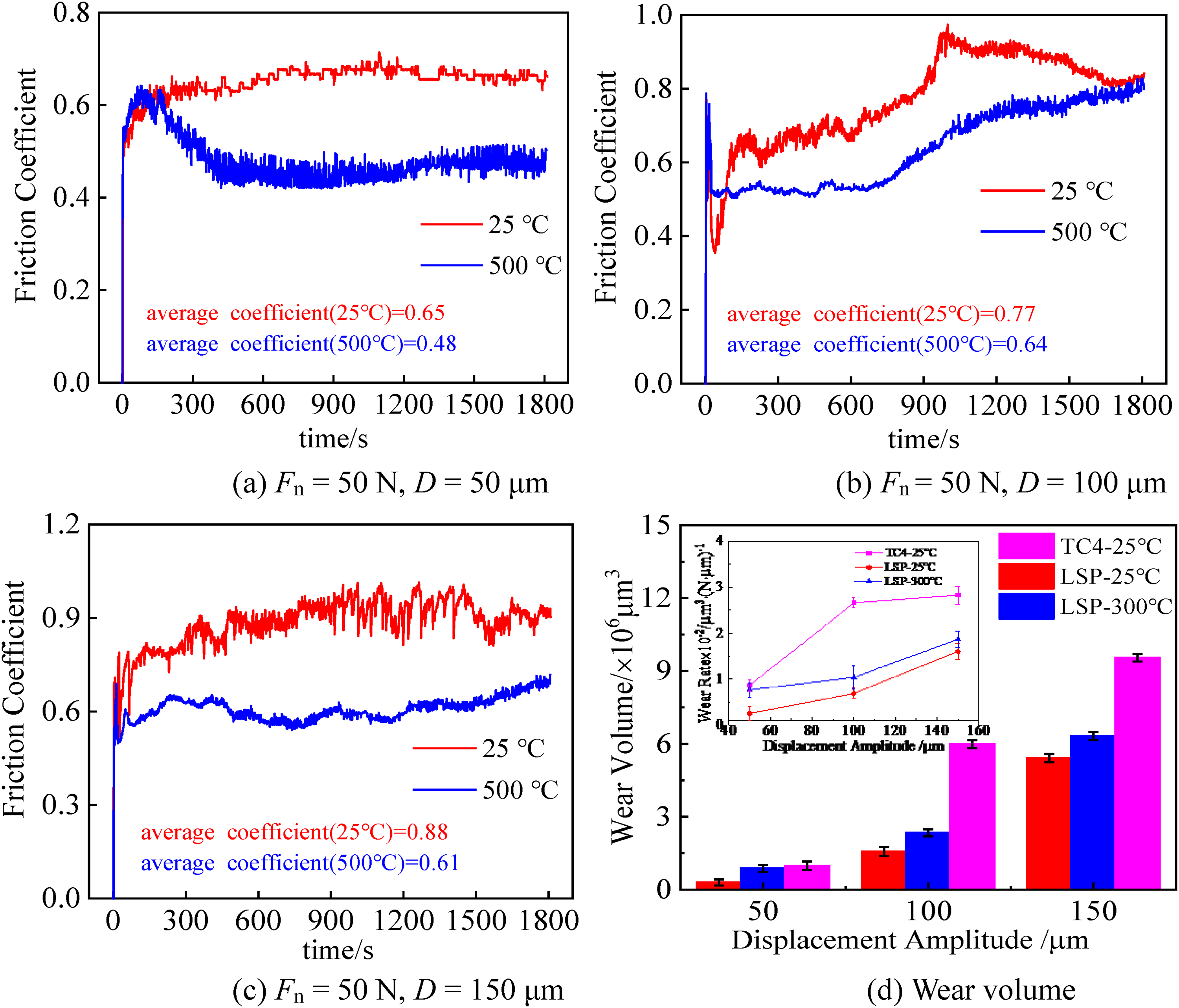
Variation curves of friction coefficient and average friction coefficient of LSP–TC4 alloy at different displacement amplitudes at 25 °C and 500 °C with time: (a) Fn = 50 N, D = 50 μm; (b) Fn = 50 N, D = 100 μm; (c) Fn = 50 N, D = 150 μm; and (d) wear volume.
The wear volume and wear rate reflect the wear characteristics of the TC4 and LSP–TC4 alloys. The wear volume was measured using an OLYMPUS OLS5000 3D laser confocal microscope and the wear rate was calculated as
Analysis of the wear characteristics
Figure 6 shows the two-dimensional profiles and macro characteristics of the fretting wear spot on the LSP–TC4/GCr15 pairs at 25 °C and 500 °C. At D = 50 μm, only slight wear marks appeared at the edge of the adhesive-wear spot. As the displacement increased from 50 to 150 µm, the abrasive-wear spot developed a ‘W’ shape due to oxidative compaction of the abrasive particles. Meanwhile, the surface roughness was much smaller at 25 °C than at 500 °C (see Figure 6(d)). At high temperatures, the hard abrasive particles formed by the broken third body ploughed the metal matrix, causing secondary injuries. The wear patterns of the LSP–TC4 alloy at high temperatures were mainly driven by the oxidation layer protection, abrasive debris action and residual stress release (Figure 6(h)).
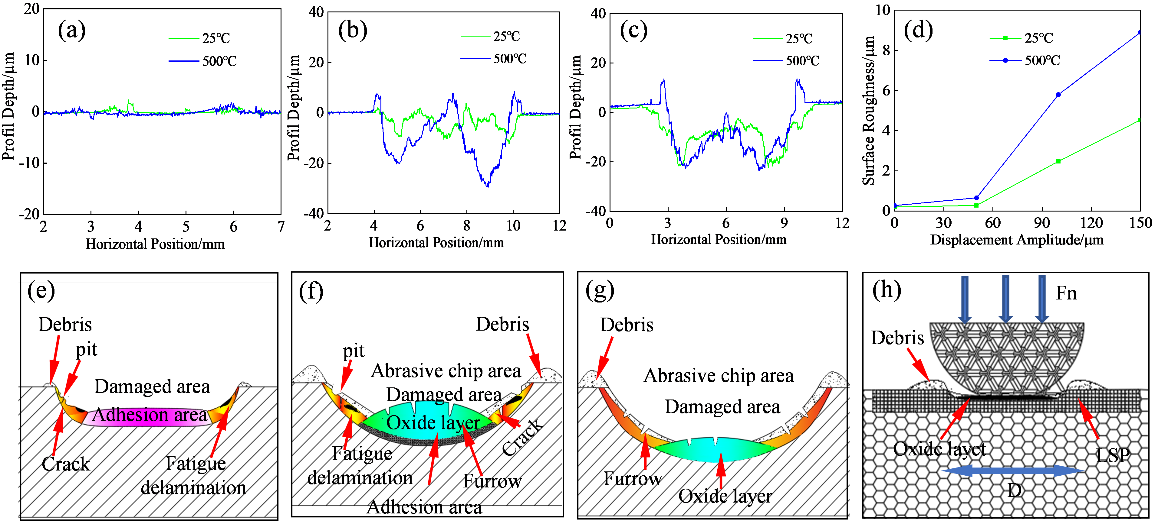
Two-dimensional contours and surface roughness profiles of the contact area of LSP–TC4 alloy under different displacement amplitudes at 25 °C and 500 °C: (a), (e) 50 N, 50 μm; (b), (f) 50 N, 100 μm; (c), (g) 50 N, 150 μm; (d) surface roughness versus displacement amplitude; and (h) wear patterns.
The friction dissipation model
25
improves the Archard model
26
by including the friction problem in wear modelling. The friction dissipation energy is calculated using equation (2). Energy dissipation
27
can be defined in terms of an energy-wear coefficient α, defined as the ratio of V to Ed. Using this parameter, we can compare the fretting wear characteristics of the substrate conversion layer: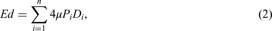

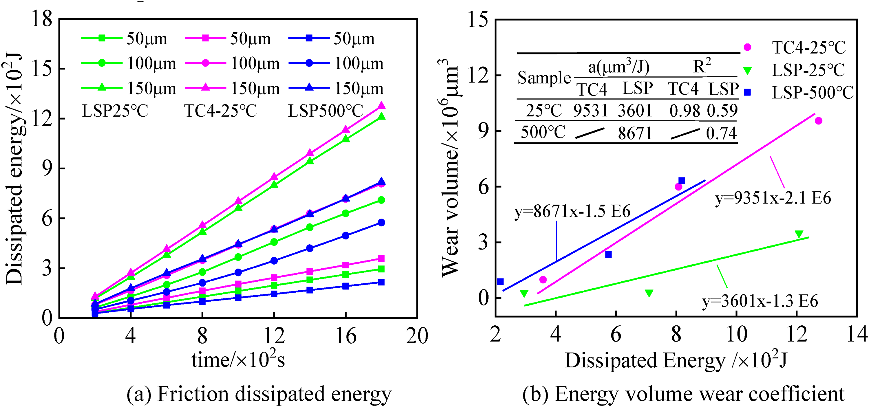
Wear coefficient plots (friction dissipation energy and energy volume versus time plots) of the TC4 and LSP–TC4 alloys under different displacement amplitudes at 25 °C and 500 °C: (a) friction dissipated energy and (b) energy volume wear coefficient.
Grinding scar morphologies
The forms of the fretting wear spots were identified from three-dimensional morphological models and SEM images of the LSP–TC4 alloy captured at 25 °C and 500 °C. Under D = 50 μm, the nanocrystal layer presented a sticky fretting form with slightly slippery edges (Figure 8, the first column). The wear traces in the centre of the contact area were slighter than the fretting wear spots at 25 °C, and the adhesion–slip boundary region sustained most of the fretting damage during fatigue wear and delamination, reflecting the moderating effect of the PSR. At D = 100 μm, the fretting wear spots appeared as discontinuous third bodies with a poor protective effect. Again due to the moderating effect of the MSR, ploughing and fatigue cracks developed in the contact area along the fretting direction. Within the fretting wear spot, the oxidation reaction at 500 °C was covered by a black compaction area with high shear resistance and lubrication characteristics (Figure 8, the second column).
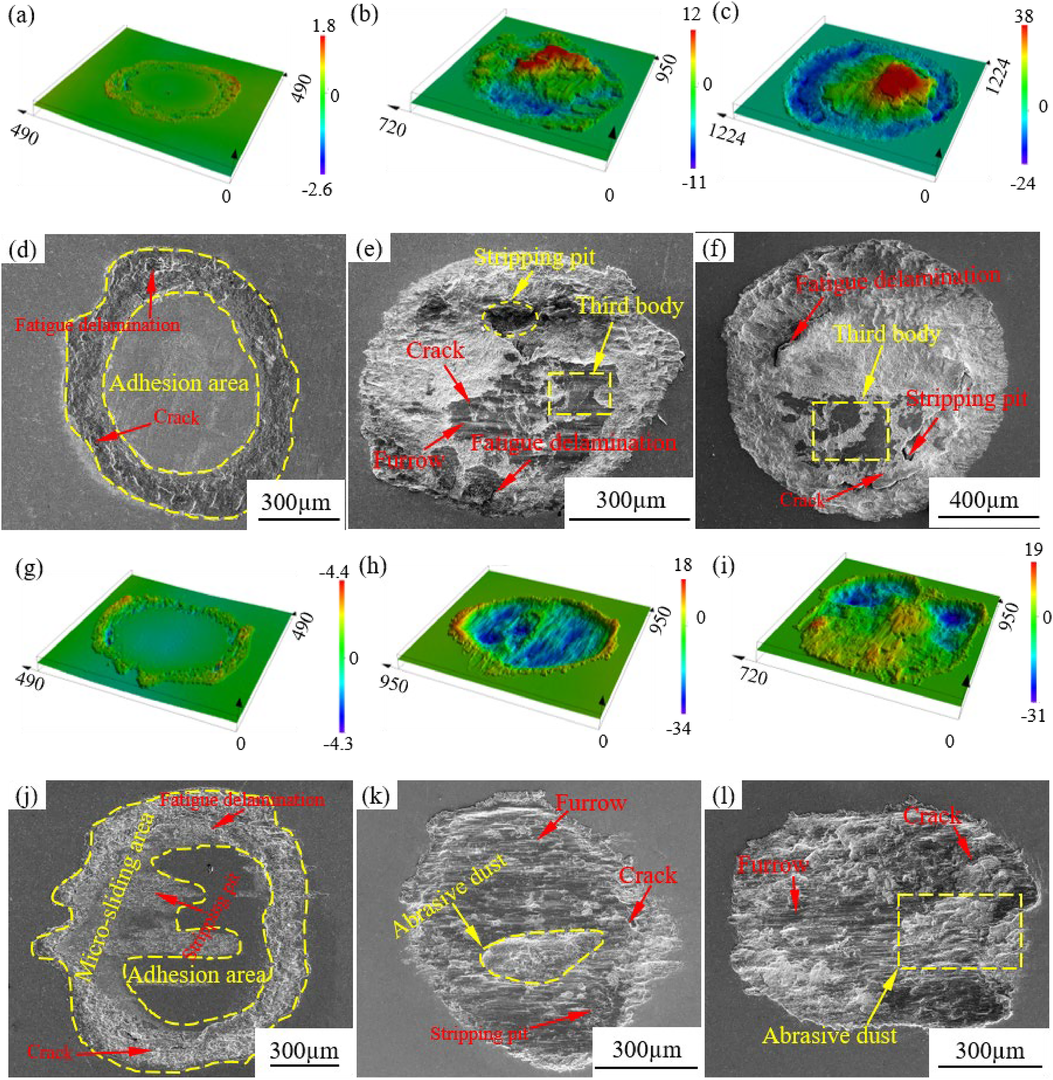
Three-dimensional and scanning electron microscopy (SEM) morphologies of wear scars on LSP–TC4 alloy at different displacement amplitudes at 25 °C (a–f) and 500 °C (g–l).
When the displacement reached 150 µm, the third body layers with the worst continuity appeared in the contact area and the three-body effect was weakened at 25 °C because the growth rate of the third bodies under ploughing is much smaller than the wear rate. At 500 °C, high temperatures increase the oxyphilic ability of metal materials. 28 During the wear process, the wear-oxidation–compaction-wear was dynamically balanced, and a dense oxide layer was generated in situ. Abrasive particles were scattered in the contact area and furrows formed during fretting (Figure 8, the third column).
Wear mechanism
To understand the wear mechanism, the wear contact areas of the TC4 and LSP–TC4 alloys during gross slip operations at 25 °C and 500 °C were observed in SEM images (Figure 9). Panels (a) and (d) of Figure 9 display the PSR contact area of TC4 at 25 °C and 500 °C. At room temperature, micro-convexity in the contact area formed spalling pits during the adhesion fracture process, whereas at high temperature, slight wear marks developed on the TC4 surface. Under the action of high temperature and frictional heat, abrasive particles were formed by adhesion and fracture and small oxide particles were sintered into a friction oxide layer under normal load. With its high hardness and good shear resistance, the oxide layer improved the wear resistance of the base metal. Panels (g) and (j) of Figure 9 are SEM images of the LSP–TC4 alloy at 25 °C and 500 °C, respectively. At room temperature, the contact area of the sample was slightly indented under a normal load and slight wear marks formed during the fretting process. During high-temperature fretting, the oxide layer was lost and the contact centre showed slight ploughing marks caused by sliding of the oxide particles. Many peeling pits and small fatigue-detachment layers also appeared, resulting in stress relaxation and an LSP micro-texture at the surface. Consequently, the fretting wear originally occurring in the PSR occurred in the PSR-to-MSR transition area.
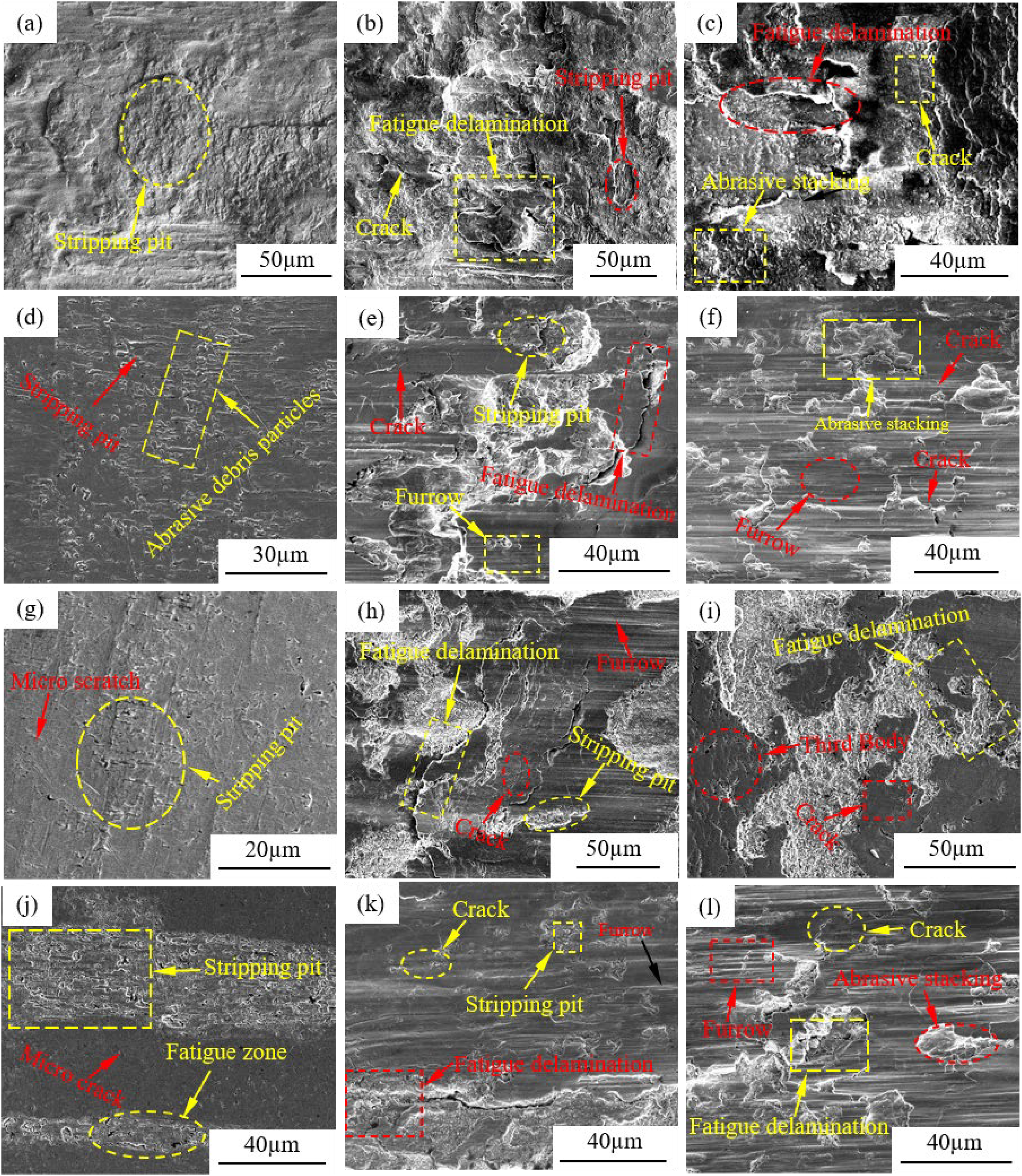
Scanning electron microscopy (SEM) micrographs showing the wear scars of TC4 and LSP–TC4 alloys under full sliding mode at 25 °C and 500 °C.
Panels (b) and (e) of Figure 9 show the micro-morphologies in the MSR contact area of TC4 at 25 °C and 500 °C, respectively. The matrix-metal grinding surface shows a complex morphology and the friction heat formed during the cycle was insufficient to oxidise the abrasive particles and hence form a continuous third body. The surface morphology was mainly formed by adhesive tearing, fatigue shedding of the oxide layer and micro-cracks, indicating two-body wear dominated by elastic deformation, plastic deformation and crack regulation. At 500 °C, the contact areas of the TC4 and LSP–TC4 alloys were covered with an oxidation layer sintered at high temperatures. The wear was characterised by oxidation, fatigue, spalling and crack initiation and propagation. The LSP–TC4 alloy presented an improved surface hardness and fine grains (Figure 9(h) and (k)). Fine spalling particles were oxidised and compacted under the action of frictional heat, forming a black laminar compacting layer with poor continuity. Abrasive particles were continuously ploughed and compacted to form furrows along the fretting direction. Fatigue shedding and micro-cracks formed in the contact area.
The right panels of Figure 9 display the SEM morphologies in the GSR. The TC4 alloy showed severe plastic deformation in the contact area and lamellar shedding caused by continuous fretting wear. The contact surface was severely worn (Figure 9(c) and (i)). Meanwhile, the contact area of the LSP–TC4 alloy was covered by a discontinuous oxide layer formed under frictional heat. The grinding surface was smooth and the internal grains were refined. This alloy exhibited obvious work hardening and slight wear. Clear traces of ploughing appeared in the contact area at 500 °C (Figure 9(f) and (l)). The fretting contact surface of each metal formed a third body with good continuity, good shear resistance and high hardness. During the wear process, the third body was wrapped on the surface and the wear mechanism was single. However, abrasive particles were scattered in the contact area and the surface metal was continuously ploughed, intensifying the loss rate of the metal materials.
Analysing the fretting-operation region is essential for elucidating the damage mechanism of a material. For this purpose, the micro-motions on the TC4 and LSP–TC4 alloys were determined from plots of normal load versus displacement amplitude. At 25 °C, the fretting map under the operating condition of the LSP–TC4 alloy was consistent with that of the TC4 alloy and comprised PSR, MSR and GSR. However, the TC4 alloy developed serious wear marks along with dominant cracks and fatigue shedding. In the LSP–TC4 alloy, fatigue was reduced because the LSP process generated surface weaving and a dislocation structure, leading to minor single wear forms. At 500 °C, the LSP–TC4 alloy consisted mainly of MSR and GSR. In the TC4 alloy, almost no wear occurred in the PSR because the third body exerted a strongly protective and solid lubrication effect on the matrix metal. In the LSP–TC4 alloy, stress relaxation caused the ploughing of the base metal by abrasive particles, accompanied by some material loss. Combining the results of Figure 10 with the wear profiles in Figure 9, the wear forms in the GSR operation mode under small loads and large displacements were inferred as abrasive and oxidative wear, which increase the loss of surface material. Conversely, PSR and MSR dominated the operation modes under large loads and small displacements. The wear forms were inferred as adhesive and fatigue wear, accruing severe subsurface plastic strain energy at the viscous–slip boundary and causing severe crack sprouting and expansion.
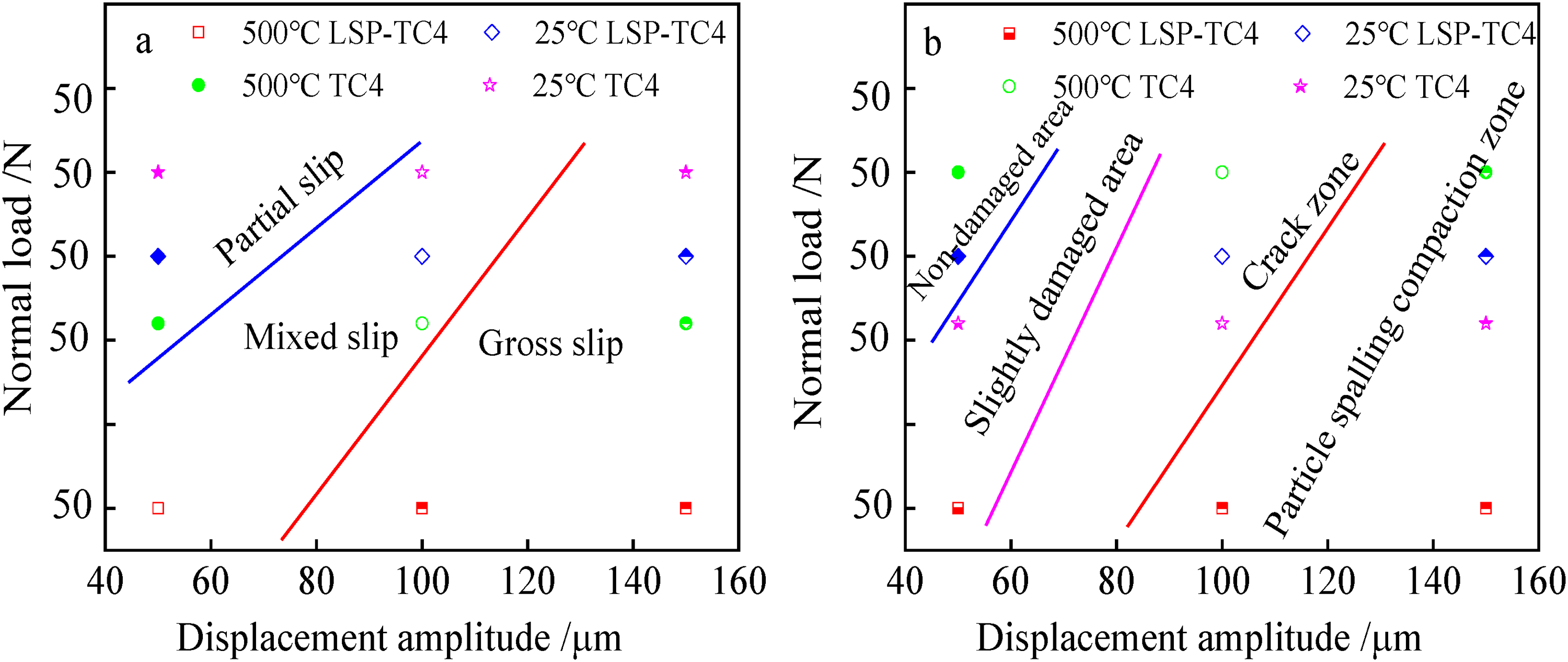
Fretting diagrams of the second-class response of TC4 and LSP–TC4 alloy at 25 °C and 500 °C.
Micro-element analysis
Figures 11 and 12 show the distributions of Ti, O and Fe elements in the contact areas of the TC4 and LSP–TC4 alloys at 25 °C and 500 °C, respectively. The results are presented as EDS maps and energy spectra. The enhanced O and Fe contents and decreased Ti content can be explained by adhesion on the friction surface and the transfer of material in the contact area. The oxidation reaction and adhesion effect were greater on the LSP surface than on the substrate surface, as evidenced by the brightness levels of the EDS mappings in the contact area at 25 °C (Figure 11). At 500 °C, the O and Fe elements in the EDS mappings were brighter than at 25 °C (cf. Figures 11 and 12). The friction contact areas of both metals were severely oxidised and adhered with particles, which moderated the abrasive wear and sliding damage. In summary, easy adherence and oxidation on the hard reinforced metal during the friction process effectively avoided abrasive wear and material loss.
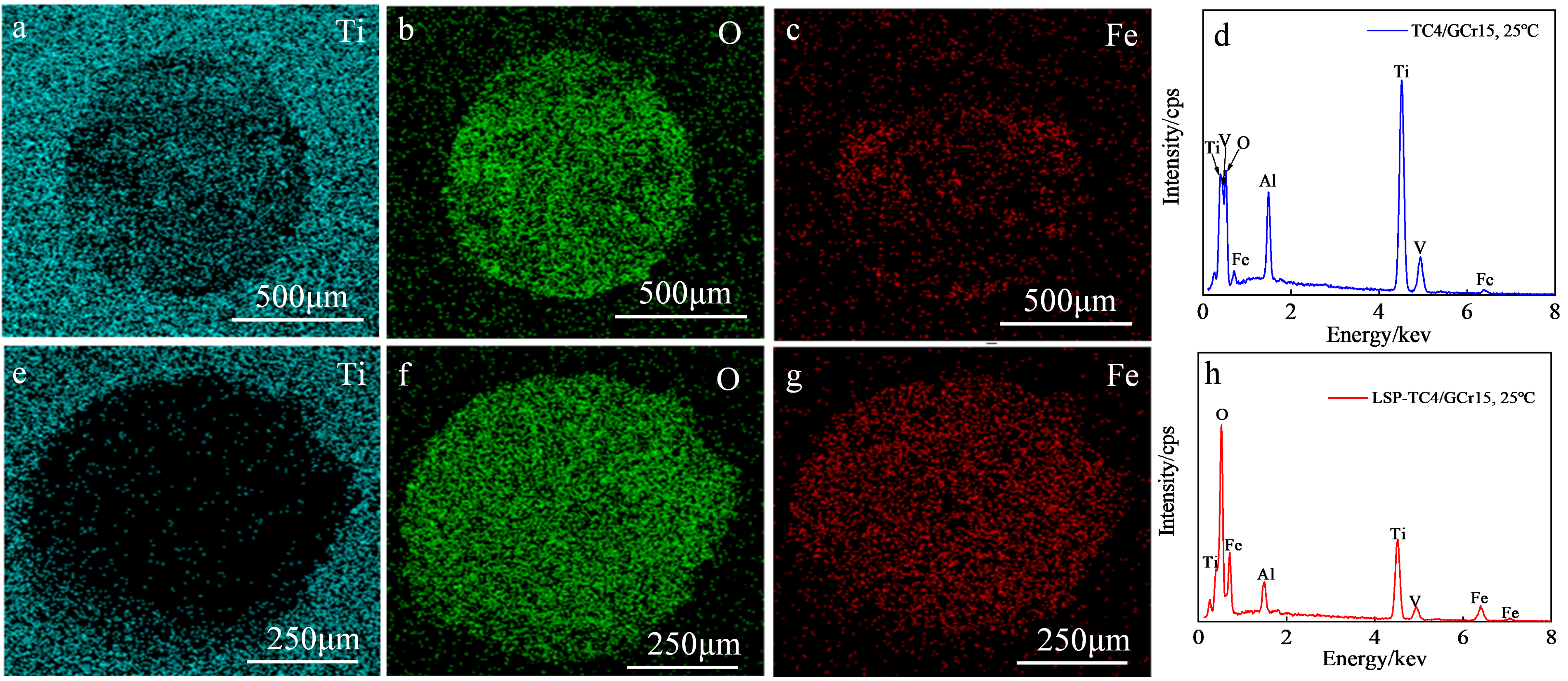
Energy dispersive X-ray spectroscopy (EDS) mappings and energy spectra of (a–d) TC4 alloy and (e–h) LSP–TC4 alloy at 25 °C.
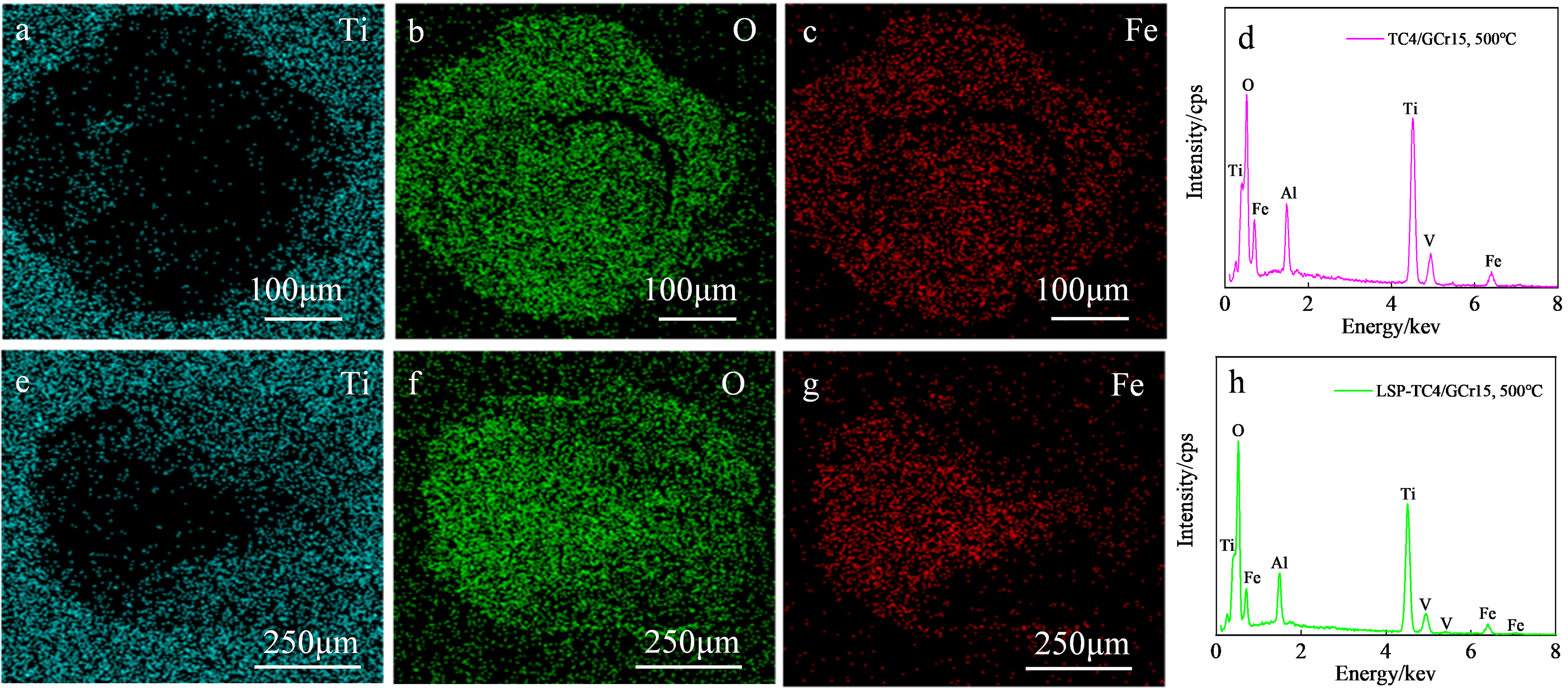
Energy dispersive X-ray spectroscopy (EDS) mappings and energy spectra of (a–d) TC4 alloy and (e–h) LSP–TC4 alloy at 500 °C.
To determine the element distributions in the friction contact areas, EDS maps of the fretting wear spots on the TC4 and LSP–TC4 alloys were obtained. The surface elements distributed in this region were Ti, O, Fe and Al (Figure 13). At 25 °C, the TC4 alloy surface was dominated by Ti and the O content was low. In contrast, the LSP–TC4 alloy presented a higher proportion of O than Ti because the oxidation reaction (accompanied by grain refinement) occurred on this surface. This result clarifies that the wear of LSP–TC4, which easily formed third bodies, was accompanied by oxidation wear that inhibited direct wear of the underlying metal. At 500 °C, oxidation dominated because the O content increased and the Ti content decreased; meanwhile, more of the Fe element was transferred from the GCr15 steel ball than at 25 °C. Figure 13(d) compares the contact-friction surface structures of the TC4 and LSP–TC4 alloys. The diffraction spectra of TC4 display the characteristic peaks of α-Ti, whereas the LSP–TC4 spectra display the characteristic peaks of TiO2 and Fe2O3 in both temperature environments (25 °C and 500 °C). The intensities of the oxide diffraction peaks were considerably higher at 500 °C than at 25 °C.
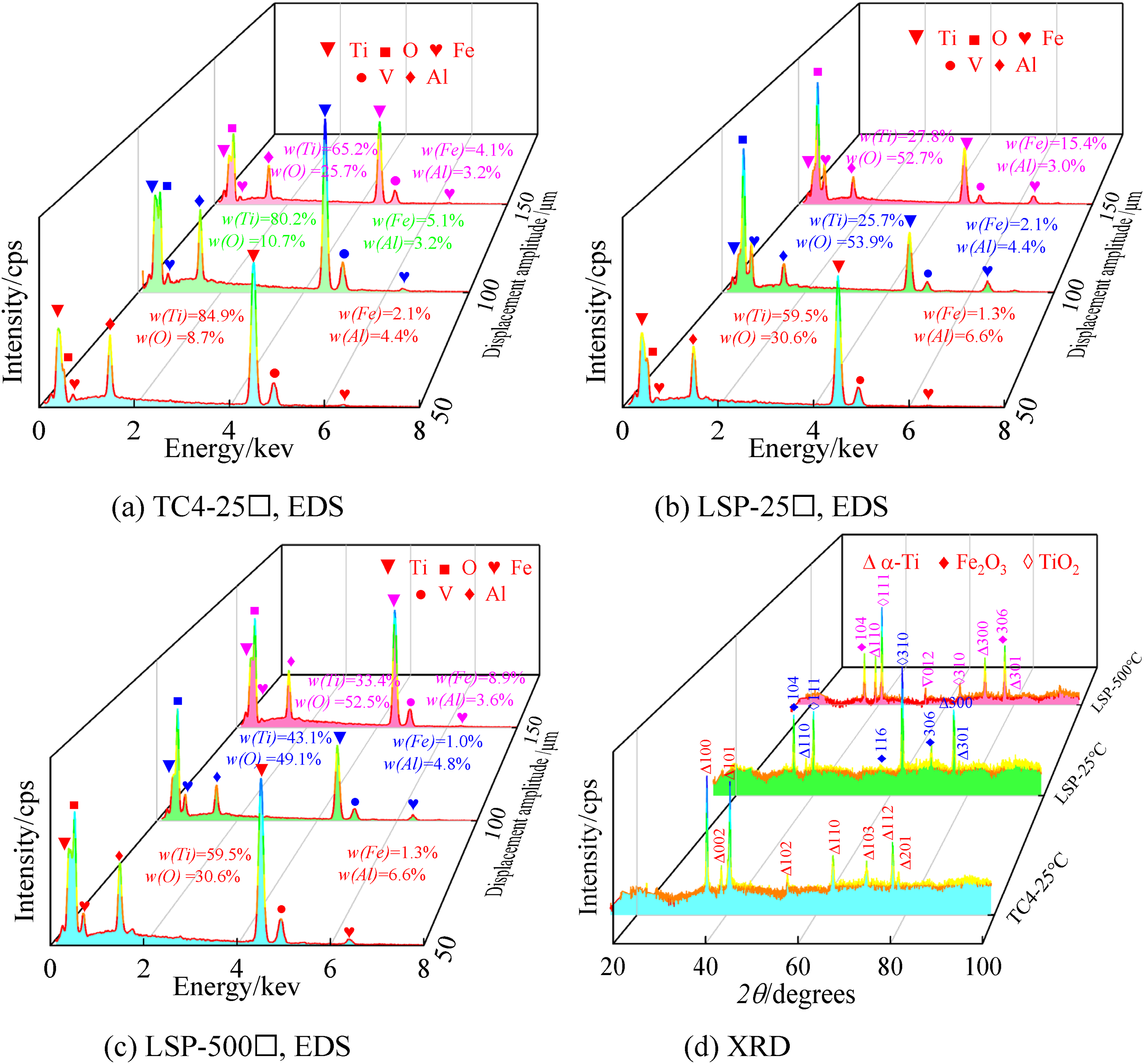
EDS and XRD analyses of the wear contact areas of TC4 and LSP–TC4 alloys in gross slip mode at 25 °C and 500 °C: (a) TC4-25 °C, EDS; (b) LSP-25 °C, EDS; (c) LSP-500 °C, EDS; and (d) XRD.
Evolution of the wear mechanism
Comparing the SEM morphologies of the contact areas under different displacements, this subsection explores the micro-motion wear mechanism of the LSP nanocrystalline layer at 500 °C. As shown in Figure 12, the friction contact area was covered by a black oxide burning layer formed by grinding particles and mechanical rolling. 29 Subsurface sprouting cracks caused by the slippery edges of the contact area intersected with the surface cracks, accumulating plastic strain energy at the viscous–slip boundary and leading to laminar detachment. In the contact centre, where adhesion was weakened and removed, strips of spalling and flakes formed along the fretting direction. At a displacement of 50 μm, the wear was dominated by adhesive and oxidation wear and fatigue wear was slight. Elastic deformation was aggravated in the contact area and adhesion increased because the test equipment was less rigid than required. 25 In the frictional contact area where partial stress was concentrated, small spalling pits were formed through the fracturing of micro-convex body adhesions. Meanwhile, furrows along the slip direction and micro-cracks formed on the contact surface. At displacements of 100 and 150 μm, the wear mechanism was dominated by oxidation and adhesive wear and abrasive wear was slight. However, at 150 μm, the speed of the wear slightly exceeded the speed of crack expansion. Therefore, the contact surface showed a wide distribution of abrasive chips, while crack formations and expansions were limited to the crater.
Figure 14 shows SEM images of the fretting wear areas, together with schematics of the material surface, during the microstructural evolution of LSP–TC4 alloy. This figure is based on maps of the fretting operation and fretting wear morphologies. The straight PSR under smaller displacement amplitude was an elastic-deformation coordination phase formed by the contact behaviour at the sticky centre and slightly slippery edges. The main wear mechanisms were adhesive wear, fatigue crack and oxidation wear. As the displacement amplitude increased, the micro-action operation status changed to elliptic MSR, which describes a plastic-deformation coordinated adhesive zone under coordinated elastic and plastic mechanisms in a hybrid slip state. This state was associated with severe surface-wear damage, adhesion fracture and oxidation and contact-edge sliding with slight abrasive wear. When the micro-motion operation status changed to GSR, describing a slip state governed by plastic deformation coordination, adhered abrasive particles were released and ploughed the matrix material. Meanwhile, the slip area was positively correlated with displacement. The main damage mechanisms were fatigue peeling, abrasive wear and oxidation wear.
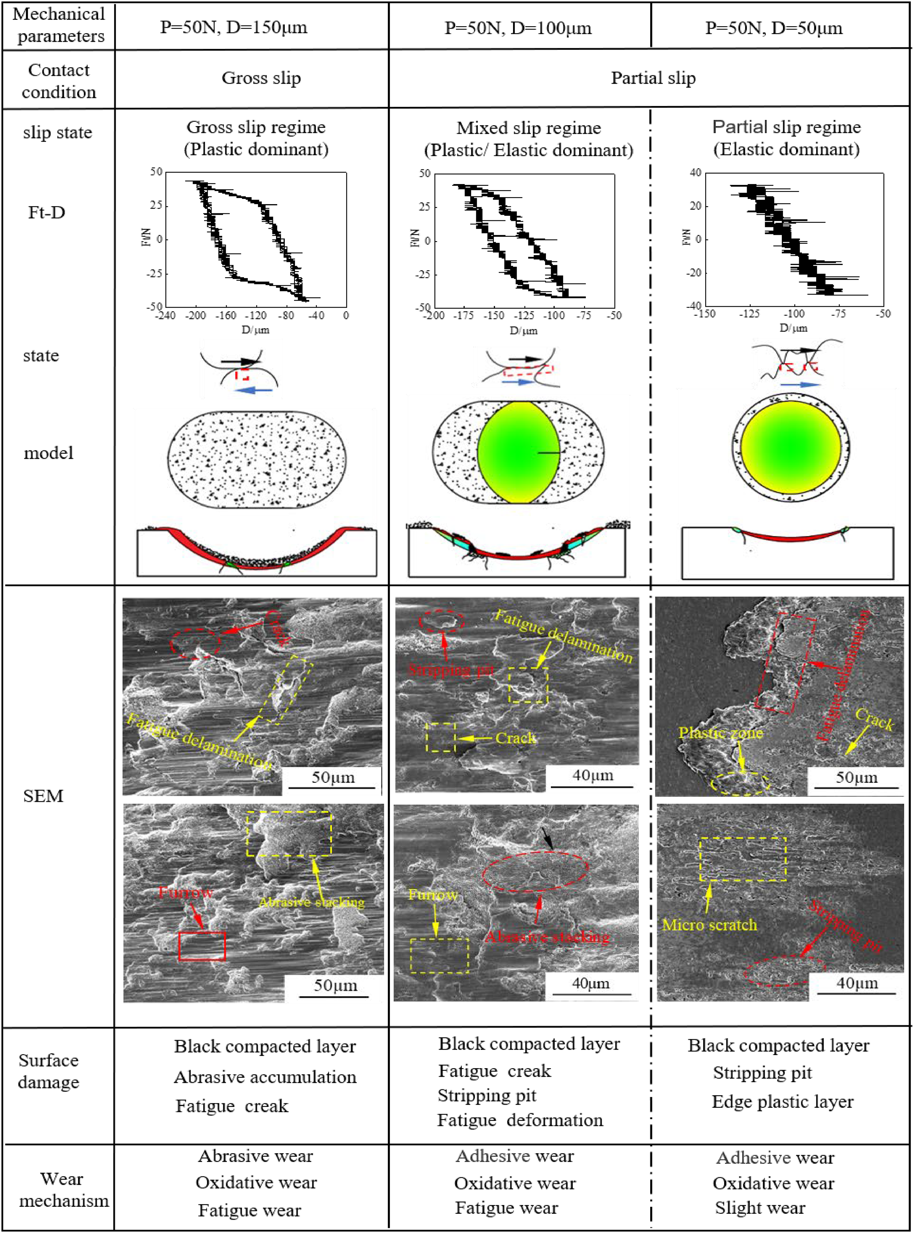
Surface microstructures of the contact areas of LSP–TC4 alloy under different displacement amplitudes at 500 °C.
Conclusions
The conclusions of the study are summarised below.
LSP technology forms a micro-textured nanocrystalline layer on TC4 alloy, optimising the surface structure and thereby improving the fatigue properties of the material, inhibiting crack initiation during friction, and improving the friction properties of the interface. Under high-temperature conditions, a third body contact area with shear resistance and lubricating protection formed on the surface of the alloy. However, relaxation of the LSP residual stress affected the overall mechanical properties of the newly exposed metal; moreover, abrasive wear aggravated the loss of materials and weakened the protective effect of the contact area. Under the same displacement amplitude, LSP–TC4/GCr15 exhibited a lower friction coefficient at 500 °C than at 25 °C but a higher wear rate than TC4/GCr15. The fretting operating state determined the wear mechanism of the LSP nanocrystal layer. At 25 °C, the fretting region was composed of PSR, MSR and GSR and the fretting wear resistance was stable. At 500 °C, the fretting region consisted only of MSR and GSR and the oxidation properties of the metal material were enhanced. The dense oxide layer formed in situ on the contact surface protected the matrix materials. The displacement amplitude affected the behaviour of abrasive particles in the contact zone. Under small displacement amplitudes, particles adhered at the centre of the contact area while edge-sliding behaviour caused fatigue wear. Under large displacement amplitudes, the abrasive particles remained in the contact zone and a third body formed to protect the base metal through oxidation-crushing and re-oxidation-compaction. LSP changed the internal structure of the titanium alloys, inducing grain thinning that inhibited crack propagation and formed micro-cracks, thus improving the alloy properties.
Footnotes
Data availability
Derived data supporting the findings of this study are available from the corresponding authors (Ding Wanwu) on request
Declaration of conflicting interests
The authors declared no potential conflicts of interest with respect to the research, authorship, and/or publication of this article.
Funding
The authors disclosed receipt of the following financial support for the research, authorship, and/or publication of this article: This work was supported by the National Key R&D Program of China (Grant No.2020YFB2010001). Industrial Support Project of Education Department of Gansu Province (22JR5RA258).