
Abstract
In this study, some of the optimal parameters for a new-style marine axial flow fan are defined by using numerical simulation and experimental tests with a large marine axial flow fan, based on the analysis of the blade perforation’s influences on its internal flow field and aerodynamic noise characteristics. Test result shows that the noise reduction for the axial flow fan with perforated blade is about 3 dB when the blade perforation diameter D is 10 mm and its deflection angle α is 45°. The results of the study show that there is an inhibitory effect on the discrete noise of axial flow fan with perforated blade on the tip area, and its total noise level emerged as the fluctuated distribution characteristics with the increase in the perforation diameter D and reduced along with the increase in the deflection of perforation angle α, at the same time varied as a linear characteristics, which can be reasonably explained by the acoustic interference theory. The results of the study have also further confirmed that the improvement of the flow of axial flow fan with perforated blade helps to reduce the pressure pulsation amplitude caused by the turbulence of the blade surface boundary layer, thereby suppressing the back-flow and vortex from the pressure surface to the suction surface efficiently. It is indicated that the improved vortex shedding phenomenon at the blade trailing edge after perforation on the area of blade tip is the main reason for the aerodynamic noise reduction of axial flow fan.
Introduction
As a key equipment of ship cabins, large marine axial flow fans (AFFs) are widely used in large ships for ventilation and air exchange. Since AFFs produce more noise, the aerodynamic noise evaluation becomes one of the important indexes that evaluate the AFF’s performances. 1 Thus, it is necessary to effectively reduce the aerodynamic noise of AFFs. Through a comparative analysis of various noise reduction technologies, it has been found that noise source modifications are the most economical and feasible.2,3 It is feasible to consider noise control methods at the design stage. This is illustrated by Tandan, 4 who describes some methods for noise control in the design stage of the equipment. Noise reduction is achieved by modifying the noise-producing equipment. This method is applied by Duncan and Dawson 5 to axial flow machines, and they obtained a large reduction in discrete noise through a suitable choice of blade and vane numbers. Cattanei et al. 6 present a method for the reduction of tonal nose from axial flow rotors by irregular spacing of blades. A local convexity-preserving structure at leading edge based on Bezier function method has been proposed by Zhou and Li, 7 which is beneficial for the noise reduction without decreasing the performance of axial fans. You and Chen 8 designed an axial fan blade with a serrated trailing edge (TE), which not only effectively reduces rotor wake, but also decreases aerodynamic noise. Rama Krishna and Rama Krishna 9 replace the straight blades with airfoil blade, and the numerical simulation results show that the lowest sound pressure level is 65.4 dB, and the simulation results are verified by experiment.
The research on axial flow fans usually combines numerical and experimental methods,10–15 which is a common research method. 16 The experimental methods are based on the following researches. Yang and Hua 17 did experimental research on the aerodynamic performance of low-pressure AFF with radial, forward-skewed and backward-skewed blades. Yang and Hua 18 described the flow mechanism analysis and experimental study of a forward-skewed impeller and a radial impeller in low pressure axial fan. Compared to the radial blade, the forward-skewed blade is proved to be more efficient, total pressure radio, stable operating range and less aerodynamic noise. Velarde-Suarez 19 presented an experimental study on the reduction of aerodynamic tonal noise of forward-skewed centrifugal fan by modifying the volute tongue geometry. Grilliat 20 performed an experimental study on a single airfoil at a low Mach number to investigate the tip leakage flow and the associated broadband noise in the anechoic wind tunnel.
Currently, research on reducing the noise of small AFFs has yielded positive results.21–23 The results of Li and Qian,24–26 by applying the method of numerical simulation, showed that it is feasible to reduce the noise of small AFFs by perforating on the blade. The numerical and experimental investigations of small AFFs perforated on the blade root by Zhang and Yingzi 27 indicated that the smooth pressure distribution on the blade surface is the main reason for noise reduction of small AFFs perforated on the blade root. After conducting researches on the AFF’s noise with different tip clearance, Fukano and Jang 28 found that the vortex caused by tip leakage is the main reason for noise production. Wang and Li 29 have already established a statistical model to predict broadband turbulence noise of axial flow cooling fan, thereby designing an optimized new-style AFF which produces noise of 2 dB less than before, and verified the feasibility of the model by experiment. While the studies above mainly focused on small and medium AFF, there are few records on the noise reduction method for large marine AFF.
The idea of perforation of blades comes from perforated liners, which are efficient in noise damping. Numerical and experimental investigations of the acoustic damping effect of single-layer perforated liners were conducted by Zhao.30,31 It is shown experimentally that increasing the liner’s open area ratio can increase its damping effect at higher frequency.
In this paper, the effects on aerodynamic performance and noise of large marine AFF with perforated blade are studied and the main causes of noise reduction are analyzed by numerical and experimental investigations. The research results will provide the reference for reducing the noise of the large marine AFF in use.
The calculation model and numerical method
Design of perforation on the blade
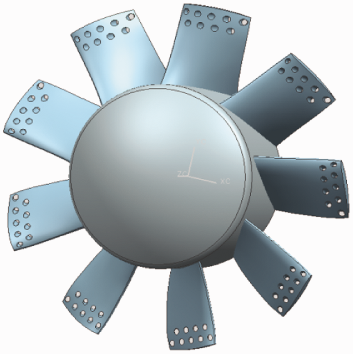
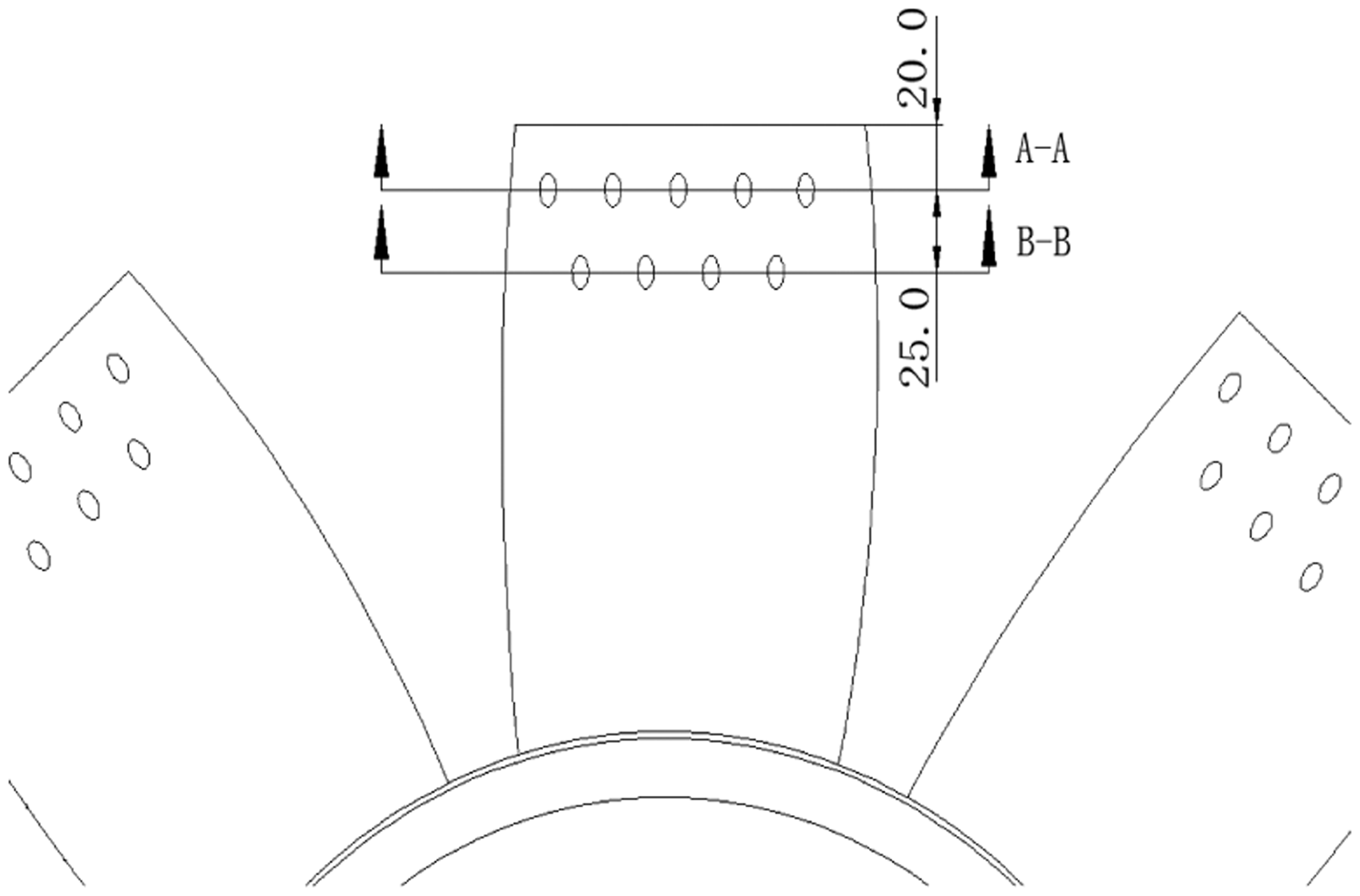
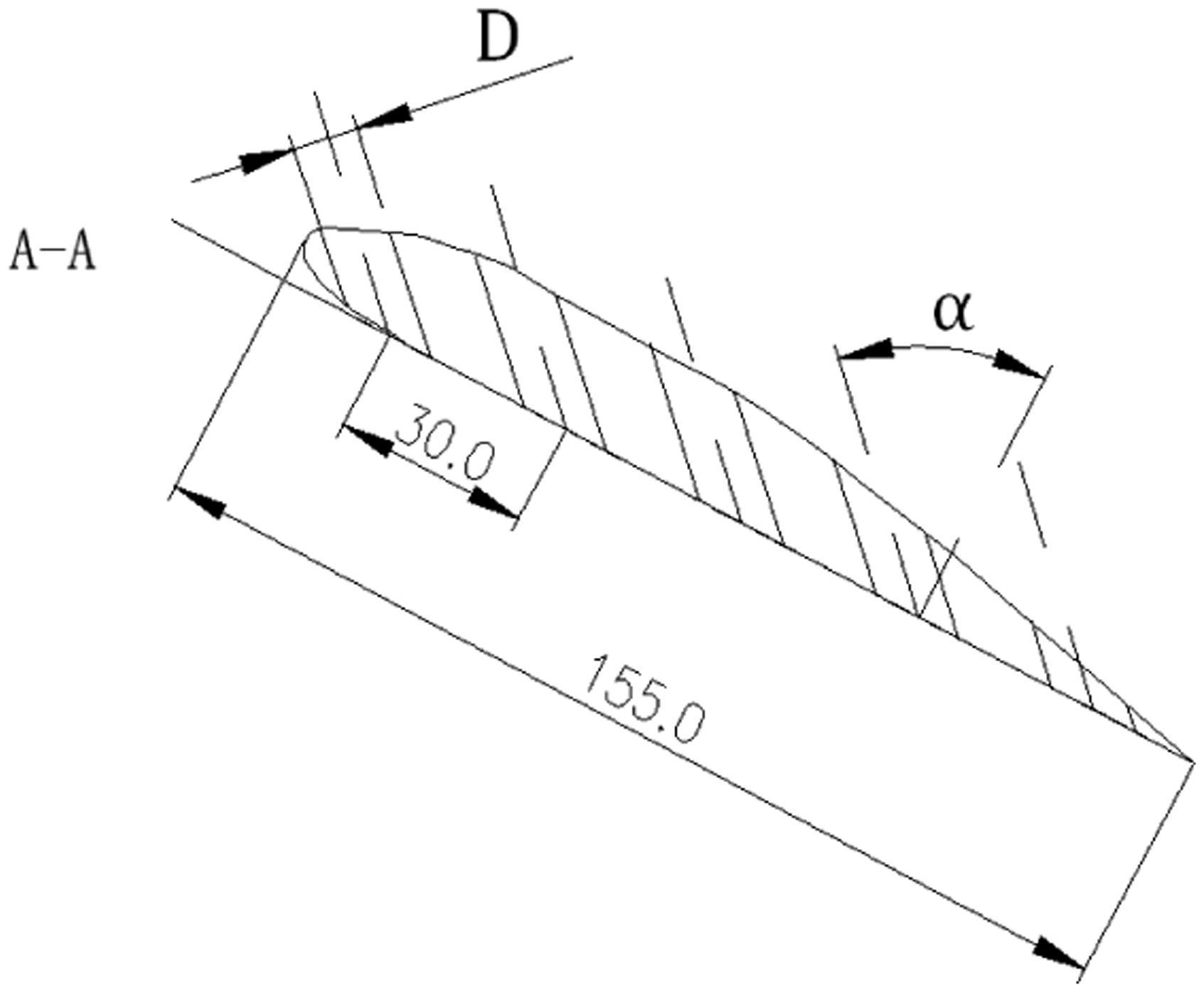
In this study, a particular type of marine AFF is chosen, as shown in Figure 1. Its impeller diameter is 800 mm, hub ratio 0.53, number of blades 9, tip clearance 3 mm, the rated rotating speed 1460 r/min and the rated air volume is 21,000 m3/h. On the basis of the prototype fan model, a reasonable perforation design is done in the region of the blade tip, as shown in Figure 2. From the tip of 25 and 45 mm, as shown in Figure 3, the position of two row holes is determined respectively. Perforation parameters such as the pore diameter D and perforation deflection angle α are shown in Figure 4, and the distance between the axis of the two adjacent holes on the same row is 30 mm.
The prototype fan model. The fan model with perforated blade. Perforation position diagram. Perforation diameter diagram.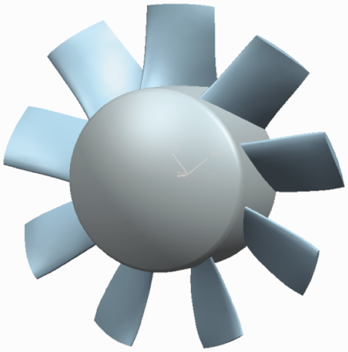
Calculation model of flow field
To ensure the full development of the flow field, the calculation area of flow field should be designed reasonably. The computational domain of the numerical simulation for AFF is divided into four parts, i.e. inlet pipe, outlet pipe, rotary fluid region and the tip clearance region, as shown in Figure 5. The nonstructural grid (tetrahedral T-grid) is used in the rotary fluid region and the tip clearance region, where the flow is more complicated, while the structural grid (hexahedral cooper mesh) is used in the region of the inlet pipe and outlet pipe. The total number of grids is about 3 millions, and the area of EquiAngle Skew mainly varies between 0.2 and 0.7.
Computational domain of numerical simulation for AFF.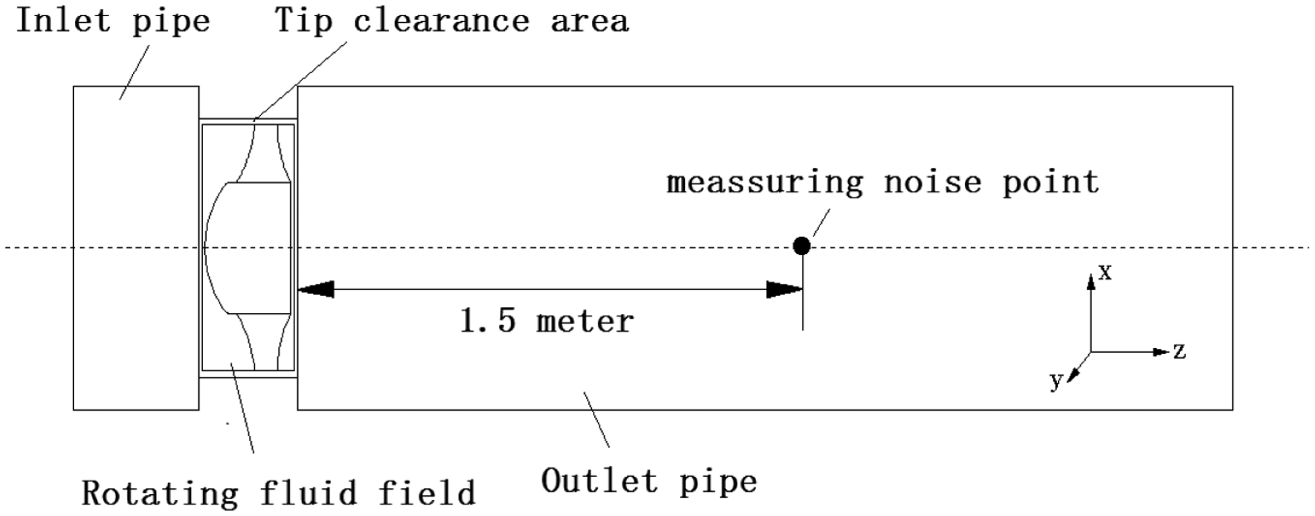
Setting of numerical simulation circumstances
In setting of numerical simulation circumstances, Navier–Stokes Equation is used to solve the calculation of unsteady flow; the PISO algorithm is used to solve the coupling between velocity and pressure, and the central difference scheme in PRESTO method is used for numerical discretization. Setting of the boundary condition uses the rate of mass flow for inlet, which is perpendicular to the pressure boundary for outlet and the no-slip boundary for solid wall. The interface boundary property is used between the rotary fluid region and the tip clearance region. And the time step of the unsteady calculation is 1 × 10⁻⁴ s. The calculation is considered to be convergent until the unbalanced error of mass and momentum is less than 0.1%. On the basis of numerical simulation of the AFF flow field, the Ffowcs Williams-Hawkings (FW-H) acoustic model is used to solve its acoustic field. And the noise frequency spectrum distribution for the AFF is acquired through the data processing by Fast Fourier Transformation (FFT), where the data are gathered at the noise monitoring point 1.5 m from the central axis of the impeller.
The selection of perforation parameters on the blade
Comparison of calculation scheme and results.
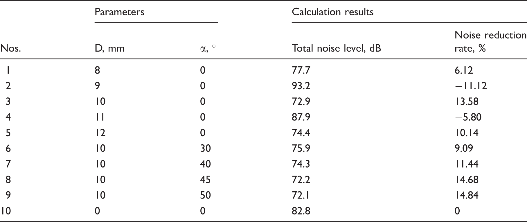
D: perforation diameter; α: perforation deflection angle.
In case of optimal perforation diameter D = 10 mm, four perforation deflection angles α selected to conduct calculation, respectively, are 30°, 40°, 45° and 50°, as shown in Table 1 (No. 6–No. 9). It can be found that the noise reduction effect of No. 7 and No. 8 is most obvious, and the difference of overall sound pressure level between No. 7 and No. 8 is very small. So considering the processing difficulty in perforation, the optimal perforation deflection angle α is determined as 5°.
Analyzing the influences of perforation parameters on noise reduction for AFF, the total noise level does not present the obvious trend to the variation of perforation diameter D. With the increase of D, the trend of total noise level presents the characteristics of the fluctuating distribution. Simultaneously, it can be found that, when D is an even number, the noise reduction rate is positive, and the total noise level decreases; when D is an odd number, the noise reduction rate is negative, and the noise level increases. This phenomenon explains the interference of sound waves that has been produced by perforation on the blade and by the impeller’s rotation. According to the coherence of sound waves, the sound waves with same frequency and fixed phase difference can be be interfered by others. 32 When the sound waves produced by perforation on the blade and by impeller’s rotation fluctuate in the same phase, the amplitude and sound pressure of the synthesized sound field are, respectively, equal to the sum of the two sonic amplitude and sound pressure, i.e. the noise increases. When the sound waves produced by the perforation on the blade and by impeller’s rotation fluctuate in the contrary phase, the amplitude and sound pressure of the synthesized sound field are, respectively, equal to the difference of the two sonic amplitude and sound pressure, i.e. the noise decreases. So, it can be confirmed that the influences of different perforation diameters on the phase of sound waves produced by perforation on the blade have certain regularity; therefore, the total noise level for AFF presents a kind of fluctuated characteristic along with the change of perforation diameter.
Meanwhile, when D is fixed, the total noise level for AFF will decrease along with the increasing of perforation deflection angle α, i.e. the noise reduction rate increases gradually and presents to be a linear variation. This kind of phenomenon can also be explained reasonably by acoustic interference theory, in which, the change of perforation deflection angle α altered the acoustic phase produced by perforation on the blade so that the total noise level decreases when the value of α increases; on the other hand, due to the influences of α on the acoustic phase are very small, the total noise level changes little in synthesis sound field.
Experimental testing method
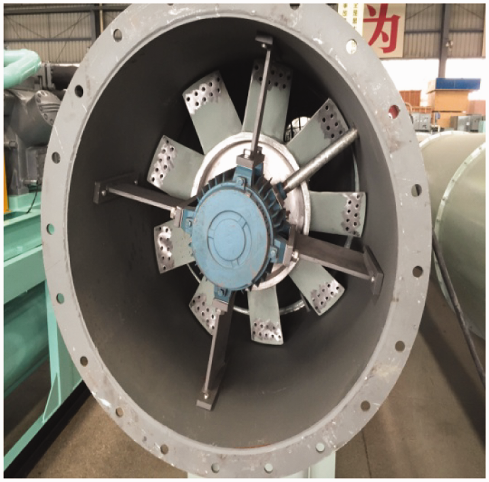
The experiments for performance testing of AFF is conducted on the duct, which is 2.5 m long, 0.8 m diameter, as shown in Figure 6. The experimental AFF with perforation, as shown in Figure 7, is laid at the end of the duct. The static pressure of experiment can be measured by the micro-manometers with the hose connected to the small holes excavated on the tube wall. The impeller is driven by an electric motor, and the rotating speed is 1460 r/min. After stable running, the corresponding data such as static pressure, rate of flow, etc. could be recorded by adjusting the air grille of duct.
Experimental duct. Experimental perforation AFF.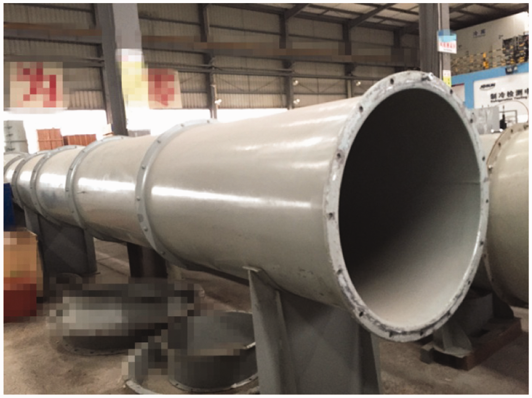
The noise testing system consists of the four-channel signal acquisition instrument obtained from the Oriental Institute (PRC), microphone, laptop, and DASP signal analysis and processing software. The microphone is laid at 1.5 m away from the impeller along the central axis of fan outlet. Noise signal is gathered and transferred by four-channel signal acquisition instrument, and analyzed by DASP signal analysis and processing software.
Experimental results and analysis
Experimental results of the aerodynamic performance
Figure 8 shows the curve of the coefficient between total pressure and rate of flow for the two AFF models before and after perforation. It can be seen that the overall trend of the curves is consistent with the simulation data and experimental data of these two fan models before and after perforation. The total pressure decreases with increasing flow. In the case of the same flow coefficient, the test data is smaller than analog data of the prototype fan. This is because the simulation result conducted in the ideal situation without the deviation of environment and other factors. In contrast to the test data of the fan model before and after the perforation, it can be found that the total pressure for AFF after perforation is smaller than that for prototype AFF because of the airflow passing through the holes directly without the action of blade. It is indicated that perforation on the blade certainly influences the performance of the AFF.
The curve of the coefficient between total pressure and rate of flow.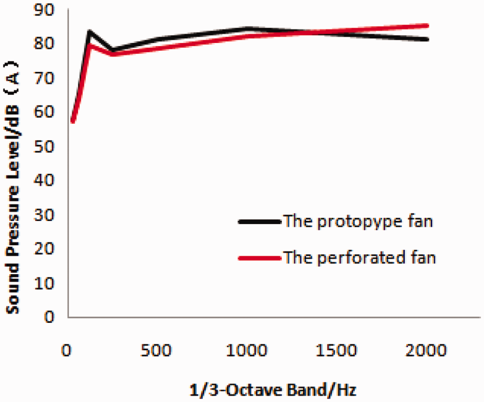
Experimental results of the noise test
Figure 9 shows the weighted sound pressure level of 1/3 octave band at the monitoring point. It can be seen that under the frequency of 1500 Hz, the noise of the AFF with perforation is lower than that of prototype; in the frequency of 125 Hz, the noise reduction is about 3 dB. However, in the mid- and high-frequency bands above 1500 Hz, the noise of AFF with perforation increased slightly. It shows that perforation on the blade has a certain inhibitory effect on the low-frequency noise for AFF.
A weighted sound pressure level spectra of 1/3 octave band at the monitoring point.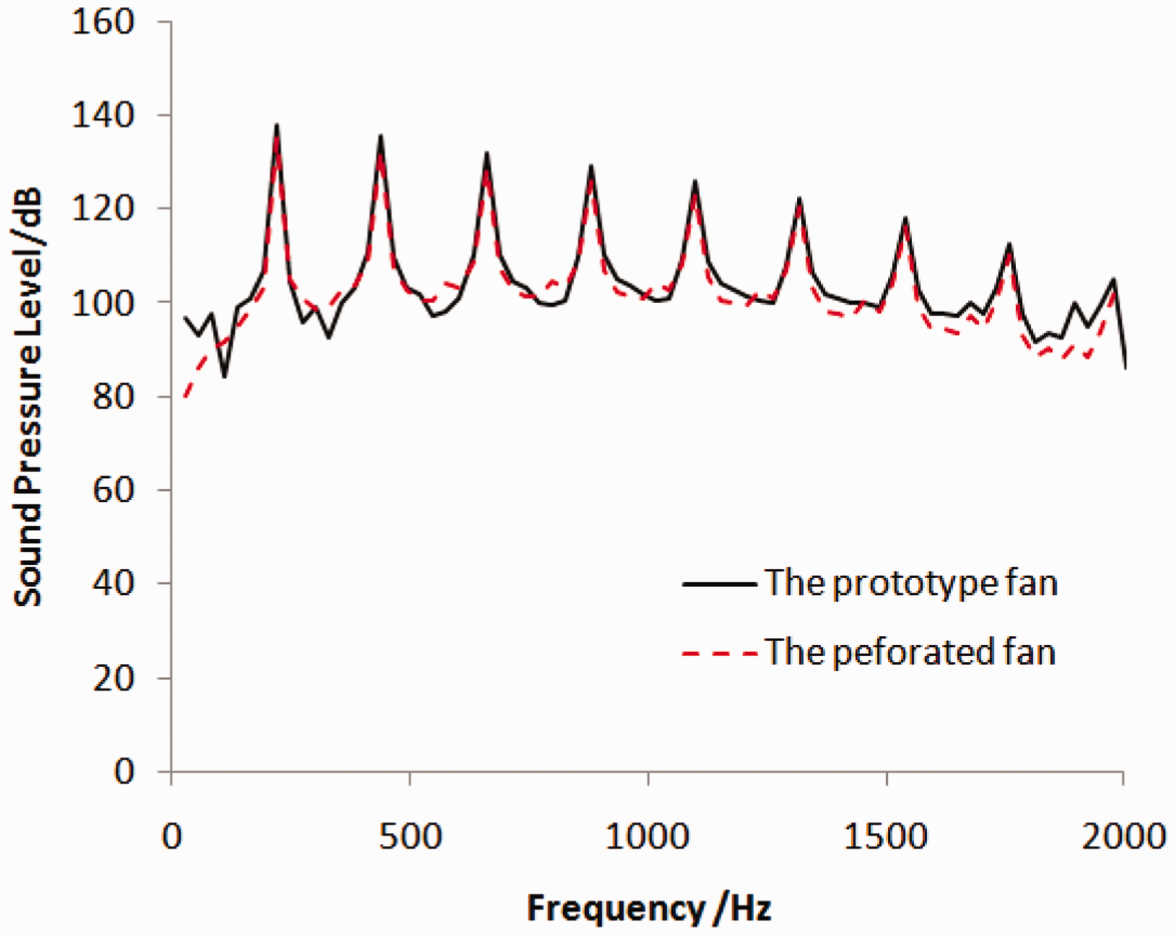
Noise reduction mechanism analysis of perforated blade
The internal flow characteristics of AFF are key factors that affect its performance and noise. Hence, it is crucial to analyze the internal flow characteristics of AFF for research on the noise reduction mechanism of AFF with perforated blade.
Figure 10 shows the velocity streamline distribution of axial section of impeller before and after perforation. It can be seen that the velocity streamline distribution is similar to each other. At the blade tip there are tip clearance vortexes caused by the blade tip clearance, and at the outlet of the impeller there are greater back-flow regions on both sides of the outlet pipe. There are less back-flow regions after perforation on the blade and they move downstream. The improvement of the flow suppresses the separation of the flow, which contributes to reduce the pressure pulsation amplitude caused by turbulence flow on the blade surface boundary layer, to reduce the noise.
The velocity streamline distribution of axial section of impeller: (a) the prototype fan model and (b) the perforation fan model.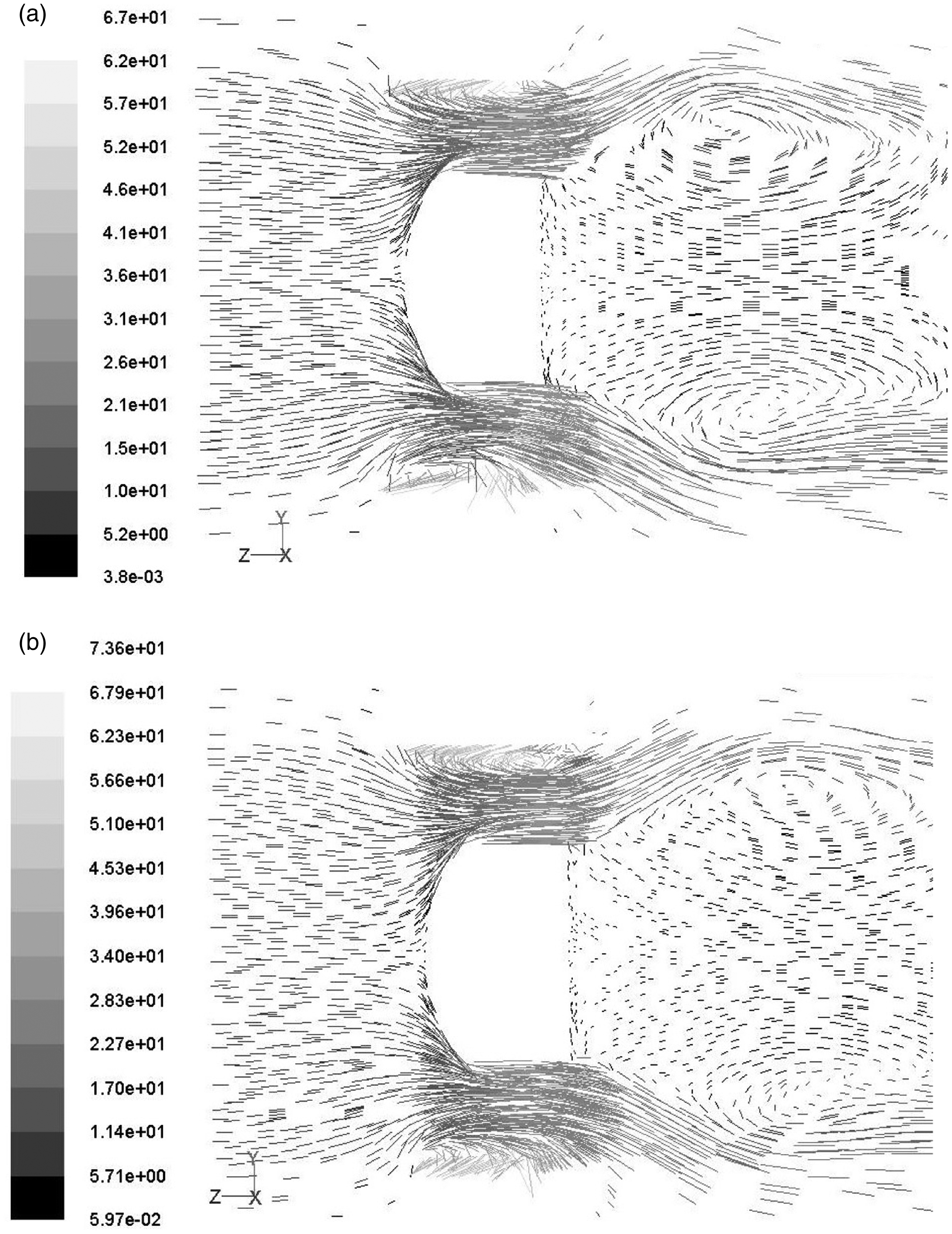
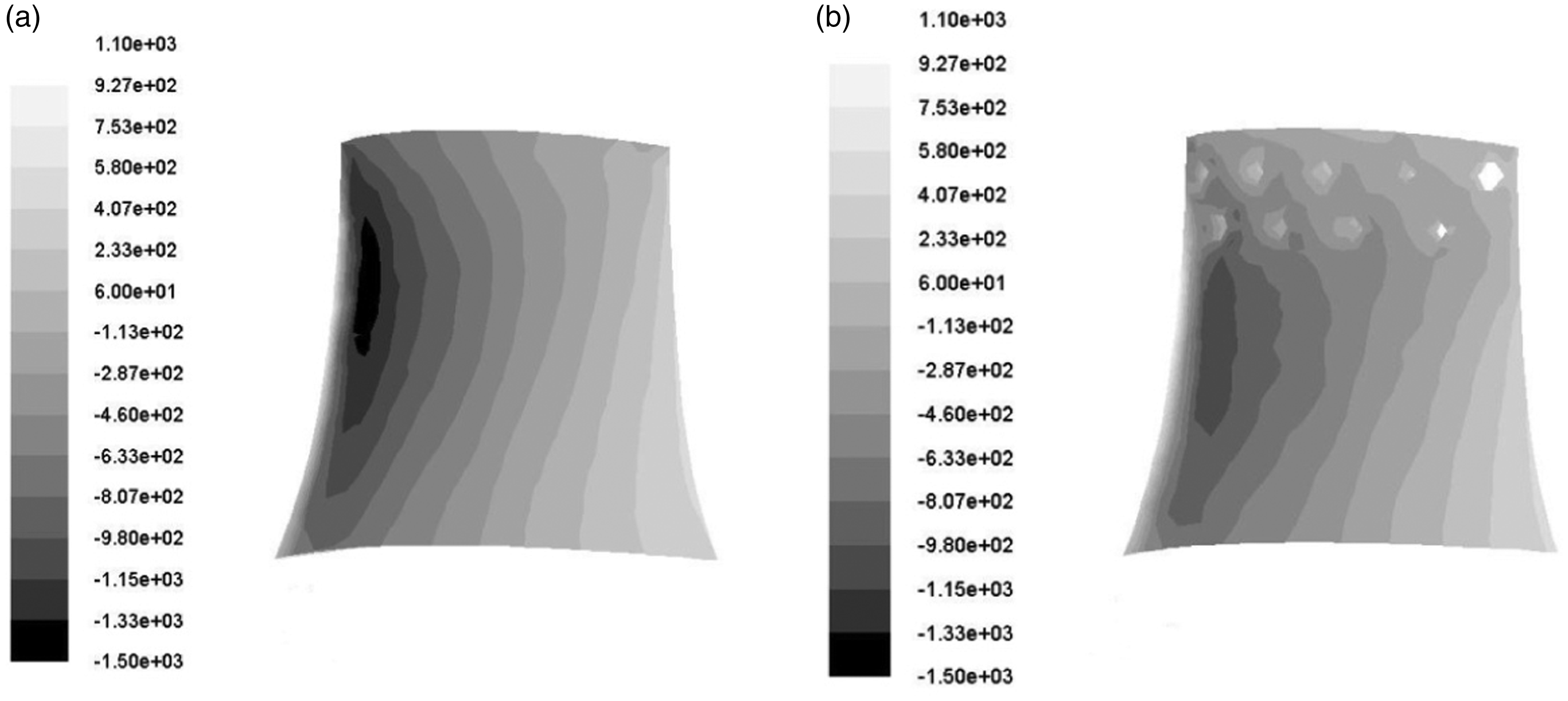
Figures 11 and 12 show the static pressure contour distribution of blade suction surface and blade pressure surface for AFF before and after perforation, respectively. It is obvious that the high pressure area decreases at the blade tip and leading edge on the blade pressure surface, and the static pressure distribution on the surface of blade is more uniform than before. Therefore, the cross flow and the back-flow of air along the pressure surface, and the disturbance flow directing to the blade root slow down, and the turbulent boundary layer becomes small, and finally the loss of flow is reduced. And the low pressure area on blade suction surface moves to the hub and increases slightly because of the influence of the perforation at the blade tip. In consequence, the static pressure difference between the pressure surface and suction surface reduces, and the back-flow and vortex from the pressure surface to suction surface are suppressed, which reduce the turbulence noise of AFF.
Static pressure distribution of blade pressure surface before and after perforation: (a) the prototype fan model and (b) the perforation fan model. Static pressure distribution of blade suction surface before and after perforation: (a) the prototype fan model and (b) the perforation fan model.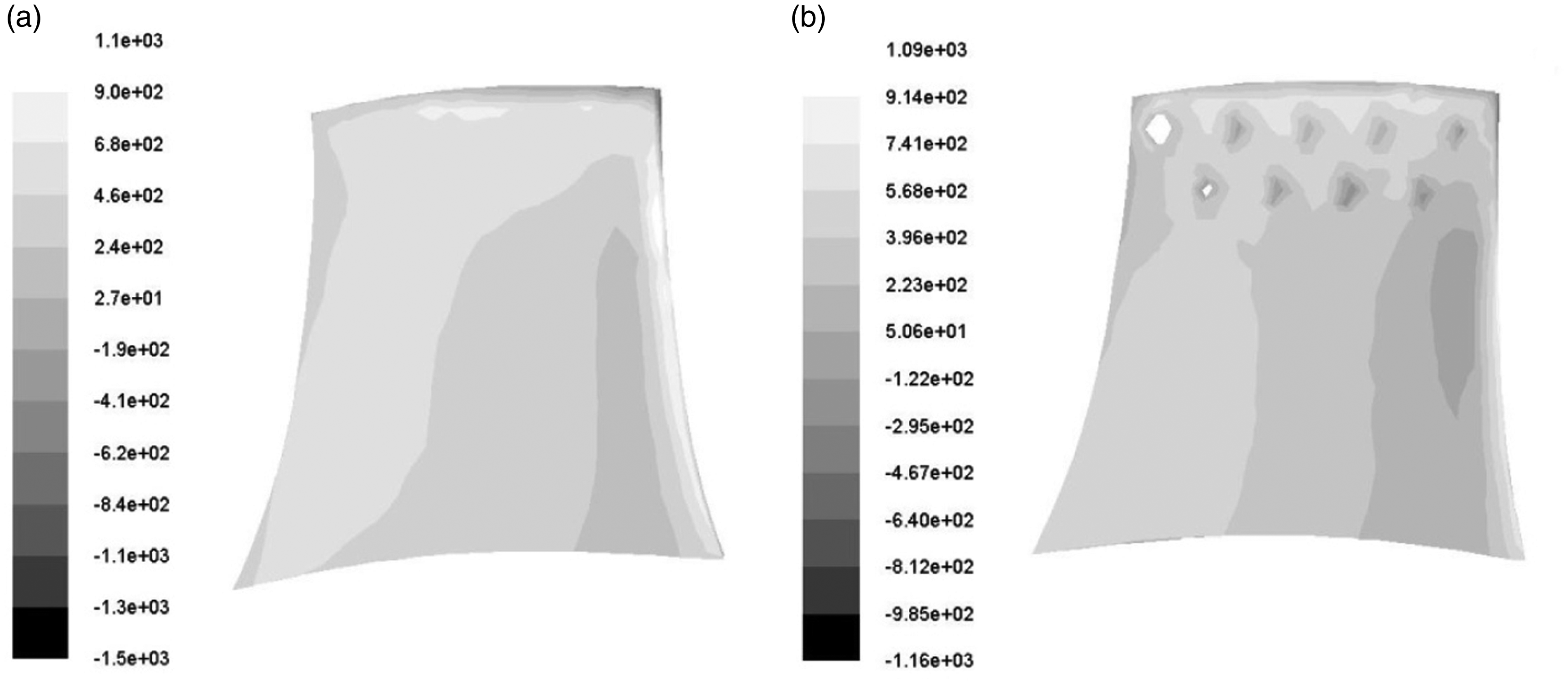
Analyzing the velocity contour distribution of revolution surface located at 150 mm blade height in the flow field before and after perforation, as shown in Figure 13(a), it can be seen that velocity is concentrated and accompanied with vortex shedding phenomenon in the position of the blade trailing edge. According to the vortex sound theory, vortex shedding is the main reason of the vortex noise. And after perforation, as shown in Figure 13(b), this phenomenon is improved. It is indicated that perforation on the blade suppresses the vortex shedding phenomenon at the blade trailing edge, which is one of the main reasons for the aerodynamic reduction.
Velocity contour distribution of revolution surface located at 150 mm blade height: (a) the prototype fan model and (b) the perforation fan model.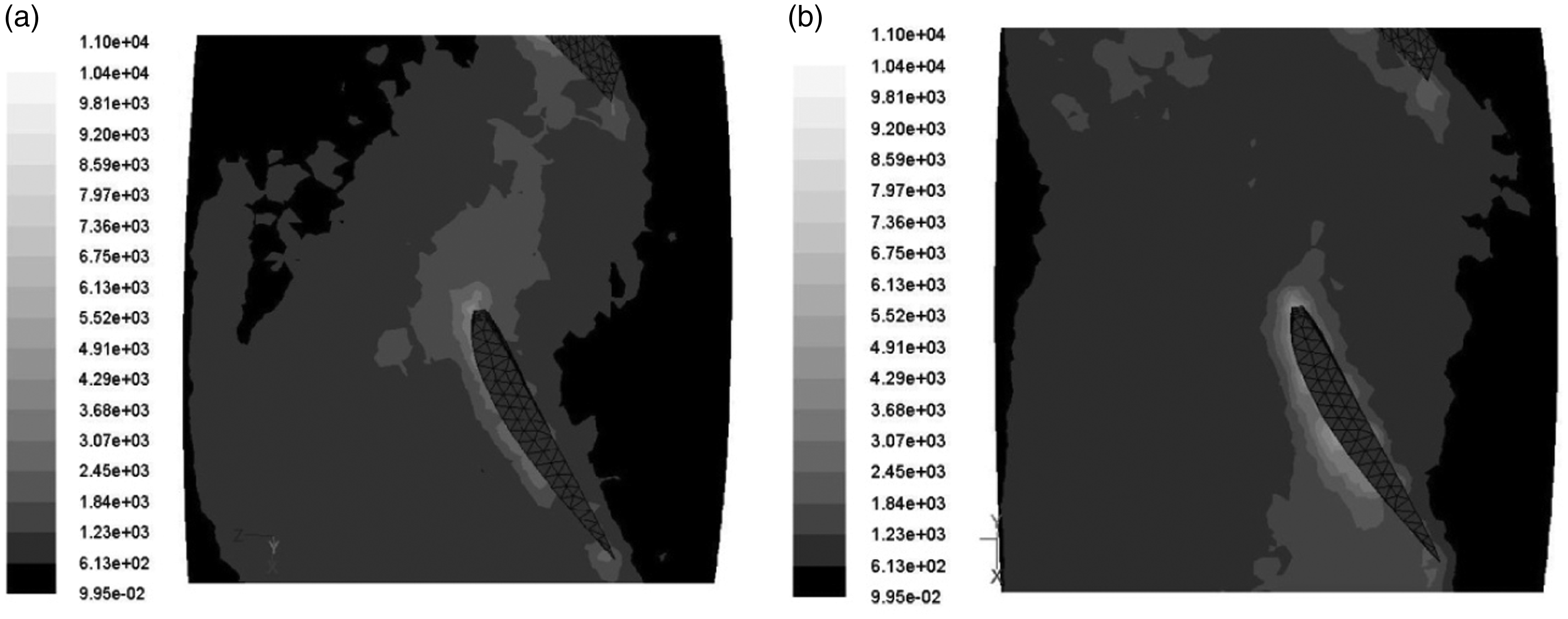
In order to explore the noise characteristics of AFF and the noise reduction mechanism for perforated blade in more detail, the blade tip clearance noise spectrum is observed, as shown in Figure 14. The sound pressure level at tip clearance obviously has discrete spectrum characteristics.
33
The peak sound pressure level is at the fundamental frequency and is harmonic for blade passage, which has a predominant function to the total noise level and reduces gradually with the increase of harmonic frequency. So, the discrete noise composed by the peak sound pressure level is a leading role to the total sound pressure level, which is the main element of the aerodynamic noise.
Noise spectrum at tip clearance before and after perforation.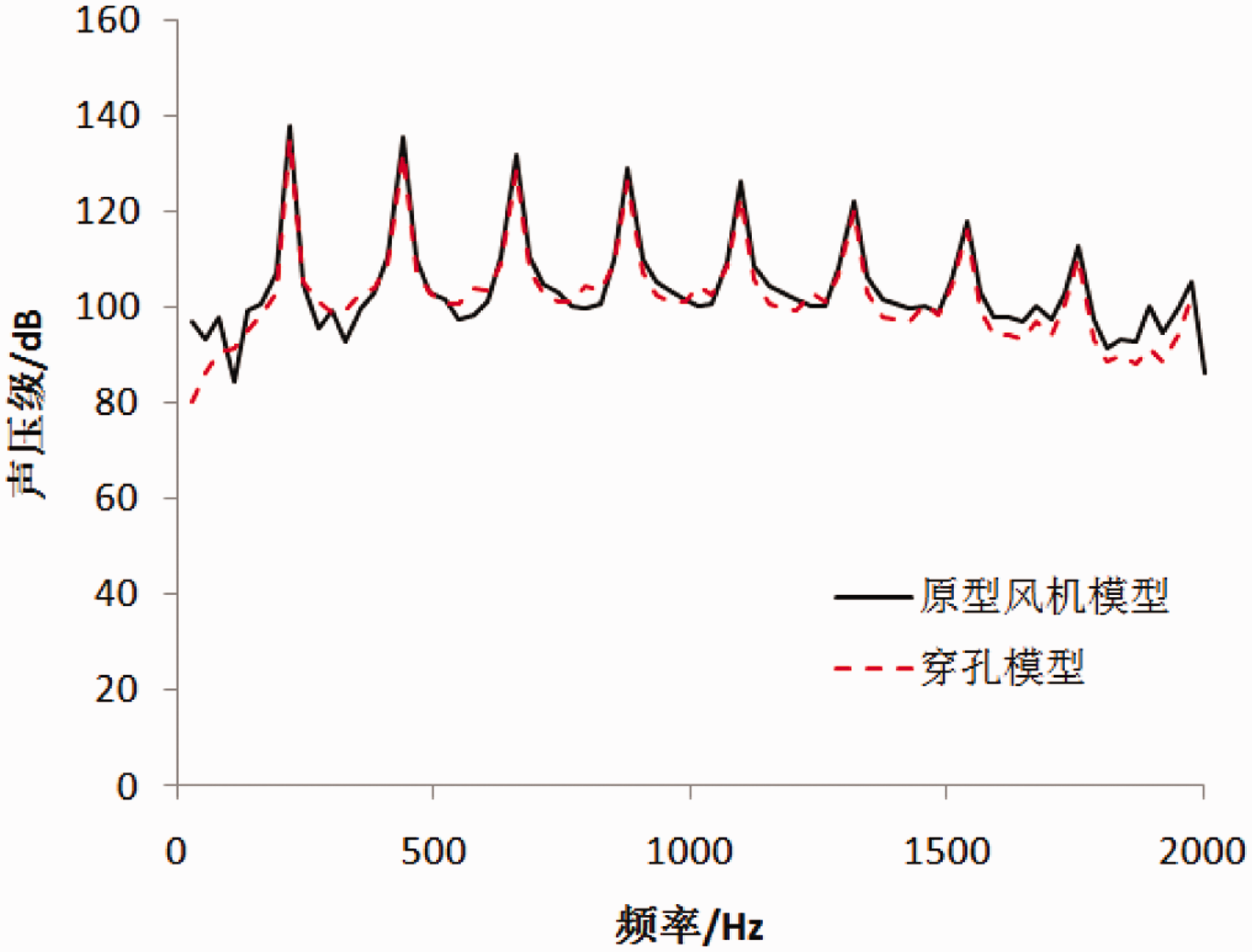
Comparing and analyzing the noise spectrum of AFF before and after perforation, it is observed that their structure is similar and the amplitude is close, but the noise peak reduces about 3 dB after perforation. Because the discrete broadband noise is mainly formed by the turbulence flow in circumference nonuniform flow field caused by the interaction between the flow of the rotating blade and the blade tip leakage, it can be assumed that the perforation on the blade has a certain inhibitory effect on the turbulence flow on the blade surface as well as on the blade tip leakage flow.
Conclusions
By numerical simulation and experimental testing, for a kind of large marine AFF with perforated blade, the effects of the perforated blade on internal flow field and aerodynamic noise characteristic are studied, and the mechanism of noise reduction for AFF with perforation is analyzed. The main conclusions are as follows:
It is found by numerical simulation that perforation on the blades has different degree of influence on the noise of AFF. As shown in this study, when the perforation diameter D is 10 mm and perforation deflection angle α is 45°, the noise reduction effect is best and the noise reduction rate is 14.6%. While analyzing the effect of perforation parameters on the noise reduction AFF, it can be found that the total noise level distribution fluctuates with the increase of the hole diameter, and when the perforation diameter D is fixed, the total noise level distribution reduces along with increasing in the perforation deflection angle α, which is found to be a linear variation. It can be explained reasonably by acoustic interference phenomenon. The results of the experimental tests show that perforation on the blade for AFF certainly influences the performance of AFF. As shown in this study, the total pressure is lower after perforation than before perforation, and the noise decreases to about 3 dB. By analyzing the distribution of internal flow field for AFF, it can be further confirmed that the improvement of the flow of AFF with perforated blade helps to reduce the pressure pulsation amplitude caused by the turbulence of the blade surface boundary layer, thereby the back-flow and vortex from the pressure surface to the suction surface is suppressed efficiently. It is indicated that the improved obviously blade edge vortex shedding phenomenon after perforation on the area of blade tip is the main reason for the aerodynamic noise reduction of the AFF. Meanwhile, perforating on the blade tip region improves the circumference nonuniform flow field caused by the interaction between flow of blade rotating and flow of the blade tip leakage, and also has an inhibitory effect on the discrete broadband noise of AFF.
Declaration of conflicting interests
The author(s) declared no potential conflicts of interest with respect to the research, authorship, and/or publication of this article.
Funding
The author(s) received no financial support for the research, authorship, and/or publication of this article.