
Abstract
This study investigates reducing the vibration of structures under different earthquakes using magnetorheological dampers. To investigate the effect of the magnetorheological damper arrangement on reducing the vibration amplitude of structures, experimental studies are conducted in which magnetorheological dampers are commanded by a robust controller. So, the performance of the system is investigated using different combinations of two magnetorheological dampers on a building and three different arrangements for dampers are considered for experimental study. Additionally, an H∞ controller is designed to determine the voltage transmitted to the magnetorheological dampers. The results show that the magnetorheological damper commanded with the robust controller effectively reduces the vibration of a six-story steel structure. Furthermore, the magnetorheological damper arrangement in which the one end is connected to the ground reduces the vibration amplitudes.
Keywords
Introduction
The control of linear and nonlinear systems equipped with semiactive devices is interesting subject that can be studied both experimentally and theoretically.1–10 In particular, semiactive systems have the reliability of passive systems and consume less energy than active systems. Several systems are used to reduce undesired vibrations that are emitted from buildings. Three types of systems have been developed and successfully studied in the literature. These systems can be classified as passive, active, and semiactive systems. Active and semiactive systems can be controlled electronically. Passive systems are simple, classical systems that are currently used. Their characteristic features cannot be controlled with an external input. Their structure is simple, reliable, and low cost. When varying conditions are considered as the damping force is held constant, their performance is limited. In active systems, the necessary force of the system is achieved using active controllers (i.e. hydraulic cylinders). Such systems achieve high performance over a wide frequency range. Regarding active systems, the use of equipment, such as sensors, servo-valves, and high-energy demand leads to high system costs. However, semiactive systems can act as both active and passive systems. Their performance is similar to active systems. Because semiactive systems can act as a passive system in the case of problems in the control systems, they are more reliable than active systems. Magnetorheological (MR) dampers are semiactive devices that can absorb the vibratory energy according to the motion of the MR damper and input control voltage applied to them. Their advantages are mechanical simplicity, high dynamic range, low power requirements, low cost, large force capacity, and inherit stability. Because of these advantages, these devices are used in many application areas such as suspension systems,5,6,8,9 portal frame structure, 11 and structural control.4,12–25
This study reports the control and various arrangement combinations of two MR dampers that are used to reduce structural vibrations. A number of studies are conducted regarding the control of the MR damper and the arrangement of multiple MR dampers. Dyke et al. 12 employed MR dampers on the first floor of a three-story structure and used a clipped-optimal control strategy with a momentum feedback base. Dyke et al. 13 applied a clipped optimal control algorithm, which was previously tested via simulations, 12 by connecting the MR damper to the test model between the ground floor and first floor. Jansen and Dyke 14 implemented MR dampers in a building model with six degrees of freedom (DOFs); the MR damper was laid out on the first two floors in a parallel configuration. Yi et al. 15 utilized a six-story structural model to test MR dampers located between the ground floor and first floor and between the first floor and second floor. Two different semiactive control algorithms are used, including Lyapunov-based control and clipped optimal control. Aldemir 16 studied the performance of an optimal semicontrolled MR damper in a system with one DOF, which depended on the tuned mass damper for reducing the vibration of the structure. Tusset et al. 11 studied chaotic motions of a portal frame structure under nonideal loading. Two control algorithms are used, including nonlinear feedforward control and state feedback control. Cho et al. 17 implemented an MR damper on the first two floors of a six-story building. Model control was designed for a seismically stimulated six-story structure. Aldemir and Gavin 18 implemented passive, optimal, and pseudoskyhook control in a 1-DOF system and compared the responses of the system. Kim et al. 19 used a three-story structure model and fixed an MR damper on the first floor. A LMI-based semiactive fuzzy logic controller was applied to command the MR damper. Lu et al. 20 investigated the layouts of three MR dampers in a six-story steel frame structural system and compared several semiactive control algorithms, including decentralized sliding mode control, linear quadratic regulator (LQR) control, and passive-on and passive-off control. The MR dampers were fixed to the structure in the four different cases. In the first case, a MR damper was located on the first floor. For the second case, two MR dampers placed on the first and third floors were used. In the third case, three MR dampers were located on the first, second, and third floors. For the fourth case, three MR dampers were connected to the first, third, and fifth floors of a six-story steel frame structure. Swartz and Lynch 21 verified the LQR control method on a seismically stimulated six-story structure model with ideal actuators using numeral simulations. Six MR dampers were fixed on all of the floors. Aldemir 22 developed a causal suboptimal control, placing an MR damper on the first floor of the base-isolated structure with 2 DOFs. The results were compared with instantaneous optimally controlled and uncontrolled situations, and the presented control algorithm was shown to be effective in reducing the effects of earthquakes on the structure. Bitaraf et al. 23 used two MR dampers, which were placed on the first and second floors of the structure, and applied two control methods. The first was a direct adaptive control based on a simple adaptation technique. The other was developed using genetic-based fuzzy control. Heo and Jeon 24 used a three-story structural model. MR dampers were placed on the first and second floors. The basis for the control algorithm was Lyapunov stability theory. Rahbari et al. 25 designed a LQR via an optimal control algorithm. Two structural models were used to implement the controller as three- and 11-story structures. MR dampers were located on all of the floors of the three-story structure and on the ninth, 10th, and 11th floors of the 11-story structure. Cetin et al. 4 used a six-story steel frame structural model, and an MR damper was implemented on the first floor. A nonlinear adaptive controller based on the Lyapunov technique, which can balance parametric uncertainties, was used to command the MR damper voltage.
The studies in the above literature review are considered from the view of their control methods, the MR damper layouts, the MR damper numbers, and the number of floors. Considering the above literature review, the recommended layout combination has not yet been examined, although the effects of the MR damper’s layout on vibration control have been studied. Thus, one of the most important contributions of this study to the literature is the recommended combination of the MR damper layout.
The present study investigates the arrangements of two MR dampers distributed on different floors based on experimental studies. The primary contribution of this study is the investigation of three combinations of MR damper layouts, two of which have not been studied by other researchers. A robust control method is used to command the MR dampers. The MR damper is a semiactive control device that can be controlled by only the voltage transmitted to the electromagnetic coils. An H∞ robust controller is designed for the MR damper voltage, which affects the damping force of the MR damper. The performance of the designed controller and MR damper is experimentally tested using a shaking table by placing the various combinations on a six-story steel frame structure. Three different combinations of the MR damper are tested in this study. The performance of the control algorithm and the effect of the MR damper arrangements are evaluated based on the shaking table tests using earthquake data. The results are compared with situations in which MR damper is not connected and when the MR damper is passive and semiactive.
Problem formulation
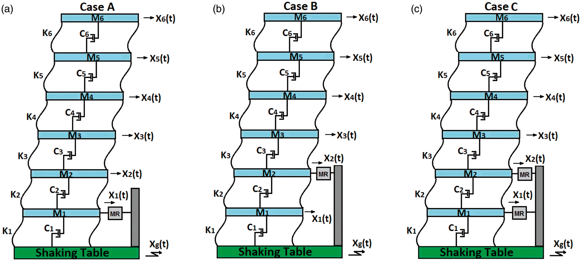
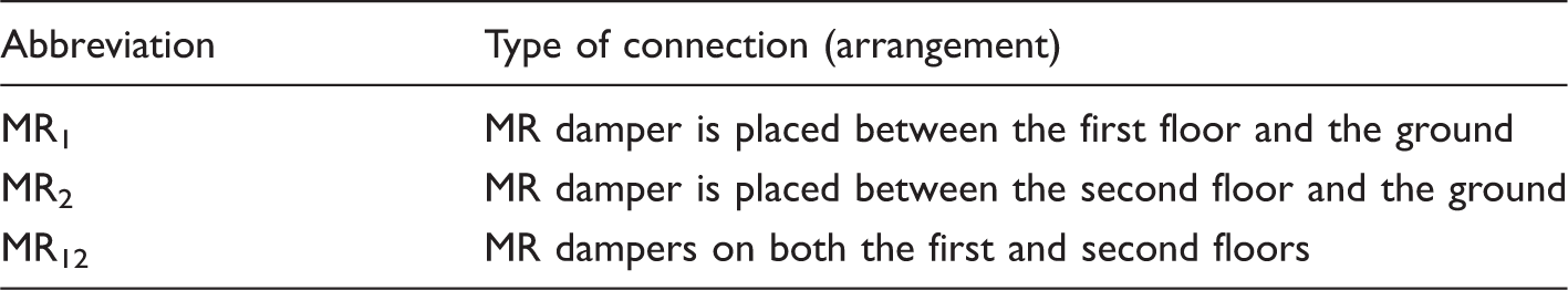
In this study, three different MR damper locations (arrangements) in a six-story steel frame structure are investigated, as shown in Figure 1. The three MR damper arrangements that are examined are listed below:
Case A: An MR damper is installed between the first floor and the ground (MR1). Case B: An MR damper is installed between the second floor and the ground (MR2). Case C: Two MR dampers are used. The first MR damper is installed between the first floor and the ground, and the second MR damper is installed between the second floor and the ground (MR12). Three cases of the MR damper locations. (a) The MR damper is located between the first floor and the ground, (b) the MR damper is located between the second floor and the ground, and (c) the MR damper is located on both the first and second floors. MR: magnetorheological.
The mathematical movement of the building models shown in Figure 1 can be given as


If the MR damper is placed between the second floor and the ground

If the MR damper is on both the first and second floors,

The seismic input vector is
Robust control design
The results of the previous section allow for the creation of a model that is used in the control design. In this section, a robust controller is designed based on the reduced-order model (ROM) and then applied to the full-order model (FOM). A mixed sensitivity problem is considered for the control design. The performance of the designed controller is presented, and the semiactive controller implementation rule is defined.
Identification of the system and model reduction
In most cases, controlling the lower modes effectively reduces the amplitude of the structural system. In particular, the effects of the lower modes are greater than the higher modes in the vibrations of flexible systems, such as elastic rotors, beams, and high-rise buildings. 26 Therefore, controlling only the lower modes is important and sufficient to mitigate vibration. Moreover, such flexible systems are modeled with many DOFs. The controller can be designed based on these FOMs. Nevertheless, it is difficult to design and implement control using FOMs when the system model is too large, especially in experimental studies and real applications. Therefore, using ROMs that capture the dominant characteristics of the system represents a meaningful alternative for control design and implementation.
In this study, a modal approach is chosen to reduce the order of the model. An H∞ controller is designed based on this ROM and is applied to the FOM. In this approach, the higher modes are truncated, and the lower modes are considered in the model used to control the design. Neglected system dynamics occur in the reduction procedure. All of these dynamics induce system uncertainties. Considering again the structural system that was modeled in the previous section, the FOM of the system in physical coordinates can be written in the state-space model as follows


Here, the Cy1 and Cy2 vectors represent the locations of the measurements and are defined as

The system matrix can be designed as

For the model order reduction, the system must be transformed from the physical space to the modal space. Transformation from the physical space to the modal space can be performed using the following operator

Using this modal coordinate transformation vector, the equation in modal coordinates can be written as

When structural control is considered, controlling the first two modes provide good results for the earthquake hazard mitigation of structural systems and reduces the amplitudes. Therefore, the ROM is formed using the first two modes of the full-order system. Thus, the ROM is defined in the form of


Controller design
If the controlled variable converges to a value determined by the stability condition of the system, it is termed regulator type. In this study, a regulator-type control system is considered. Thus, there is no need to follow the reference input while controlling the system. In control theory, the regulator problem is the design of the controller such that norm of the closed-loop transfer function is minimized and the closed-loop system is stable.
The parametric uncertainties are defined as differences between real values and the parameters of the mathematical model.
27
Systems models affected by parametric uncertainties reduce the control system performance.
28
The robustness of the control strategies is studied by many different applications considering the sensitivity of the control system to parametric errors and measurement noise added to the system.11,26–32 Many dynamic destructive effects, such as high-frequency dynamics, which cannot be modeled and which form in different parts of the system, can be evaluated in a single block, such as “Δ.” These uncertainties are called “nonstructural uncertainties.” In linear time-invariant systems, Δ represents an unknown transfer function. Differences between real systems and dynamic models are modeled as follows

The primary point of H∞ control design is stability of the feedback control system against unknown additive uncertainties. Considering the block diagram of the control system shown in Figure 2, the two primary transfer functions in this control system are S(s) and T(s). S(s) is defined as the sensitivity transfer function, and T(s) is the complementary sensitivity transfer function. Generally, T(s) is the primary transfer function for the stability of a closed-loop system. When T(s) and Δt(s) are considered stable, using a WT filter and provided that the upper limit of Δt(s) satisfies
Augmented system structure.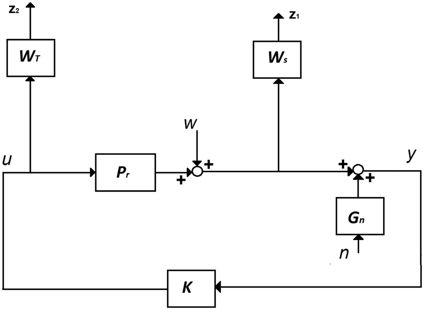


The second aim of the H∞ controller is to improve the performance of the feedback control system. The problem regarding improving the response performance is how to attenuate the influence of the disturbance w on the output y of the plant. This issue is related to minimization while subjected to the condition of stability of the closed-loop system. The H∞ norm condition can be written as


Selection of frequency shaping filters
An important step in H∞ control is to determine the frequency shape filters. Additive uncertainty is used to select WT. A filter should cover the uncertainty to provide robust stability. Moreover, the objective of the control, which is the control of the first two modes, should be considered. Furthermore, considering the spillover effect, the controller should suppress the first two modes without exciting the truncated modes. In this manner, frequency shape filters take the following form

Controller application in semiactive system
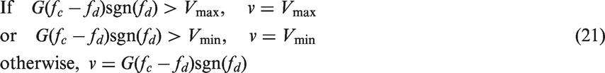
The MR damper’s voltage should vary to ensure that the necessary power can be produced in the system. A continuous state function is used to achieve these changes in voltage. The voltage of the MR damper is selected as follows33,34
Experimental performance analysis and results
Shaking table experiments are conducted in the Machine Theory, System Dynamics and Control Laboratory of Yildiz Technical University to test the designed control algorithms. Experimental verification is completed using a six-story steel frame structure, as shown in Figure 3. This type of steel frame structure model is generally used in experimental studies in the literature. Each floor of the structural model is formed by connecting sheet metal using screws. The weight of each floor is approximately 107.5 kg. Eight bars between floors, which represent columns, are made of spring steel. Each bar is 3 mm thick and 50 mm wide. The distance between the floors is 250 mm, and the floors and bars are connected using screws.
Experimental view of the structural model (MR12). MR: magnetorheological.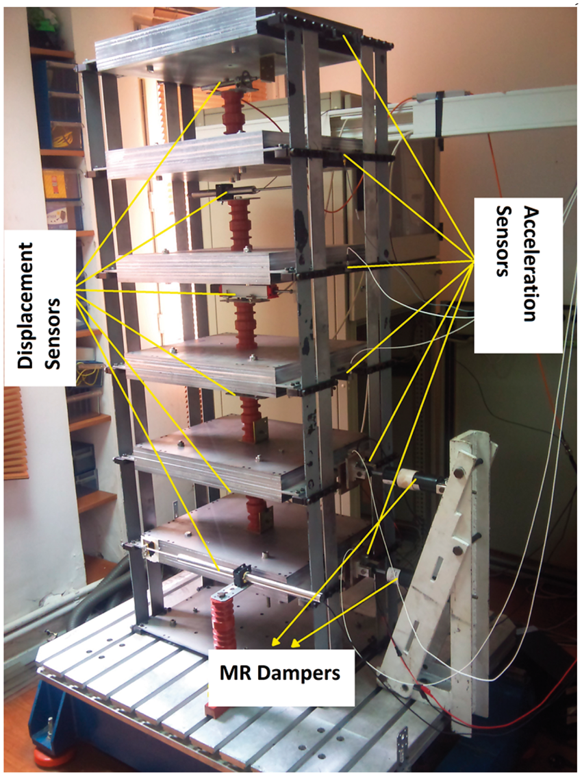
Sensors of different brands and types are used as the measurement equipment. A schematic view of the experimental system (for MR12) is shown in Figure 4. A driving servo-motor system of the shaking table and the application of the designed controllers in the system are conducted using a dSpace ACE Kit 1103. A 12-channel NetdB signal analyzer is used to process the acceleration signals. In this experiment, the displacement and acceleration of each floor are measured. One Waycon-branded linear variable position sensor (LVDT), one Solartron LVDT, one Burster LVDT, and three Opkon-branded resistive linear position sensors are used to measure the displacement. Two Brüel&Kjaer accelerometers and four Dytran accelerometers are used to measure the acceleration. Three types of RD-8041 MR dampers are installed in the building model, denoted as MR1, MR2, and MR12 and summarized in Table 1.
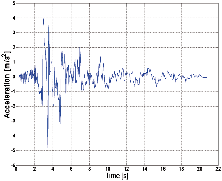
Schema of experimental system (MR12). MR: magnetorheological. Abbreviations of MR dampers and placement types. MR: magnetorheological. East–West component of the Erzincan earthquake.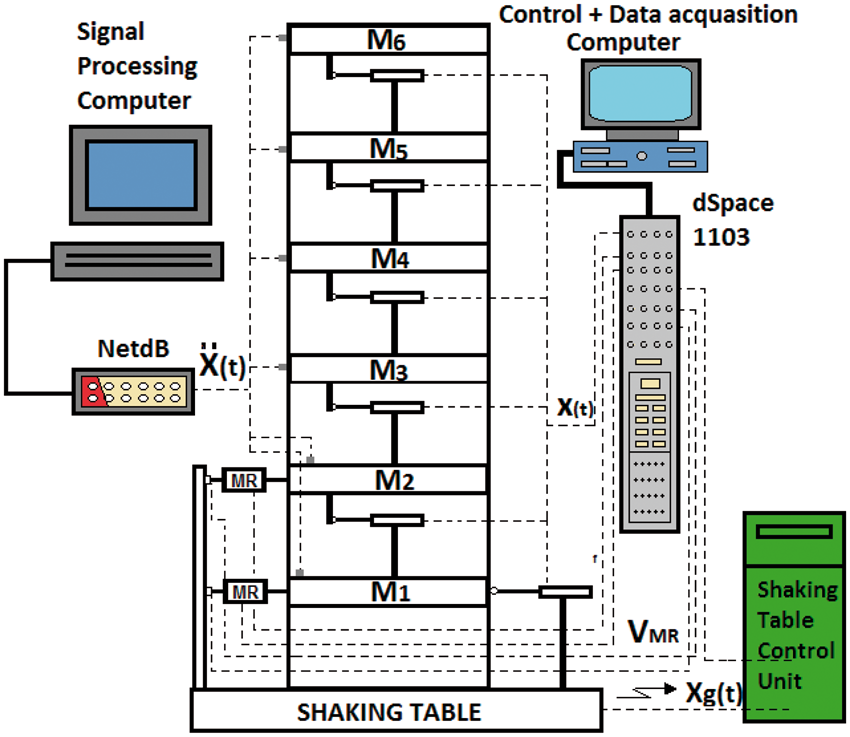
The force formed by the MR damper is measured using Brüel&Kjaer and Dytran force sensors. The processing of the displacement and the force data is conducted using dSpace ACE Kit 1103. Two adjustable power generators are used to supply the displacement sensors. One computer is used to data process the acceleration data, and another computer is used to drive the shaking table and to control and process the data by communicating with dSpace.
Determining the model parameters of the experimental system
The parameters are determined using empirical expressions in structural dynamics. The mass value of system for each floor is 107.5, and the mass matrix is
Application of the H∞ controller
The H∞ controller designed for a 6-DOF semiactive structural system, as described in “Robust control design” section, is applied to the structural models in Figure 1. A 0.5-scale Erzincan earthquake is considered as the seismic excitation (see Figure 5).
Three different installation layouts (connection types) are studied. Abbreviations for these scenarios are shown in Table 1. The output vector in equation (4) of the displacement feedback on the first floor for MR1 is
The last frequency values to be controlled and the first frequency values, which are not controlled, are used to adjust the frequencies of the WT filter in equation (20). The last mode frequency to be controlled in the numerator is considered as the next mode frequency, which is not controlled in the denominator. The aim is that control gain is acquired in the frequency area to control the first two modes to sustain robust stability and such that it does not simulate any other modes, which are not controlled. The coefficients of the controllers are kw
= 0.4, ξnm
= 0.65, ξdm
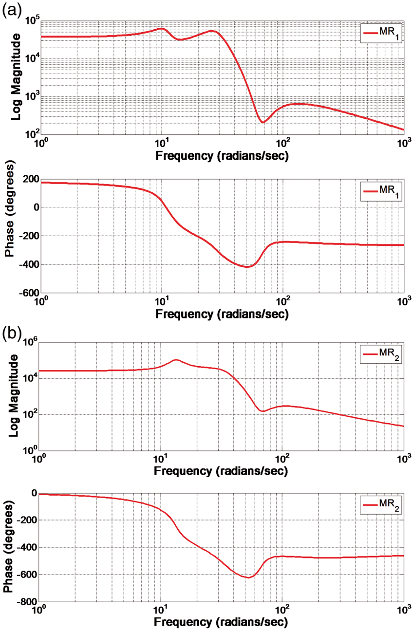
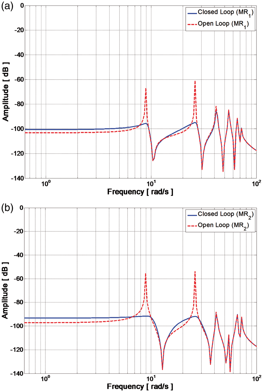
= 0.15, ωnm = 43, and ωdm = 66. The H∞ controller is applied to the experimental structural model using the MR damper. The first two modes are the reduced forms of the 6-DOF systems for the H∞ controller. The ROM and FOM are illustrated in Figure 6, which shows that the first two modes of both models match. Therefore, the first two modes of the ROM present the same characteristics as the first two modes of the FOM. The H∞ control is designed using MATLAB. The frequency response of the H∞ control is shown in Figure 7. To suppress the low-frequency region, the controller has the highest gain around the range of the first two modes. Accordingly, to avoid the spillover effect, the lowest gain is provided around the truncated modes, in which the control effect is not expected. Finally, the open- and closed-loop responses of both the FOM and ROM are shown in Figure 8. The figure shows that the controllers achieve good performance and reduce the frequency range of the controlled modes without exciting the truncated modes. The MR1 and MR2 controllers are used together for the MR12 controller.
FOM and ROM: (a) MR1 and (b) MR2. FOM: full-order model; MR: magnetorheological. ROM: reduced-order model. Controller frequency response: (a) MR1 and (b) MR2. MR: magnetorheological. Open- and closed-loop responses of the system: (a) MR1 and (b) MR2. MR: magnetorheological.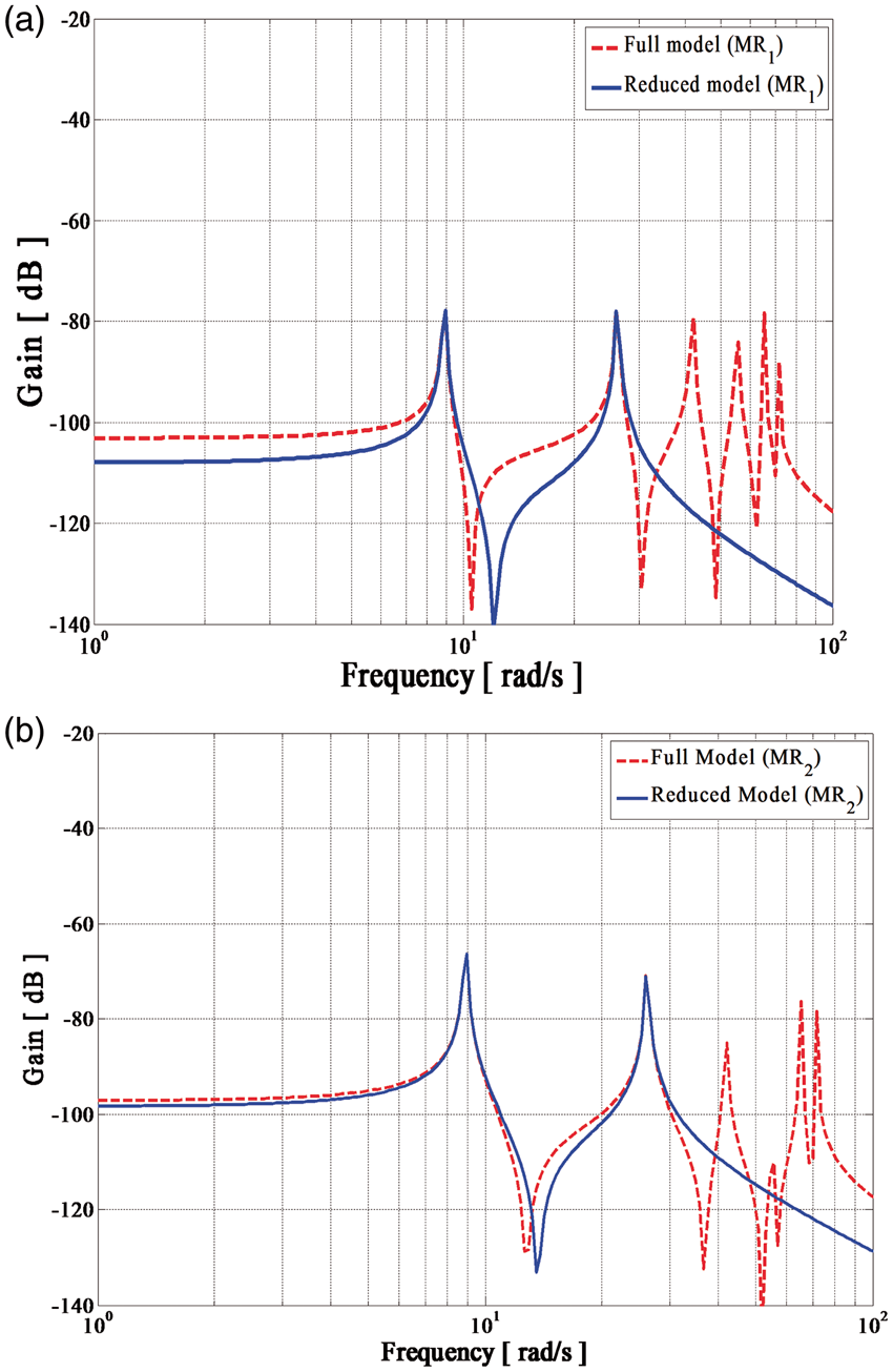
Here, the amplitude values indicate the maximum value of the vibration mode of the system for the passive and controller cases.
Displacement responses
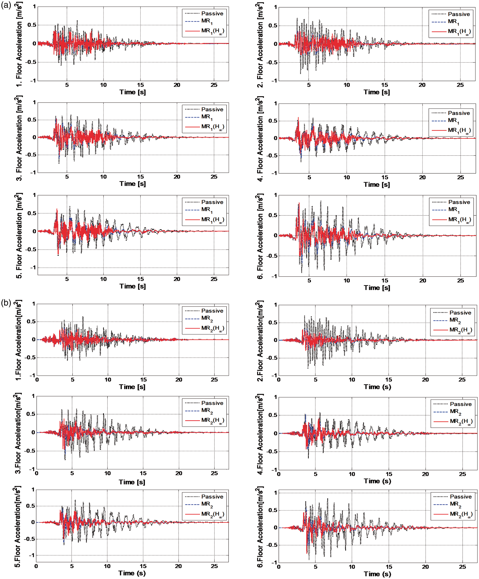
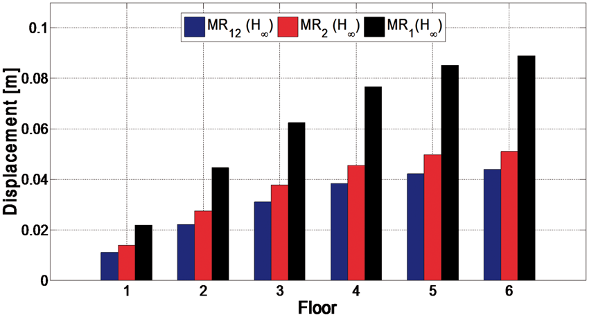
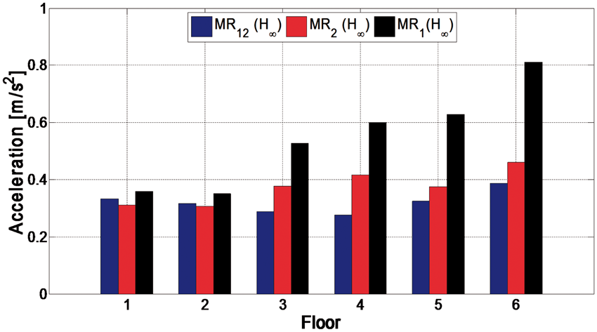
The time responses for the situations of all combinations of the MR damper’s layout (MR1, MR2, and MR12) are shown in Figures 9 to 12. The displacements of the MR1, MR2, and MR12 situations are compared in Figures 9 and 11. The acceleration responses are illustrated in Figures 10 and 12. The passive (MR damper disconnected), passive with MR damper (MR damper connected), and H∞ controlled situations are compared to determine the performance of the controller. The cases in which the MR damper is only on the first floor (MR1), on the second floor (MR2), and on both the first and second floors (MR12) are examined. The performance of the controller is compared with the cases in which the MR damper is not connected and the MR damper is connected but uncontrolled. “MR1” denotes that the MR damper is connected to the first floor and that there is no voltage. The case in which the MR damper is connected and controlled case is denoted as “MR1 (H∞).” The “MR2 (H∞)” and “MR12 (H∞)” represent for the situations in which the MR damper is on the second floor and there is no voltage and in which the MR damper is on second floor and controlled, respectively. “MR12” and “MR12 (H∞)” are typified in the same manner. The displacement responses of all floors are shown in Figure 9. Comparisons of the passive, uncontrolled, and controlled cases for all combinations of the MR damper’s layout are depicted in Figure 9(a) to (c), respectively. The connection of the MR damper reduces the vibration of each floor. The amplitudes of the displacement in both situations corresponding to the passive MR and the MR with the controller are lower than the displacement amplitude in the situation corresponding to the passive system without the MR damper. Furthermore, implementation of the robust controller improves the vibration reduction performance of the MR damper. The MR damper with the robust controllers is better than the MR-uncontrolled cases. The acceleration responses of each floor for all combinations of the MR damper layout are shown in Figure 10. The connection of the MR damper and the application of the robust controller improve the acceleration responses of each floor. As shown in Figures 11 and 12, the controlled cases for all situations are compared. The maximum displacement responses are compared in Figure 11. The best performance is achieved by MR12 (H∞), in which an MR damper is on both the first and second floors and is commanded by the H∞ controller. Figure 12 compares the maximum acceleration responses. MR12 (H∞) again exhibits the best performance. Generally, implementation of the controller reduces the maximum absolute values of the accelerations. However, some of the maximum absolute values for the controlled cases are greater than the MR damper-passive cases.
Displacements of all floors for the combinations of the MR damper layout: (a) MR1, (b) MR2, and (c) MR12. MR: magnetorheological. Accelerations of all floors for the combinations of the MR damper layout: (a) MR1, (b) MR2, and (c) MR12. MR: magnetorheological. Comparison of the maximum displacements of all floors for the controlled cases (MR1(H∞), MR2(H∞), and MR12(H∞)). MR: magnetorheological. Comparison of the maximum accelerations of all floors for the controlled cases (MR1(H∞), MR2(H∞), and MR12(H∞)). MR: magnetorheological.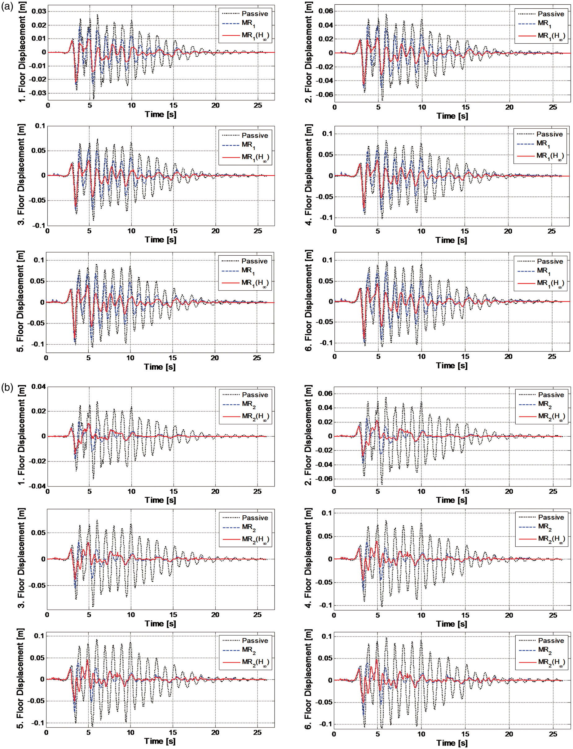
Assessment of the structural vibration performance
To evaluate the test results in detail, the performance indices formed by Ohtori et al.
35
are used as follows
4
The maximum interstory drift ratio of the uncontrolled structure. distance between floors, displacement between floors, absolute acceleration without the controller.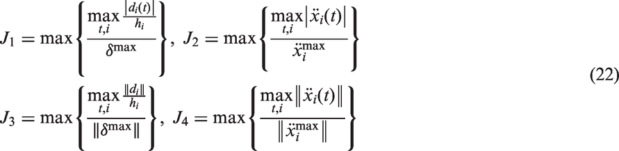
Assessment of the controller according to the performance indices.
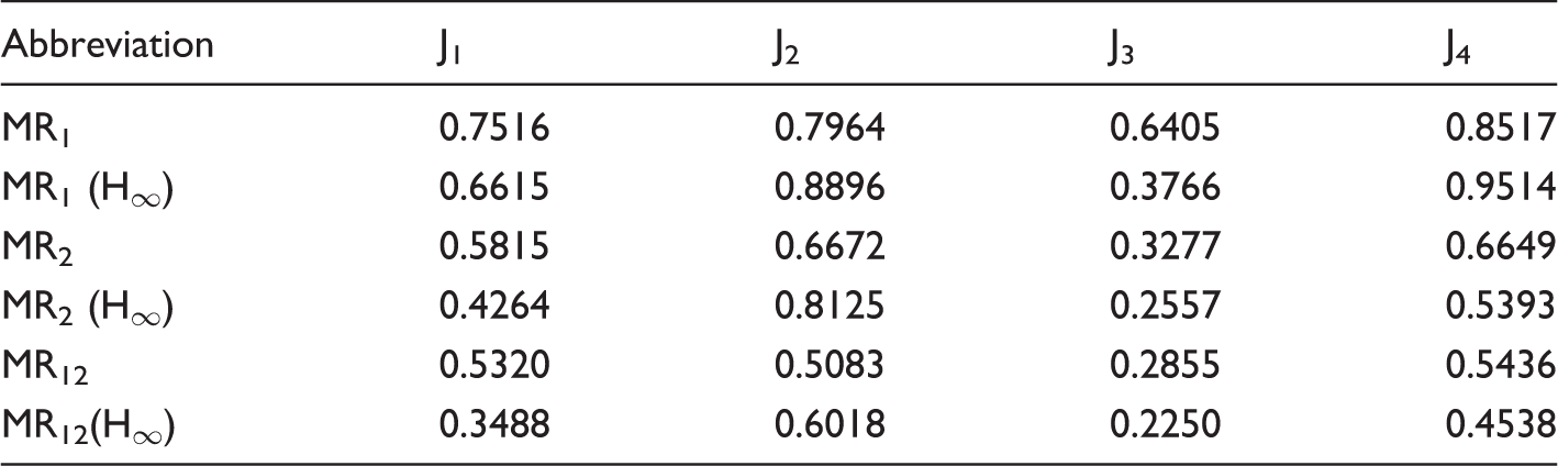
MR: magnetorheological.
Thus, the system amplitude decreases for a passive MR damper in the system. When the passive cases with the MR damper are compared, the best performance is obtained for the MR12 case in which the MR damper is placed on both the first and second floors. When the passive situations and situations with the controller are compared, situations with the controller decrease the vibration amplitudes more effectively than in the passive cases. Similarly, when the three connection types are compared, the best performance is acquired for the MR12 situation, as shown in Table 2. The second performance index is based on the maximum acceleration value. The J2 performance index is less than 1 for the MR1, MR2, and MR12 situations. Thus, for the passive MR damper system, the acceleration of the system also decreases. When we compare the passive situations, the best performance is achieved for the MR12 situation in which MR damper is placed on both the first and second floors. When the situations with the controller and passive situations are compared, MR12 has the best performance. Although situations with the controller compress the displacement of vibrations, the acceleration response worsens in situations with the controller. This occurs because the controlled voltage while the MR damper is functioning occasionally locks the MR damper, and thus, the acceleration values of the floor on which the MR damper is placed increase. The third performance index is based on the maximum value of the displacement norm. Again, the best performance index is achieved by MR12 (H∞). The fourth performance is based on the maximum value of the acceleration norm. The performances of MR12 (H∞) and MR2 (H∞) recovered. The best performance is achieved by MR12 (H∞). As this performance index involves all acceleration values, the fact that the values of MR2 (H∞) and MR12 (H∞) are better than the passive values indicates that the controllers decrease the total acceleration values even though they fail regarding the maximum acceleration values.
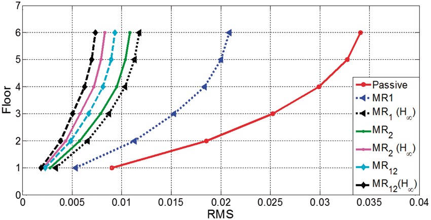
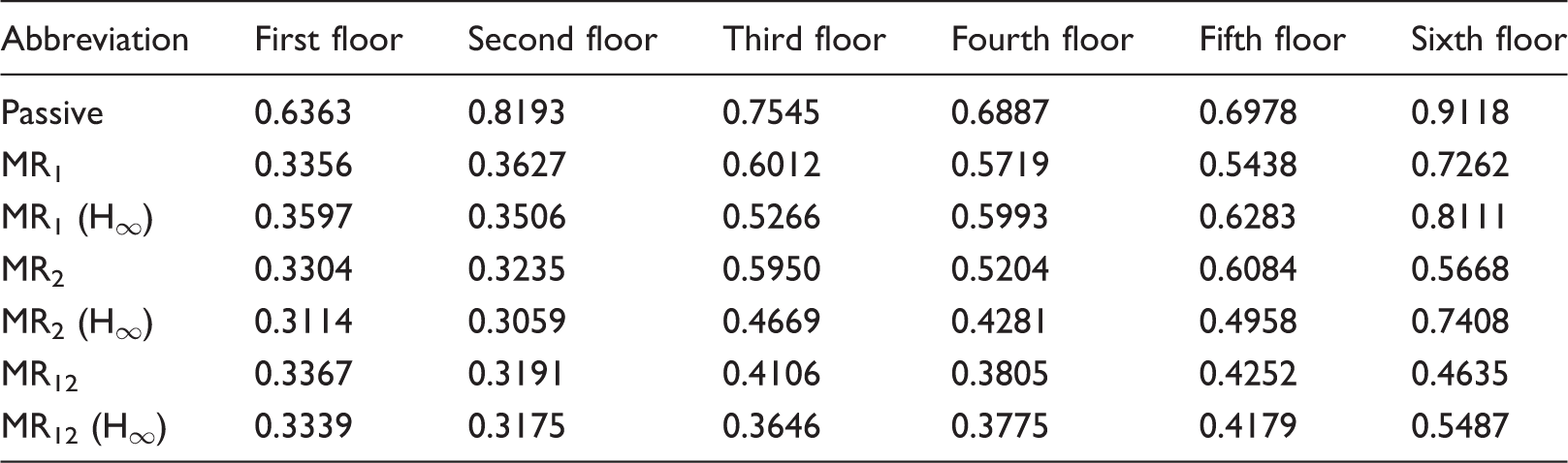
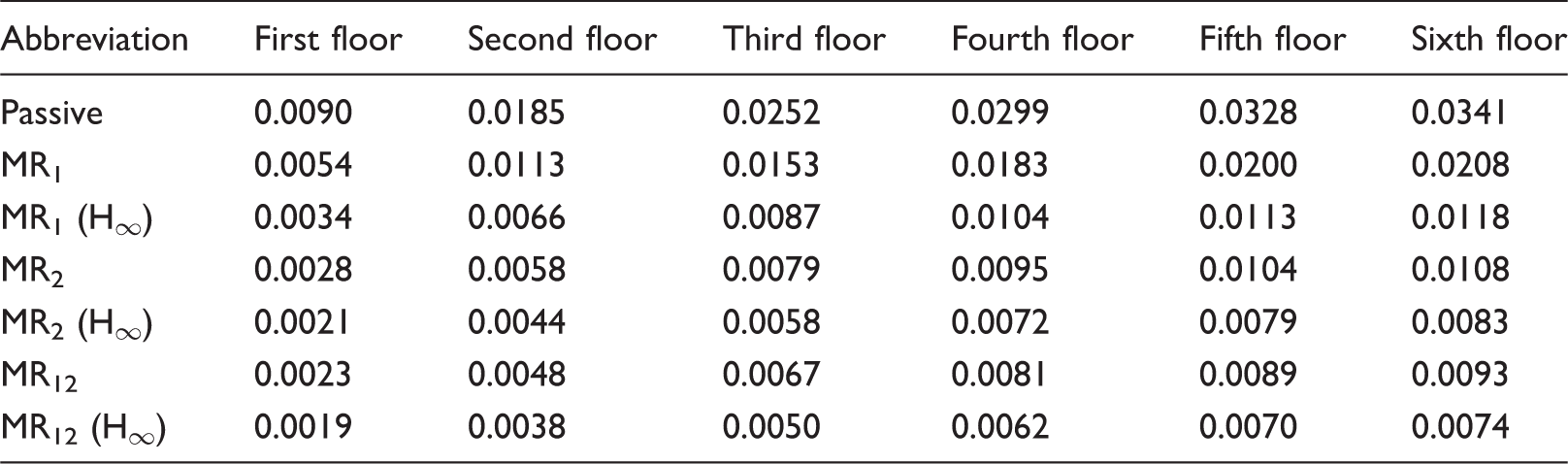
The maximum displacement values of each floor are shown in Figure 13. The passive case, which corresponds to when the MR damper is not connected to the structure, performs worse than the other cases. The displacement values of each floor for the passive case are greater than both the uncontrolled and controlled cases. The connection of the MR damper to the structure reduces the displacement of all floors. In addition, all of the H∞-controlled cases perform well compared to cases when the MR damper is connected but not controlled. For example, the maximum displacement values of each floor in the MR1 (H∞) case are smaller than the MR1 uncontrolled case. Similarly, the application of the robust controller reduces the maximum displacement values in both the MR2 and MR12 cases. The RMS values of each floor are shown in Figure 14. The RMS values of the passive case are larger than those of the other cases. Again, connecting the MR damper reduces the RMS values. In addition, the MR1(H∞), MR2(H∞), and MR12(H∞) cases perform well in terms of reducing the vibrations on each floor compared to the uncontrolled cases. Thus, the H∞ controller exhibits good performance in reducing the displacement of all floors, and it exhibits the best performance for the MR12 situation. The maximum displacement values shown in Figure 13 and the RMS values shown in Figure 14 verify the above summarized performance analysis. The absolute maximum values of the accelerations are given in Table 3. The absolute maximum values of the accelerations for all combinations of the MR dampers are lower than those in the passive case. The RMS values are shown in Table 4. All of the absolute maximum values of the accelerations for all combinations of the MR dampers are lower than for the passive case. In general, implementation of the controller reduces the maximum absolute values of the accelerations. However, some of the maximum absolute values for the controlled cases are greater than the MR damper-passive cases.
Maximum displacement values of the floors. RMS displacement values of the floors. RMS: Root mean square. Absolute maximum acceleration values for all floors. MR: magnetorheological. RMS values for all floors. MR: magnetorheological; RMS: Root mean square.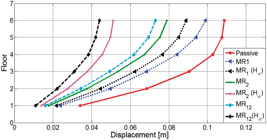
Conclusions
In this study, a H∞ robust controller is designed to command MR damper voltage by placing an MR damper on different floors to reduce building vibrations during earthquakes. The designed controller is experimentally tested in the laboratory using a shaking table and a six-story structural model. The performances of the controller and MR damper are investigated. Comparisons are made among cases when the MR damper is not connected, passive, and controlled with H∞. Additionally, we study how the building reacts when the MR damper is placed in various combinations. The evaluations are based on the displacement and acceleration responses and the performance indices. Moreover, the maximum displacement values and RMS values of each story are considered. When the passive damper situations are considered, the structural system amplitudes decreased compared to the case without the MR damper for all three combinations. The arrangement of the MR damper in which one end is connected to the ground is effective in reducing the vibration amplitudes. In addition, the MR damper connected between the second floor and the ground is more effective than the damper connected between the first floor and the ground. However, the best combination of MR dampers is the connection between both the first floor and the ground and between the second floor and the ground. Furthermore, the designed controller clearly improves the system performance. The best performance is acquired for the MR12 (H∞) situation, in which an MR damper is located on both the first and second floors and the dampers are commanded by the H∞ controller. In one MR damper case, the MR damper arrangement which is connected between ground and second floor reduces the vibration amplitudes more than the MR damper arrangement which is connected between ground and first floor. In future studies, the case for which the MR damper is connected to the system between the first and second floors will be examined and compared to the previous cases.
Footnotes
Declaration of conflicting interests
The author(s) declared no potential conflicts of interest with respect to the research, authorship, and/or publication of this article.
Funding
The author(s) disclosed receipt of the following financial support for the research, authorship, and/or publication of this article: This study was supported by The Scientific and Technological research council of Turkey (TUBITAK) under grant no. 213M664.