
Abstract
With ongoing advances in deep oil and gas exploration, the drilling depth of large-borehole sections has steadily increased. Consequently, the geological and engineering conditions encountered during drilling have become increasingly complex, often leading to poor bit performance and high drilling costs. To enhance the rate of penetration (ROP) in hard-to-drill formations, a series of experiments and numerical simulations were carried out under in-situ temperature and pressure conditions. The mechanism of difficult drilling was revealed: under in-situ conditions, large-diameter drill bits are subjected to severe vibration, while rock strength and plasticity increase significantly, thereby restricting cutter penetration into the formation and markedly reducing rock-breaking efficiency. Considering borehole size and in-situ conditions, a discrete element interaction model of rock and shaped cutters was established, with model-experiment deviations within 5.5%. Based on this model, the rock-breaking mechanism of shaped cutters was clarified, and key design parameters of polycrystalline diamond compact (PDC) bits—such as cutter geometry (triangular prismatic cutter), cutter diameter (16 mm), and back rake angle (15°-25°)—were identified. This study provides insights into the rock-breaking process and offers technical support for improving ROP in large-borehole drilling of the challenging formations under in-situ conditions.
Keywords
Introduction
With the recent advancement of deep oil and gas development, the drilling depth of large-borehole sections (Wellbores with a diameter greater than 333.4 mm in this study) has increased substantially, accompanied by escalating drilling challenges. Using the S, Z, and X strata in a block of the Sichuan Basin as examples, these formations are characterized by pronounced heterogeneity, high strength, and strong abrasiveness. In large-borehole sections, however, the available rock-breaking energy is insufficient, thereby limiting effective bit penetration into the formation. Furthermore, severe bit vibrations, rapid wear, and premature failures are frequently observed. Notably, in the Z stratum, the rate of penetration is typically below 2 m/h, and single-bit footage is typically below 100 m, severely constraining the economical and efficient development of oil and gas resources in the region.
There are abundant personalized drill bits for deep, challenging formations. Peytchev et al. (2013) designed a new bit with six blades and 13 mm cutters for strong abrasive formation (6 in section) in the Raageshwari oilfield in India, which resulted in a 47% reduction in drilling time. Maouche et al. (2014) combined the new PDC cutter technology with the new multi-stage cutting structure force balance for the hard abrasive formation (8-3/8 in section) in Oman and created the longest drilling record in the hard sandstone formation in Oman. Aiming at strong abrasiveness, short bit life, and slow drilling speed in the sandstone-shale interlayer (8-1/2 in section), Edge et al. (2018) designed a new PDC bit with 7 blades, 16 mm cutters, and shaped cutters. The field drilling speed was greatly improved. Chen et al. (2024) designed a customized PDC bit with a hybrid cutter arrangement for conglomerate formation. Compared with adjacent wells, the average ROP of this bit increased by 7.88%-63.37%. Huang et al. (2024) designed a circumferential groove PDC bit for deep formation, incorporating a circumferential annular groove on the bit body to enhance the bit's penetration ability and rock-breaking efficiency. Field applications showed significant increases in both ROP and footage. The world's major drill bit companies also have their own series of personalized drill bits for deep, complex formations. However, there are relatively few studies on efficient drill bits and related theories for large-borehole sections at present; therefore, conducting this research is of great significance.
In recent years, many scholars have carried out research on the influence of temperature or pressure on rock properties and rock-breaking mechanisms. Zhang et al. (2021) explored the effect of temperature on the mechanical properties of granite, finding that the strength and modulus of elasticity of the rock decreased with increasing temperature. Meng et al. (2005) found that the stiffness and strength of rock increase significantly with the rise of confining pressure. Li et al. (2021) carried out compressive tests on sandstones under different confining pressures. The results show that the increasing confining pressure tended to strengthen the majority of rock mechanical parameters. The Kansas State University has carried out rock-breaking experiments and simulation studies under normal pressure and high pressure. It is found that the high hydrostatic pressure will produce long debris, which increases the rock-breaking difficulty and reduces the drilling speed (Kaikay and Lei, 2005; Lei and Kaitkay, 2003). Rajabov et al. (2012) carried out cutting experiments on different kinds of rocks under different pressures. The results show that the mechanical specific energy under confining pressure is significantly higher than that without confining pressure. Liu et al. (2018) carried out rock-breaking simulations under high pressure and found that the high pressure would lead to an increase in the critical cutting depth of the ductile-brittle failure mode transition of rock. Currently, there are many studies on the rock-breaking mechanism of hot dry rock under high temperature (Dai et al., 2025; Yang et al., 2024). But a few experiments are using shaped cutters for abrasive sandstone under in-situ conditions. Moreover, numerical simulation is an important method to investigate the rock failure process and to optimize the design of the drill bit. In previous studies, the finite element method (FEM) has been widely used to research rock breaking. The continuous interpolation function used in this method makes it difficult to characterize the disconnected contact characteristics at the fracture junction; thus, the discrete element method is applied in this paper (Potyondy, 2015; Potyondy and Cundall, 2004; Pryhorovska et al., 2015; Rojek et al., 2011; Wang and Tonon, 2009).
Experiments
Rock mechanics experiments
The Sichuan Basin is one of China's key natural gas-producing regions and contains abundant reserves. However, drilling large-borehole sections in this basin presents significant challenges, including severe bit vibration, short bit life, and low rates of penetration (ROP). To investigate these issues, this study focuses on outcrop samples from challenging formations in large-borehole sections of the Sichuan Basin. The outcrops from the S, Z, and X strata were collected, as shown in Figure 1.

The outcrops of the large borehole section in the Sichuan basin. (a) S stratum, (b) Z stratum, and (c) X stratum.
The confining pressure and in-situ temperature of each stratum were estimated based on geological parameters. The values are approximately 20 MPa (70°C) for the S stratum, 30 MPa (85°C) for the Z stratum, and 40 MPa (100°C) for the X stratum. For the consistency of the experiments, all triaxial compression tests were conducted at 100°C, while uniaxial compression tests (with a confining pressure of 0 MPa) were performed at room temperature to represent the atmospheric environment. Figure 2 presents the rock mechanical curves of sandstone from the different strata under in-situ conditions.
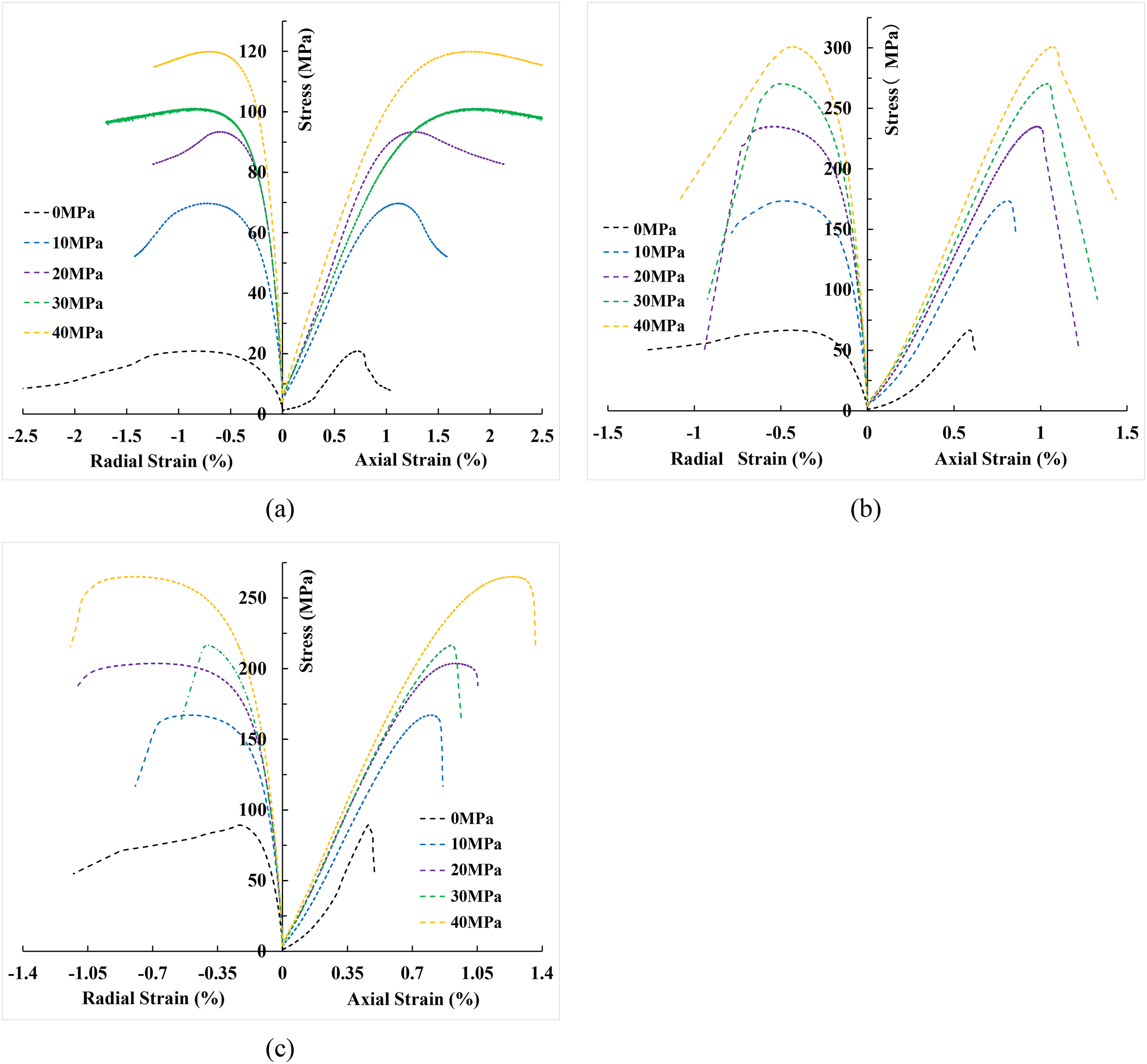
The differential stress-strain curves of the sandstone (Liu et al., 2022, 2023). (a) S Stratum, (b) Z Stratum, and (c) X Stratum.
As shown in Figure 2, the peak stresses of the S, Z, and X strata were 20.84 MPa, 66.64 MPa, and 89.35 MPa, respectively, under atmospheric conditions. Under in-situ conditions, these values increased to 93.32 MPa, 270.44 MPa, and 264.99 MPa, representing increases of 347.8%, 305.8%, and 196.6%. These results clearly indicate that sandstone strength increases sharply with confining pressure.
Based on these experimental findings and the stress-strain curves, the mechanism underlying difficult drilling under in-situ conditions can be clarified. At atmospheric pressure, the rock is relatively weak and brittle, enabling the cutter to achieve a greater depth of cut (DOC) at the same weight on bit (WOB), thereby promoting volumetric fragmentation during cutting. In contrast, under in-situ pressure, rock strength increases markedly, restricting cutter penetration. As a result, DOC decreases, drilling speed is reduced, rock-breaking efficiency declines, and the cutting process shifts from volumetric fragmentation to grinding. Furthermore, the elevated in-situ pressure significantly enhances rock plasticity, further suppressing volumetric crushing.
Rock-breaking experiments of shaped cutters
Clarifying the rock-breaking mechanisms and performance differences of shaped cutters in difficult-to-drill formations is essential for supporting efficient and customized bit design. To this end, in situ rock-breaking tests of shaped cutters were conducted. The micro-PDC bits developed with the shaped cutters are shown in Figure 3.
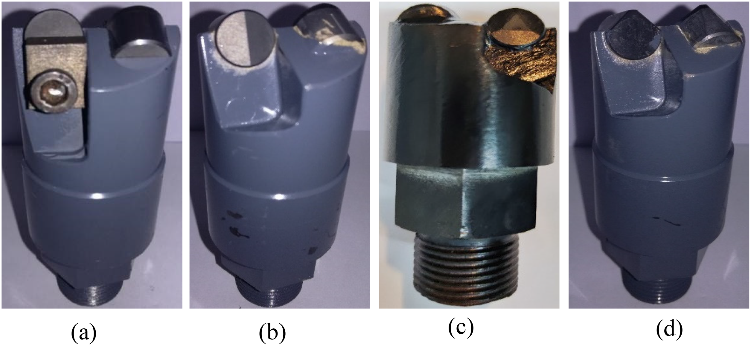
The micro PDC bits with the shaped cutters. (a) Cylindrical cutter, (b) ridge cutter, (c) triangular prismatic cutter, and (d) V-cutter.
The rock-breaking experiments were performed using a high-temperature and high-pressure rock drillability test system (Figure 4), which consists of a core clamping system, a stratum pressure and temperature system, a depth measurement system, an automatic control system, and a data acquisition system. The test procedure was as follows: (i) activate the power supply and air compressor, and check hydraulic medium sufficiency; (ii) install the rock sample in the test chamber and clamp the micro-bit onto the rotary system; (iii) apply boundary conditions such as confining pressure; (iv) start the measurement and control system to collect data; (v) stop bit rotation and data acquisition; and (vi) release pressure, remove the rock sample, and clean debris. Given the extremely high strength of the Z stratum, in-situ rock-breaking experiments were carried out using samples from this formation. Experiments were conducted under a confining pressure of 40 MPa and rotational speeds of 50, 80, and 110 RPM. With the WOB and drilling time kept constant, the drilling depths were determined, as shown in Figure 5.

The rock drillability test system.

The drilling depth of the shaped cutters.
The experimental results demonstrate that the drilling depths of the cylindrical cutter, V-cutter, triangular prismatic cutter, and ridge cutter all increase with rotational speed. The mechanism is that, under otherwise identical conditions, the increase in circumferential cutting velocity leads to a greater number of cutter-rock interactions per unit time. This, in turn, enhances stress concentration through elevated local strain rates and dynamic impacts, thereby promoting crack initiation and propagation and ultimately improving the rate of penetration. Due to geometric differences, each cutter type exhibits a distinct sensitivity to rotational speed. Among them, the V-cutter achieved the greatest drilling depth. This can be attributed to its “point-line” contact mode, which generates stronger stress concentrations and enables more efficient penetration into the formation under the same WOB. The triangular prismatic cutter produced drilling depth lower than that of the V-cutter but markedly higher than that of the cylindrical and ridge cutter, indicating superior rock-breaking efficiency in this formation. In contrast, the cylindrical cutter and ridge cutter yielded comparable drilling depths: the former performed slightly better at low rotational speeds, whereas the latter surpassed it at medium to high speeds. Overall, rotary drilling tests of the micro PDC bits with the shaped cutters suggest that the triangular prismatic cutter and V-cutter exhibit high drilling speed in the target formation. Their performance will be further validated through numerical simulations in subsequent sections.
Model establishment and verification
Method explanation and parameter calibration
During the rapid development of the discrete element method, most previous studies have been based on the traditional bonded-particle model (BPM) or the parallel bond model (PBM). However, these conventional models generally produce a ratio of compressive strength to tensile strength in numerical simulations that is significantly lower than laboratory test results. To address this issue, the flat-joint model (FJM) was adopted (Potyondy, 2012). In this model, a set of small, flat, bonded facets is automatically created at each particle contact, representing an interface capable of transmitting both normal and shear forces as well as bending and twisting moments. The interface behaves as a deformable link, while the connection to the rigid particles remains intact. Once the stress or displacement exceeds the strength criterion, the interface breaks and the contact is removed. Compared with conventional models, the FJM produces denser contacts with an interlocking effect. As a result, the simulated uniaxial compressive strength increases more significantly than the tensile strength, yielding a higher compressive-to-tensile strength ratio (Scholtès and Donzé, 2013).
The iterative procedure that Bahaaddini and Alidaryan suggested was utilized in this investigation to calibrate the target stratum's microscopic properties (Alidaryan et al., 2023; Bahaaddini et al., 2019). The tests of Brazilian splitting, Triaxial compression, and Uniaxial compression were used for calibration. The algorithm creates a container, which is subsequently filled with randomly distributed particles with a regularly distributed particle diameter. Lastly, particle-particle contacts that are smaller than or equal to the installation gap are subject to the flat-joint model. To avoid early cracks in the calibration of the elastic modulus and Poisson's ratio, choose the right number of flat-joint contacts and set the flat-joint cohesion to a higher value before the calibration. Next, the subsequent actions are implemented:
The tensile strength (σt) of the rock is calibrated by changing the flat-joint tensile strength in the Brazilian splitting test. The stiffness ratio (kn/ks) of the particles and the bond is adjusted in the Uniaxial compression experiment to reproduce Poisson's ratio (v) of the rock. In the previous iteration process, the macroscopic elastic modulus (E) is calibrated by changing the modulus (Ec) of the particles and the bond. The uniaxial compressive strength (σc) was then calibrated by changing the flat-joint cohesion (c). Finally, based on the results of the Triaxial compression experiments, the internal friction angle (
Given the large number of microscopic parameters involved in the calibration process, the assumption should be made to lessen the calibration's difficulty: Ec, kn/ks, and f in the particle parameters are consistent with those in the flat-joint contact parameters. Considering the simulation speed, the radius of the particles should not be too small. The minimum radius of the particles is 0.3 mm. The calibrated micro-parameters are presented in Table 1.
Calibrated micro-parameters of particles and flat-joint contacts.

The comparison between the experimental and numerical simulation results is presented in Figure 6. Overall, the two curves exhibit good agreement. Because the experimental rock samples were taken from outcrops, a compaction process occurs during the initial stage of compression. This accounts for the slight differences observed between the experimental and numerical curves in the early compaction stage. Furthermore, the fracture pattern obtained from the Brazilian splitting test was consistent with that predicted by the numerical simulation.

The comparison between experimental and numerical simulation results.
Additional comparisons between rock mechanics experiments and simulation results are presented in Figure 7 and Table 2. In Figure 7, the points on the horizontal axis represent σt. The point corresponding to a confining pressure of 0 MPa denotes σc, while the points at confining pressures greater than 0 MPa represent compressive strengths under various confining pressures. For additional clarification, the experimental values of the peak strength in Figure 7 were obtained by adding the peak differential stress (shown in Figure 2(b)) to the corresponding experimental confining pressure.

The comparison of the experiments and simulations.
The comparison between the simulation and the experiment.

From Table 2, it can be concluded that errors of σc, σt, E, and v are 0.98%, 1.03%, 5.20%, and 4.43% respectively. All errors are below 5.2%. In addition, it can be observed from Fig. 7 that under different confining pressures, the peak strengths obtained from experiments and numerical simulations are in excellent agreement. This indicates that the microparameters calibrated in this section have high accuracy and can be applied to subsequent studies.
Modeling
Based on the calibrated microscopic parameters, the shaped cutter was implemented in the discrete element program to construct the interaction model between the cutter and the difficult-to-drill stratum. As required, PDC bits or cutters of various sizes and geometries were first created using 3D modeling software. The cutter's 3D model was then converted into a file format recognizable by the procedure and imported into the numerically generated rock domain. To reduce computational effort, the coordinate system and units used in building the 3D model were kept consistent with the program. Finally, boundary conditions, including in-situ pressure and temperature, were applied to the model. Figure 8 illustrates the 3D model schematics of the shaped cutters, while Figure 9 presents the interaction model between the cutter and the target stratum under in-situ conditions.

The 3D model of the shaped cutters. (a) Cylindrical cutter, (b) V-cutter, (c) ridge cutter, and (d) triangular prismatic cutter.

The schematic diagram of the interaction model between the cutter and rock.
As shown in Figure 9, mud pressure was simulated by applying an equivalent force to the variable boundary surface. The program's servo function was used to control the sidewalls to impose confining pressure, while the bottom wall was fixed. This approach enables the simulation of transient heat conduction and storage within the particle model, as well as the stress evolution induced by thermal effects. In the program, thermal-mechanical coupling is implemented as a one-way process: temperature changes in the model induce volume changes, which in turn alter the internal stress state. Each particle is treated as a heat source in the thermo-mechanical computation, with heat flow transferred between particles, thereby affecting force distribution. Furthermore, the large borehole size of the target formation makes the bit more susceptible to bouncing during drilling, resulting in severe vibrations. To capture this effect, axial vibration was applied to the cutter through the servo control program during the cutting process. The application method involves referencing the axial vibration data of the drill bit during its actual operation in the large-borehole section, followed by imposing an axial velocity on the cutting teeth in the form of a sine function. Consequently, both the magnitude and direction of the axial velocity of the cutter vary at different moments throughout the simulation process. It should be noted that in reality, downhole drill bit vibrations are irregular. Therefore, this method of simulating vibrations cannot fully replicate the actual downhole vibration conditions. On this basis, the interaction model between the shaped cutter and the difficult-to-drill formation under in-situ conditions was established. Compared with conventional models, this model explicitly incorporates the effects of temperature, pressure, and vibration, thereby better reproducing actual downhole conditions.
Model validation
Prior to conducting the rock-breaking simulations, the cutter-rock interaction model must be validated. Many researchers obtain parameters such as cutting force or mechanical specific energy under various conditions through cutting experiments, either self-conducted or reported by others, and subsequently apply equivalent boundary conditions in rock-breaking simulations. The simulation outcomes are then compared with experimental data to assess the model's accuracy (Carrapatoso et al., 2014; Gonze and Tshibangu, 2017; Lei and Kaitkay, 2003; Luo et al., 2021; Mendoza et al., 2010; Zhu et al., 2017). In the present study, because the maximum formation temperature in the large-borehole section is approximately 100°C—with relatively small variation—its influence on rock-breaking efficiency is less significant than that of confining and hydrostatic pressures. Therefore, validation primarily focuses on reproducing the effects of hydrostatic and confining pressures. In the present study, the model was validated against experimental findings from the reference (Chen, 2021), and the rock microparameters were calibrated using the rock mechanics data contained therein. As shown in Table 3, the discrepancies between simulations and experiments are all within 2%.
The rock mechanics parameters of the simulation and experiment.

Based on the calibrated microscopic parameters, an interaction model between the cutter and rock under hydrostatic and confining pressures was established. For the cutter, the back rake angle was fixed at 10°, with the DOC maintained at 1 mm. The maximum and minimum horizontal in-situ stresses were fixed at 40 MPa and 30 MPa, respectively, with hydrostatic pressures of 0 MPa and 20 MPa. The cutting direction was oriented perpendicular to the maximum horizontal stress. A comparison of cutting forces between simulations and experiments is presented in Figure 10.

The cutting force between the simulations and experiments.
As shown in Figure 10, the simulation results agree well with the experimental data, with relative errors below 5.5%, indicating that the proposed model can effectively simulate the rock-cutting behavior of PDC cutters under in-situ conditions. Furthermore, the cutting force under hydrostatic pressure is notably higher than that observed without hydrostatic pressure. This increase may be attributed to the accumulation of cuttings in front of the cutting face under high hydrostatic pressure, which substantially elevates frictional energy dissipation between the cutter and debris.
Simulations
Cutting simulation
Based on the above model, rock breaking simulations under in-situ conditions of the shaped cutters were carried out, including the cylindrical cutter, V-cutter, ridge cutter, and triangular prismatic cutter. The cutter diameter and height were 8 mm and 5 mm, respectively, with a DOC of 1.5 mm. The pressures were set to 30 MPa, the rock temperature to 100°C, and the initial back rake angle to 0°. The simulated rock-breaking processes of the shaped cutters are illustrated in Figure 11.

The rock-breaking process of the shaped cutters.
As shown in Figure 11, at the onset of simulation, the cylindrical cutter engages the rock surface through area contact, whereas the triangular prismatic cutter penetrates the rock via point-line contact, which helps to relieve formation stress and reduce rock-breaking difficulty. The ridge cutter interacts with the rock through line contact, also contributing to the formation stress relief and localized pre-fracturing. The V-cutter engages the rock along a triangular plane during the cutting process; however, owing to the relatively small contact area, the associated cutting resistance is minimal. For both the triangular prismatic and ridge cutters, ridge surfaces deflect cuttings to either side along the slope. Compared with the ridge cutter, the ridge of the triangular prismatic cutter incorporates an inclination angle, enabling deeper penetration into the rock. Furthermore, wear of the triangular prismatic cutter results in the formation of a new convex edge, which helps maintain rock-breaking efficiency. These characteristics suggest that the triangular prismatic cutter may exhibit superior durability in highly abrasive formations.
The recorded cutting forces were used to calculate the mechanical specific energy (MSE) and the standard deviation of cutting force (SDCF). The MSE is defined as the energy required for a cutter to remove a unit volume of rock. It can be calculated using the cutting force and the projected area of rock breaking by a single cutter. Under the same boundary conditions, a smaller MSE indicates a higher rock-breaking efficiency of the cutter (Luo et al., 2021). Figure 12 shows the MSE and SDCF of the shaped cutters.

The MSE and SDCF of the shaped cutters.
Figure 12 demonstrates that the MSE of the triangular prismatic cutter is the lowest, that of the V-cutter is the highest, and that of the ridge cutter is slightly higher than that of the triangular prismatic cutter, which indicates that the triangular prismatic cutter has the highest rock breaking efficiency for the target stratum, followed by the ridge cutter, while the V-cutter has the lowest rock breaking efficiency. In the cutting simulations, all cutters were set to the same DOC. Although the V-cutter exhibited a lower average cutting force, its cutting projected area was also smaller. Compared with other tooth types, the reduction of the cutting force was lower than that of the cutting projected area; consequently, its MSE was higher. Similarly, among the four cutters, the SDCF of the V-cutter is the smallest, which is due to the fact that under the same DOC, the V-cutter has the smallest area of interaction with the rock, and its cutting resistance is also the lowest. Therefore, considering rock-cutting efficiency, the V-cutter is not suitable for drilling in the target formation. The SDCF of the triangular prismatic cutter and the ridge cutter are not much different and are at a lower level, which indicates that the triangular prismatic cutter and the ridge cutter have good cutting stability. Whereas, in the rotary drilling experiment, the drilling depth of the cylindrical cutter is slightly higher than that of the ridge cutter at low rotational speeds. Discrepancies between the experimental and simulation results may be influenced by boundary conditions, rock heterogeneity, and other factors, which are further analyzed in the Discussion section.
Penetration simulation
During the drilling process, rock fragmentation by the bit can be decomposed into two stages: penetration and cutting, and the ability of the cutter to invade the rock directly affects the ROP. While the cutting performance of shaped cutters has been evaluated in the previous section, this part focuses on verifying their penetration performance. In the simulation, the cutter intrudes vertically into the rock at a constant speed with a back rake angle of 10°, while all other boundary conditions remain consistent with those described earlier. The penetration processes of the shaped cutters are illustrated in Figure 13.

The penetration processes of the shaped cutters.
At the onset of penetration, as illustrated in Figure 13, the cylindrical cutter primarily forms line-surface contact with the rock; the V cutter penetrates the rock in a point-line manner, while the triangular prismatic cutter and ridge cutter initially establish point contact with the rock and subsequently act on it via surface contact. When the cutters penetrate the rock to a certain depth, the rock below the cylindrical cutter is compacted to form a crater with the cutter edge as the dividing line, and the V-cutter produces a crater similar to a straight line. The ridge cutter, in addition to the compaction of the rock below them, creates a crack along the front of the convex ridge. The triangular prismatic cutter, due to its unique geometry, causes the rock to form three cracks along the three intersecting edges of the cutter, which can effectively break the rock. The force-displacement and energy-displacement responses for the penetration process of the shaped cutters, obtained through post-processing of the data, are shown in Figures 14 and 15.

The force-displacement relationship.

The energy-displacement relationship.
As depicted in Figure 14, penetration resistance increases with displacement for all cutter types. When the penetration depth was the same, the force of the cutter was cylindrical cutter, ridge cutter, triangular prismatic cutter, and V-cutter in the order of high to low. This indicates that the V-cutter and the triangular prismatic cutter had a significantly higher ability to enter the formation than the other cutters. The work performed by facets in the rock-breaking process is represented by the energy in Figure 15, and its trend is identical to that of the force in Figure 14; that is, the V-cutter and the triangular prismatic cutter consume the least energy, while the cylindrical cutter consumes the most. According to the previous analyses, the primary cause of this discrepancy is the cutter's unusual spatial structure, which results in a different way of contact with the rock. The force and energy of the V-cutter are significantly lower than those of the other cutters, which is due to the strong aggressiveness and the smaller volume of interaction with the rock. This is also why the V-cutter achieves a greater drilling depth than other cutters in rotary rock-breaking experiments. However, the V-cutter contacts hard-to-drill formations through its tip, and the high abrasiveness of the rock leads to premature wear of the tooth edge. Therefore, considering the cutting efficiency and service life of the cutter, the V-cutter is not suitable for this formation. Based on the above analysis, the triangular prismatic cutter emerges as the most favorable option.
Rock-breaking simulation with different cutting parameters
Since the triangular prismatic cutter is the optimal tooth shape of the target stratum, this section investigates its performance across different diameters (8 mm, 13.44 mm, 16 mm, and 19 mm). The cutter height is set at 5 mm, with a back rake angle of 10°, while all other boundary conditions remain the same as in the previous simulations. Figure 16 presents the MSE and the SDCF.

The MSE and SDCF with different cutter diameters.
As shown in Figure 16, MSE decreases progressively with increasing cutter diameter. A rapid reduction is observed as the diameter increases from 8 mm to 16 mm, whereas beyond 16 mm, the decline of MSE becomes more gradual. In contrast, the SDCF exhibits the opposite trend: larger cutter diameters result in higher SDCF values. Specifically, SDCF increases slowly between 13.44 mm and 16 mm, but rises sharply once the diameter exceeds 16 mm. A lower MSE corresponds to higher rock-breaking efficiency, while a lower SDCF indicates a more stable cutting process. Therefore, under in-situ conditions, a diameter of 16 mm is identified as the optimal size for the triangular prismatic cutter.
Additionally, the cutting simulation of various back rake angles (5°, 10°, 15°, 20°, 25°, and 30°) under in-situ conditions was completed. Figure 17 shows the MSE and SDCF under different back rake angles. With the increase in the back rake angle, MSE gradually increases. When the back rake angle is within 25°, the increase rate of MSE is relatively slow. When the back rake angle exceeds 25°, the MSE increases rapidly, indicating that the rock-breaking efficiency will decrease rapidly. The SDCF follows a similar trend to the MSE, i.e., the higher the back rake angle, the higher the SDCF. When the back rake angle is between 15° and 25°, the SDCF increases gently, and when the back rake angle exceeds 25°, the SDCF increases significantly, and the cutting stability deteriorates. From the above analysis, it can be concluded that when the back rake angle is small, the triangular prismatic cutter exhibits higher rock-breaking efficiency for the target formation. Due to the high strength, strong heterogeneity, and abrasiveness of the target formation, coupled with the severe vibrations generated in the large-borehole section, the smaller the back rake angle, the stronger the impact on the polycrystalline diamond layer of the cutter, which may lead to its premature failure. This risk is particularly prominent at the bit shoulder — where the linear velocity of the cutters is higher, thus the risk of wear and spalling is also greater (Figure 18). Furthermore, as can be seen from Figure 17, once the back rake angle exceeds 25°, greater changes occur in the rock-breaking efficiency and stability of the cutter. Therefore, in the design of the customized PDC bit: a moderate back rake angle (approximately 15°) can be adopted for the section from the bit center to the inner cone to achieve favorable rock-breaking efficiency; a larger back rake angle (25°) is recommended for the outer shoulder of the bit; and the back rake angle in the transition area from the bit nose to the outer shoulder should be gradually increased from 15° to 25°. Such a design ensures the service life of the cutters and enables the bit to achieve higher footage in hard-to-drill formations.

The MSE and SDCF with different back rake angles.

Cutter failure modes in the challenging stratum.
Discussion
In this study, multiple factors, including in-situ temperature, pressure, and borehole size, were comprehensively considered, and an integrated investigation combining laboratory experiments and numerical simulations was conducted to address the challenges of low rate of penetration and limited footage in large-borehole sections under in-situ conditions.
Compared with previous studies, this work exhibits several advantages. First, supported by the high-temperature and high-pressure testing system, it can more accurately reflect the actual downhole working conditions of the drill bit. Additionally, a micro PDC bit equipped with the shaped cutters was innovatively developed, and rotary drilling experiments were conducted under in-situ conditions.
Second, although rock-breaking studies based on the finite element method are relatively mature and some have achieved multi-field coupling, the interaction model established in this work not only incorporates these conditions but also accounts for the vibration characteristics of bits in large-borehole sections. The simulations were conducted using the discrete element method, enabling an accurate characterization of rock-breaking behavior during the bit-rock interaction process.
Finally, by comparing the rotary drilling experiments of micro PDC bits with shaped cutters and the linear cutting simulations, it was found that in experiments, the cylindrical cutter achieved a deeper penetration depth than the ridge cutter at low rotational speeds, whereas in the cutting simulations, the ridge cutter demonstrated significantly higher rock-breaking efficiency than the cylindrical cutter. This discrepancy is mainly attributed to differences in kinematics and boundary conditions: rotary drilling involves cyclic impacts, velocity variations, and cuttings accumulation, whereas linear cutting simulations typically assume homogeneous material and a prescribed depth of cut, thereby highlighting the shear advantage of cutter geometry. Rock heterogeneity, cuttings removal, and differences in evaluation metrics may also contribute to these divergences. Future work should integrate in-situ visualization technologies to monitor cutting behavior and optimize simulation frameworks to incorporate rotational loading, multi-cutter interactions, and material heterogeneity, thereby providing a more comprehensive comparison between experimental and numerical results.
Conclusion
In-situ rock mechanics tests and rock-breaking experiments were conducted on sandstones from different horizons within large-borehole sections. The results demonstrate that elevated pressure enhances rock strength, reduces the depth of cut, and collectively leads to a significant decline in rock fragmentation efficiency. Moreover, notable differences in drilling performance were observed among cutters with different geometries, highlighting the importance of selecting optimal cutter designs to improve the ROP. Considering the large borehole size and in-situ conditions, a high-accuracy discrete element model (error 5.5%) of rock-shaped cutter interaction was developed. This model was used to clarify the rock-breaking mechanisms of shaped cutters and to determine the optimal bit structural parameters. The triangular prismatic cutter was identified as the most suitable geometry for the target formation, with an optimal diameter of 16 mm and a back rake angle of 15°-25°. During the drilling process in the target formation, drill bit optimization design can be performed based on these parameters. For instance, triangular prismatic cutters with a diameter of 16 mm are adopted for the nose and shoulder regions of the drill bit, which not only ensures the service life of the drill bit but also improves rock-breaking efficiency. The cutters in the core and inner cone of the drill bit are designed with a 15° back rake angle, while those in the outer shoulder region use a 25° back rake angle—gradually increasing from 15° to 25° from the inner to the outer part. This configuration enables the drill bit to achieve stable and efficient drilling in hard-to-drill formations of large-borehole sections. When drilling in other formations, if the formation conditions are basically similar, these parameters can still be initially adopted, followed by monitoring the actual drilling performance. If there are significant differences in formation properties, the modeling method proposed in this paper can be utilized to conduct parameter calibration and rock-breaking simulation studies, thereby recommending more reasonable optimized parameters for the drill bit. These findings provide important support for the efficient design of customized PDC bits and for enhancing drilling performance in hard-to-drill formations encountered in deep, large-borehole sections.
Footnotes
Acknowledgment
The authors sincerely appreciate the help of the Chengdu University of Technology for providing the experimental equipment for this paper.
Author contributions
Writing and review, Q.C.; Conceptualization editing and resources, X.S.W.; Investigation, W.W.; Validation, X.C.L., Y.Y.H.; Editing, Y.G. All authors have read and agreed to the published version of the manuscript.
Funding
The authors disclosed receipt of the following financial support for the research, authorship, and/or publication of this article: This work was supported by the SINOPEC Shanghai Offshore Oil & Gas Company Project, (grant number 34000000-24-ZC0613-0033).
Declaration of conflicting interests
The authors declared no potential conflicts of interest with respect to the research, authorship, and/or publication of this article.