
Abstract
The extraction of extremely thick coal seams through slicing mining requires leaving behind several island coal pillars in the top slicing, which could lead to rockburst in the bottom slicing. This article proposed a method of alternate exterior entry (AEE) for rockburst prevention based on the stress distribution of bottom slicing. The influences of coal pillar width
Introduction
Thick coal seam accounts for 40%–60% of China's national coal production. It usually adopts two mining methods, top-coal caving and slicing mining (Li et al., 2018; Wei et al., 2022; Zhao et al., 2023). The top-coal caving method has been recently proposed and has several advantages such as high efficiency and productivity, lower gateway excavation ratio, lower cost of production and higher flexibility. However, it also presents disadvantages including a lower recovery ratio, the poor caving ability of top coal, proneness to spontaneous combustion and gathering gas (Yang et al., 2023; Zhang et al., 2018). These drawbacks can be addressed by adopting the slicing mining method, especially for extremely thick coal seams (Yan et al., 2020; Yun et al., 2017). Due to geological, technological and mine layout limitations in the area where coal pillars are left to protect tailentry, headentry, dip, main roadway and even fault. During the mining of bottom slicing, a fracture may occur in narrow coal pillars while the wide coal pillar containing elastic area could induce high-stress concentration (Jaiswal and Shrivastva, 2009; Wang et al., 2020). Additionally, the arrangement of roadways in this area could easily induce rockburst incidents (Grady and Kipp, 1979; Kong et al., 2023). For example, on 11 May 2010, the occurrence of a rockburst in the 1108 coal face in Barapukuria Coal Mine was induced due to island coal pillars.
Researchers have proposed various methods to avoid high stress concentrations and prevent rockburst induced by island coal pillars in extremely thick coal seams (He et al., 2019; Lv et al., 2021; Zhan et al., 2023). For example, to solve the serious roadway destruction problem and reduce the risk of field rockburst. Wu et al. (2015) and Feng et al. (2022) analyzed the deformation and stress distribution rule of the top mined-out area and coal pillar, and suggested a staggered arrangement of bottom slicing roadway. Yang et al. (2002) proposed an inboard technique to lay out the gate road in the bottom slicing leading to a hypo-high stress area, in close proximity to the coal pillar. Wang et al. (2022a) and Zhang et al. (2022) studied alternative interior stable entry of down-layering in thick seem slicing and proposed an alternate exterior entry layout. Liu (2009) analyzed three alternate roadway layouts of overlapping, alternate interior and alternate exterior, and determined that alternate exterior is extremely effective in preventing rockburst. Cheng et al. (2016) dealt with the theoretical aspects combined with stress analysis of bottom coal seam and the calculation model for the bottom coal stress and presented a novel approach, that is, placing of return airway within the goaf of the upper working face in roadway floor to effectively prevent rockburst.
The above research results point out the direction of entry layout in thick coal seam through slicing mining, but unfortunately, the specific location of entry layout is not discussed in these studies. Therefore, based on the stress distribution in the bottom coal seam, an alternate exterior entry (AEE) method was proposed. Furthermore, the optimal location for AEE was determined and validated using field data from the 1210 coal face. Finally, to meet the ventilation requirements of the successive coal face, a specialized tailentry is arranged under the dip island coal pillar. The optimized location is explored by using numerical simulation to prevent rockburst.
Mechanical analysis of bottom slicing under island coal pillar
Stress distribution of bottom slicing
Stress calculation of bottom slicing
According to prior research findings (Zhao et al., 2014), stresses within bottom slicing can be divided into two parts. One is in-situ stress, and the other is lateral stress induced from the roof of the mined-out area around the coal pillar. Stress distribution in a narrow coal pillar is bell-shaped, while that in a wide coal pillar is saddle-shaped. Generally speaking, the pillar of a thick coal seam is wider, and the lateral stress concentration plays an important role in bottom slicing, while the yield width can be ignored (Figure 1). Consequently, stress in island coal pillar can be divided into three parts: (a) rectangular stress, (b) triangular stress on the right, and (c) triangular stress on the left (Figure 2).
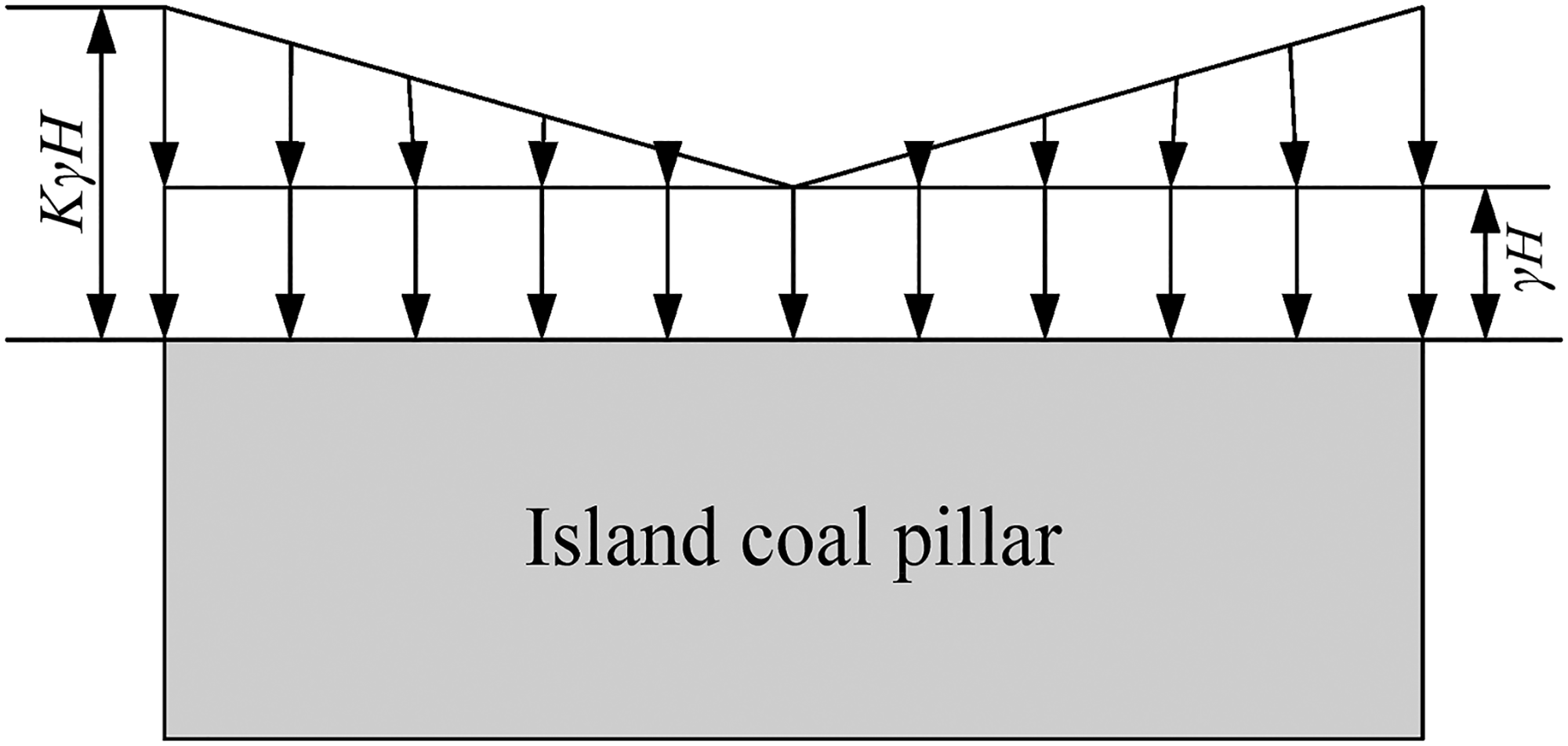
Simplified stress map of island coal pillar.
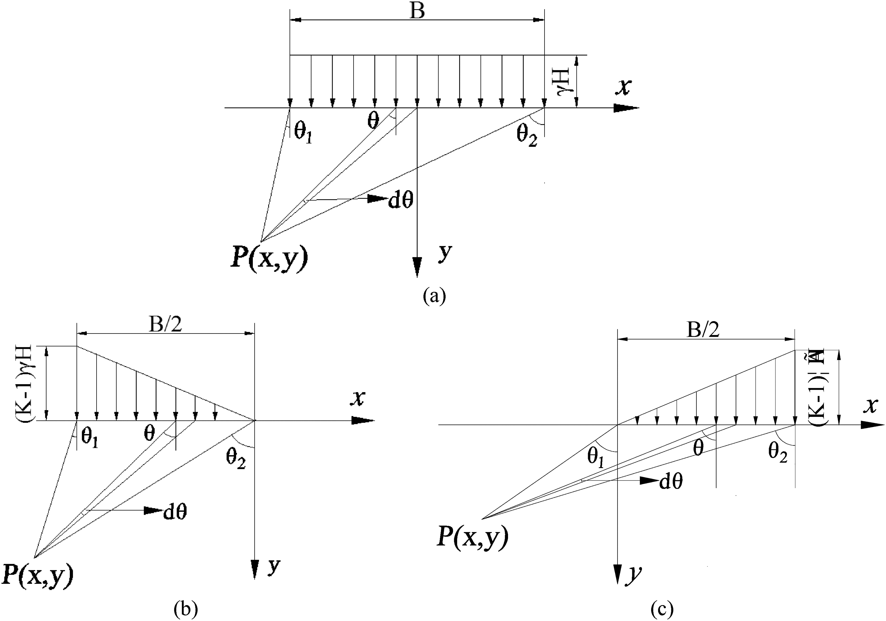
Stress calculating map of bottom slicing under island coal pillar: (a) rectangular stress; (b) triangular stress on the right; (c) triangular stress on the left.
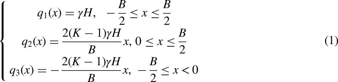
In the island coal pillar, assuming the coal pillar width is B; in-situ stress is
The stresses could be written as follows:
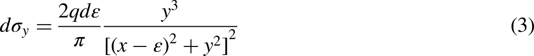
By simplifying coal and rock mass as elastic medium and using elastic mechanics theory (Wang et al., 2022b), under the action of concentrated stress, the vertical stress of a point in the plane could be expressed as follows:
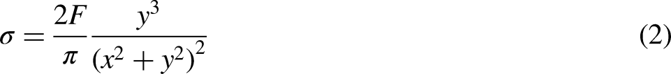
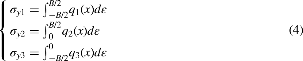
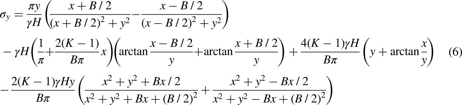
Taking differential element in coal pillar, the stress of point (x, y) could be expressed as follows:

Island coal pillar width B value
To obtain a stress distribution image of bottom slicing with contrasting coal pillar width, K value is assumed to be 3, and B value is assumed to be 80, 100, 120, 150 and 180 m, respectively (Figure 3). From Figure 3, except for the case of 80 m, the stress concentration factors of bottom slicing range between 0 and 2.5 with increasing B value. However, the width and depth of stress increased area (stress concentration factor more than 2) increases with increasing B value in bottom slicing. This indicates that a wide coal pillar could give the same stress increment but a larger stress-increased area than a narrow coal pillar. When the B value is set at 100, 120, 150 and 180 m, respectively, the width of stress increased area have increment of 19, 22, 26 and 32 m. Therefore, the increasing B value would increase rockburst risk, which indicates that entry in bottom slicing should avoid the stress increased area.
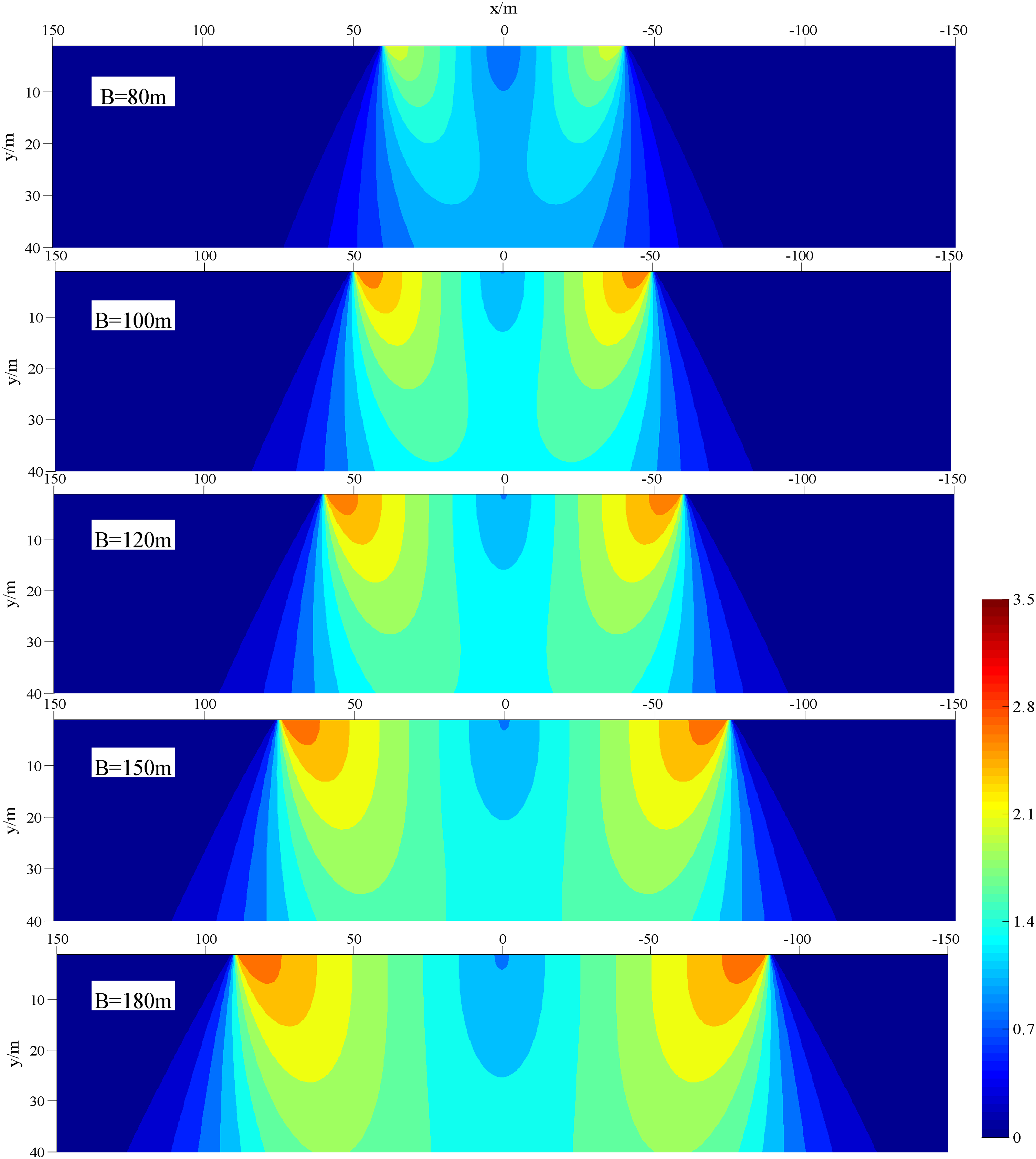
Stress distribution image of bottom slicing with contrasting B values.
Stress concentration factor K value
Figure 4 shows the stress distribution image of the bottom slicing with contrasting stress concentration factor K value, B value is assumed to be 120 m. According to Figure 4, K value has a significant effect on the stress distribution in bottom slicing seam. As the K value increases, the stress concentration factor in bottom slicing rapidly increases, particularly under the edge of coal pillar. This results in accelerated stress change and gradual increase in the stress concentration coefficient. Higher K value can easily induce shear failure of bottom slicing. Moreover, the width and depth of stress increased area expand with increasing K value. In addition, the stress extension angle also shows an increasing trend with increasing K value. Therefore, it can be concluded that K value has a higher degree of effect on stress distribution of bottom slicing compared to B value.

Stress distribution image of bottom slicing with contrasting stress concentration factor.
A method of AEE
The location of AEE
According to the stress distribution of bottom slicing, the increase in distance to coal wall gradually decreases the vertical stress of stress relaxed area. In order to effectively prevent rockburst, both static and dynamic stress should be reduced. Furthermore, it is important for the entry to be located in fully relaxed stress area. Research has shown that 10% of in-situ stress could be taken as a critical value, indicating that stress <10% has no effect on entry. Hence, focus should be placed on the contour line of 10% (Zhang et al., 2012). The included angle between the contour line (10%) and the vertical line is defined as stress relaxed angle
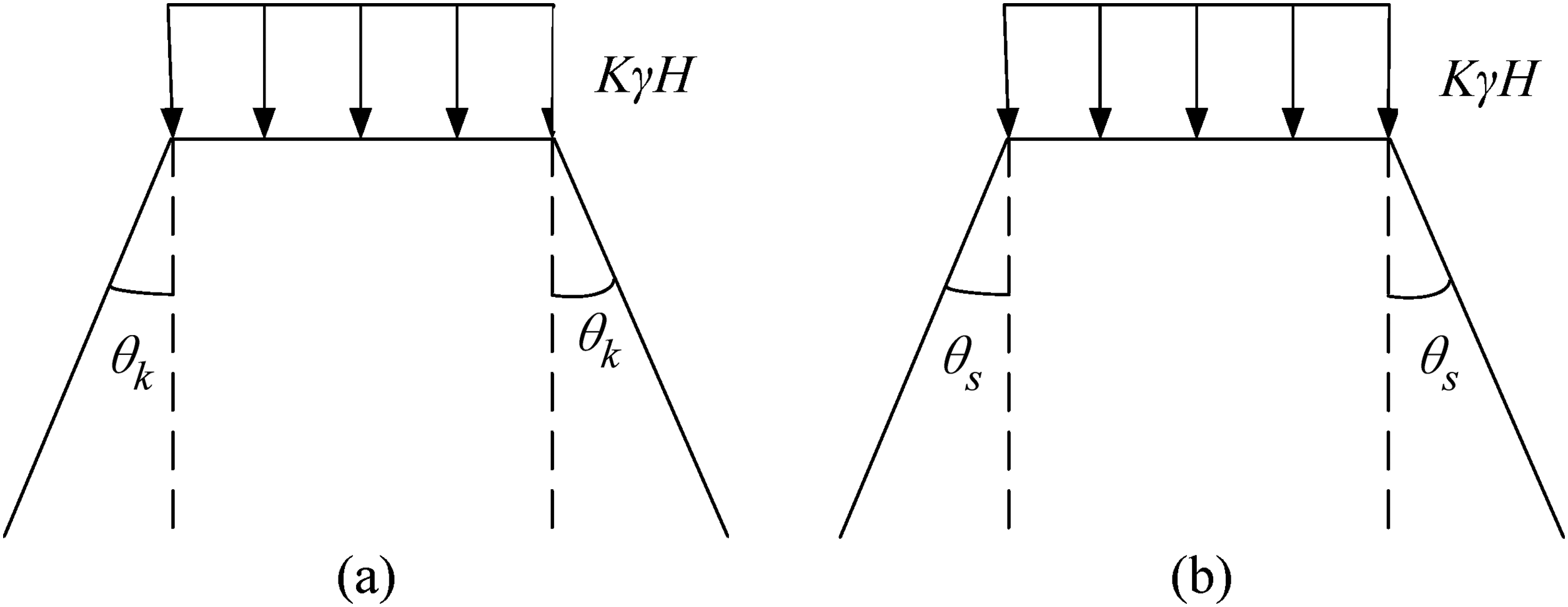
Stress map of bottom slicing under island coal pillar: (a) stress relaxed angle; (b) stress rate angle.
In a stress-relaxed area, the heterogeneous stress field could present a significant threat to entry protection. To avoid shear failure, the stress rate

In summary, the entry in bottom slicing should be positioned outside the stress concentration and shear stress areas. The stress extension angle


Sketch map of alternate exterior entry (AEE): (a) plan; (b) section.
According to equation (9), after determining the value of
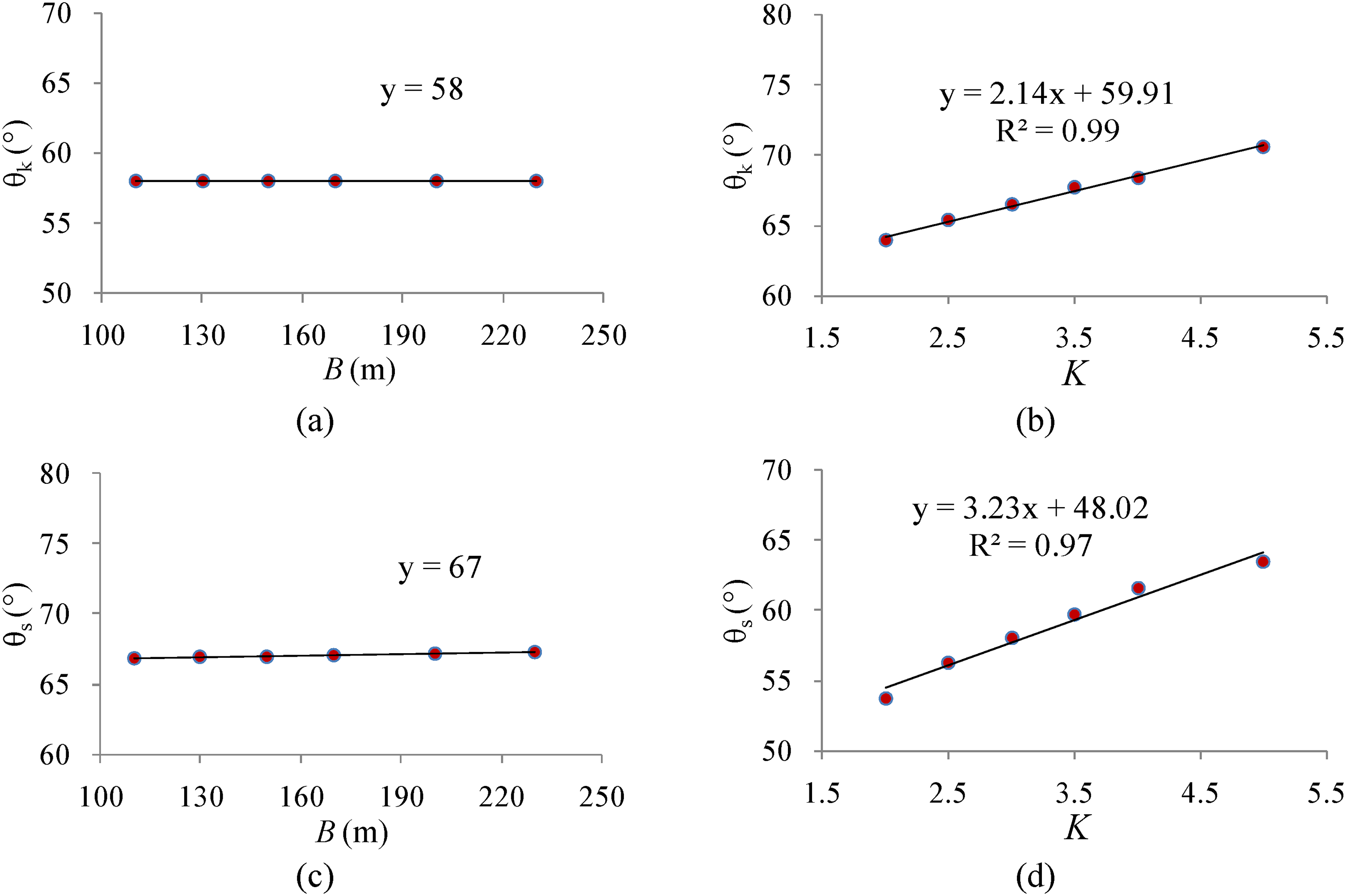
The determination of stress extension angle
Figure 7 shows the vibration rules of


The determination of stress extension angle in bottom slicing.
Therefore, the stress concentration factor should be mainly considered for AEE in bottom slicing although the width of the coal pillar is also an important factor. While
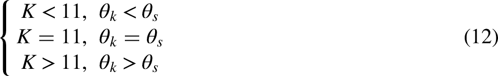
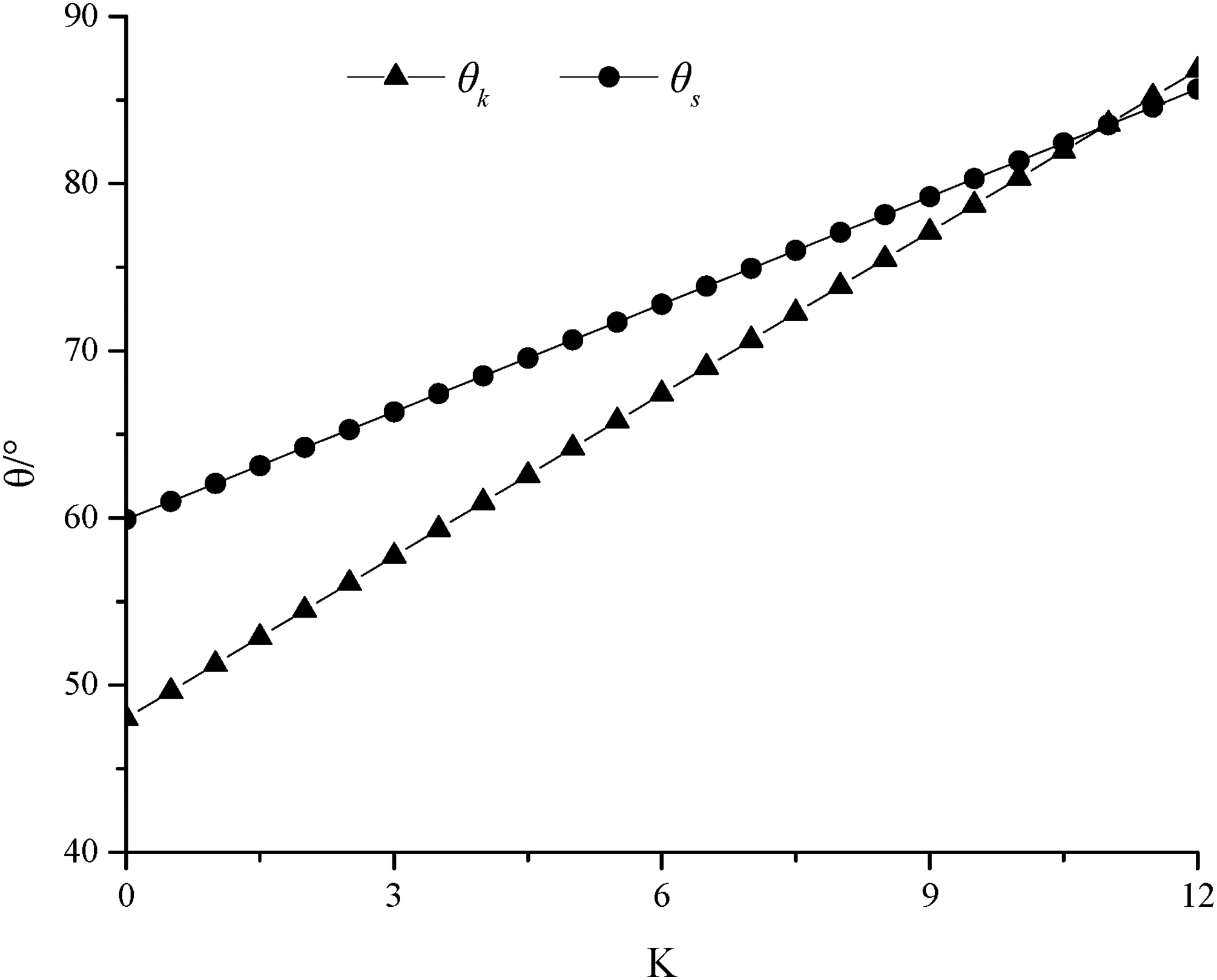
Contrast curves of
However, in the coal mine field, due to the physical and mechanical properties of coal and rock mass, the stress concentration factor acts as
Field verification of AEE
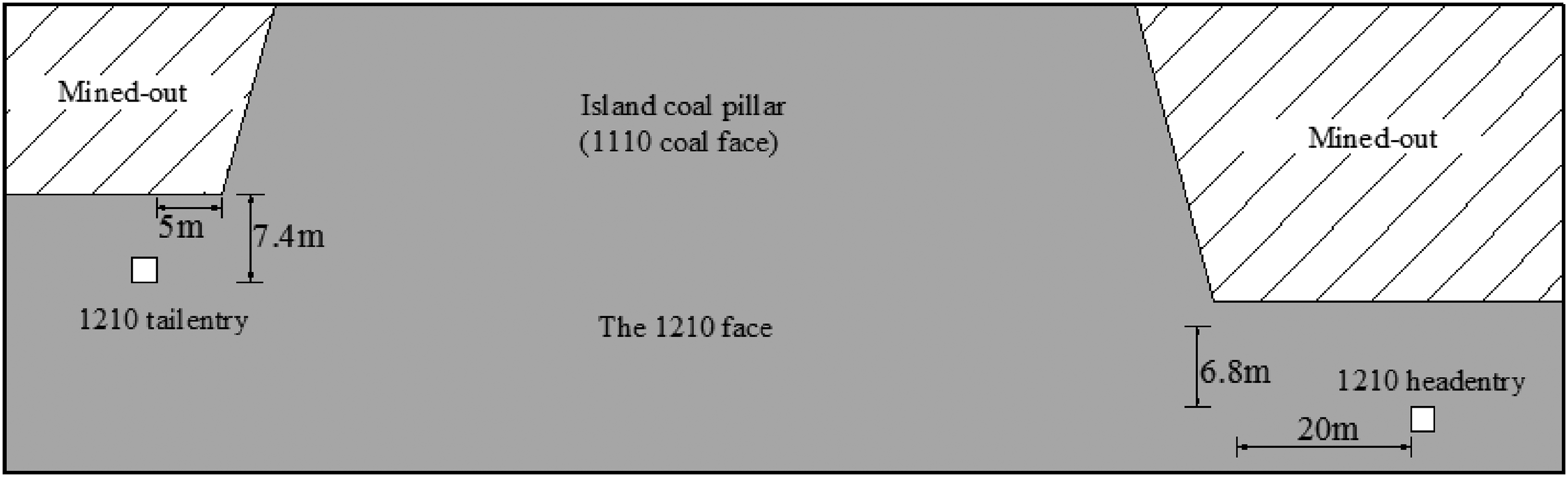
The verification of AEE is according to the 1210 coal face, which is situated in the southern district of −430 m horizontal level in Barapukuria Coal Mine. The thickness of the coal seam is 40 m. The top layering with a thickness of 15.7 m has been mined out except for the 1110 coal face, which is the island coal pillar. The 1210 coal face is the first coal face of the second layering the thickness 24.3 m. The coal face's effective strike is 342 m, the sloping length is 154 m, and the average dip angle is 7.6° (Figure 9). Therefore, the method of AEE has been carried out. The distances between tailentry and coal pillar are horizontal (5 m) and vertical (7.4 m); the distances for headentry are horizontal (20 m) and vertical (6.8 m).
The alternate exterior entry (AEE) parameters for entries in the 1210 coal face.
According to field measurement results,
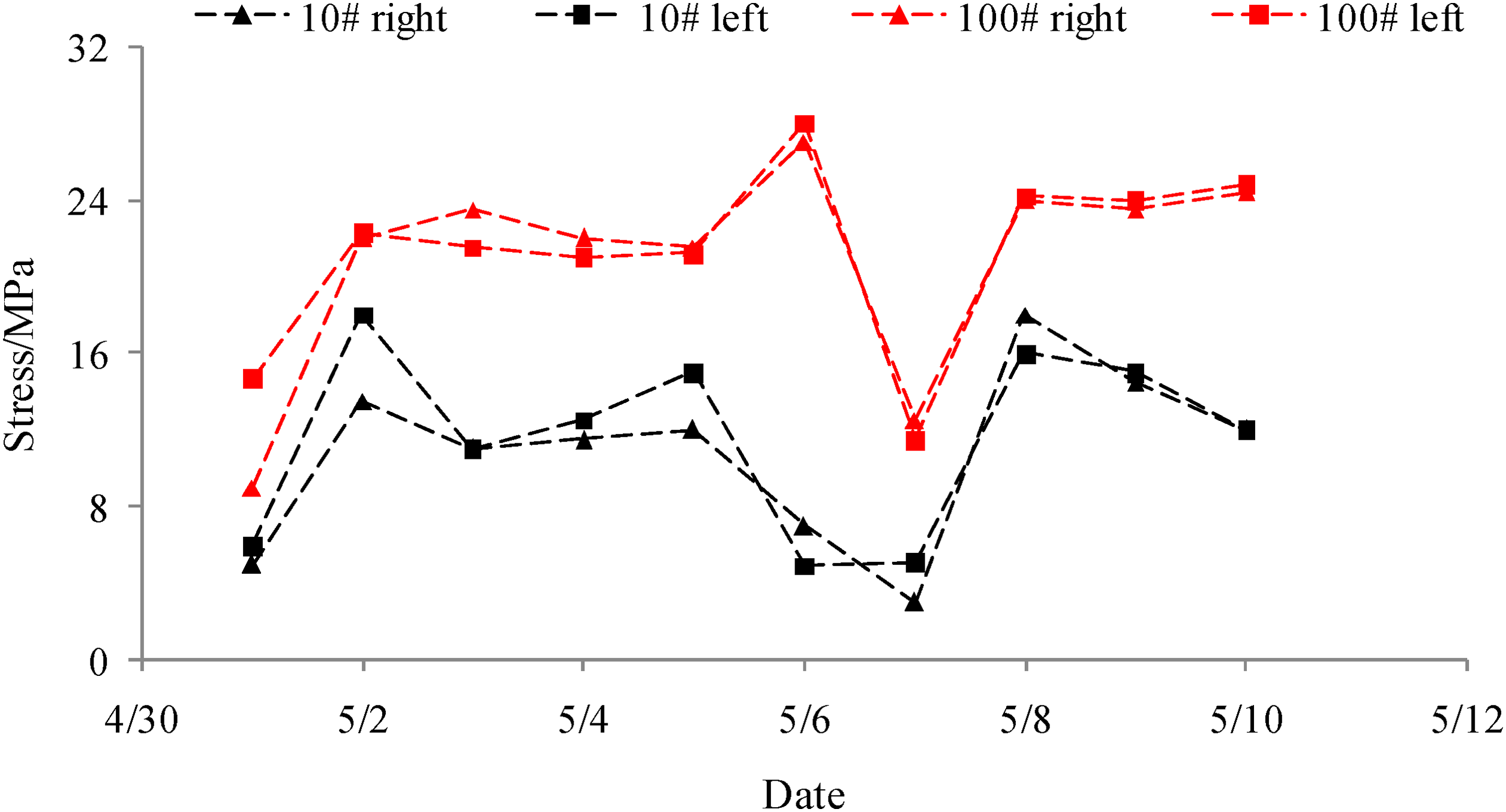
The stress curves of 10# and 100# support the 1210 coal face.
Numerical simulation on the AEE method
In the Barapukuria Coal Mine, the mining-out of the top layer of the coal seam enabled the island coal pillar to protect the down entry. For a long time, the deformation of entry under the island coal pillar was vast and significant due to high-stress levels and had induced a number of rockbursts. However, to meet the ventilation requirements of successive coal face operations, a special tailentry had to be arranged under the island coal pillar. This study utilizes numerical simulation to explore the optimized location of the tailentry in order to prevent rockburst.
The pre-set plans of tailentry
In the Barapukuria Coal Mine, the coal seam is 39 m thick and the roof (sandstone) is 120 m thick in the south mining area. The mined-out areas are 12 coal faces of 1104, 1106, 1108, 1110, 1112, 1114, 1116, 1101, 1103, 1105, 1109 and 1111 (Figure 11). The island coal pillar is located in a high-stress area.
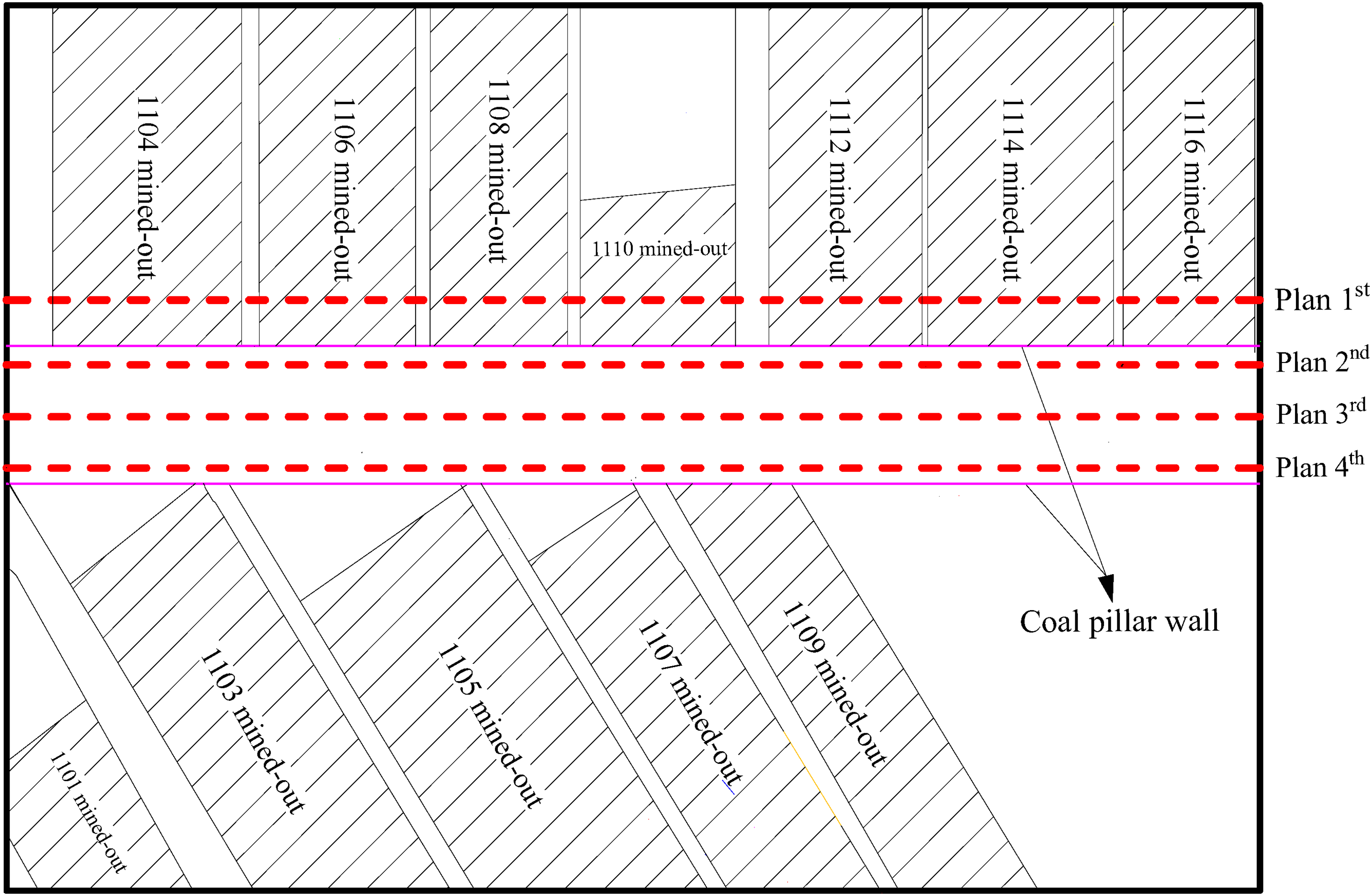
Four plans of alternate exterior entry (AEE) of in Barapukuria coal mine.
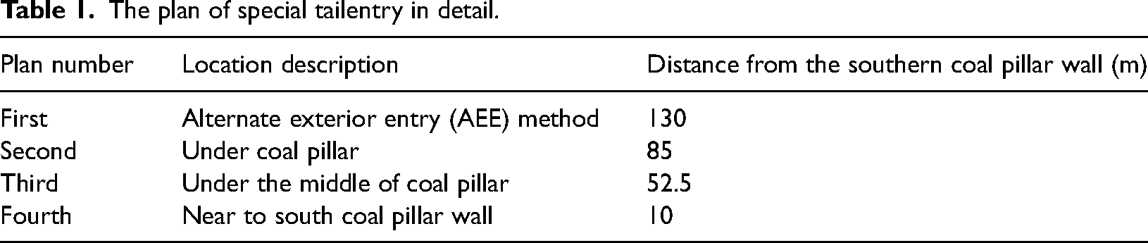
To explore the process of mechanical changes in tailentry surroundings, geological data of the south mining area in Barapukuria Coal Mine was taken for background study. Four plans of tailentry were arranged as shown in Table 1. The section of the tailentry is a rectangle with 5 m × 3 m in width and height all arranged 10 m above the floor. The original point is located on the southern coal pillar wall.
The plan of special tailentry in detail.
Numerical model by Flac3D
Model size
A 3D numerical model where the size is 950 m (length) × 670 m (length) × 240 m (height) was constructed by Flac3D, which included 446,975 elements and 487,450 nodes. During the static equilibrium stage, considering the simulated vertical depth (273 m) of the model, vertical stress (6.825 MPa) and horizontal stress (8.19 MPa) were applied to account for overburden. The horizontal displacements of the front, back, left, and right boundaries, as well as the vertical displacement of the bottom boundary in the entire model, are all fixed.
Model parameters
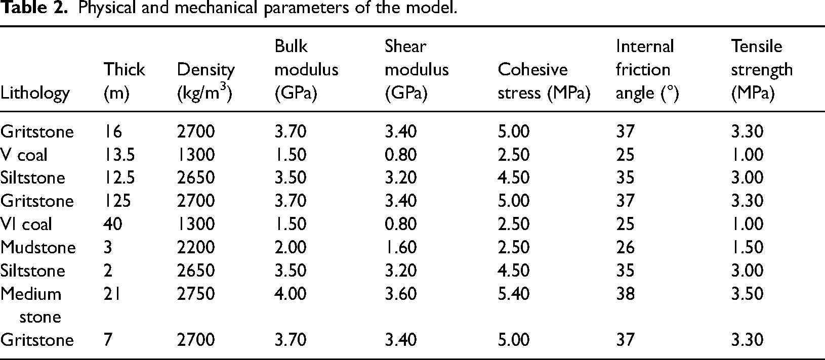
The Mohr-Coulomb failure criterion was adopted to represent the plastic behaviour of coal and rock mass (Itasca Consulting Group, Inc, 2017). Based on geological investigations and mechanical tests, the physical and mechanical parameters of each sub-layer of the model are given in Table 2.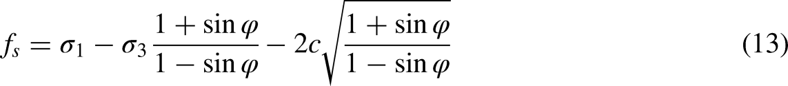
Physical and mechanical parameters of the model.
Numerical simulation process
To explore the effect of AEE on rockburst prevention, the stress and deformation of the specialized tailentry are recorded during the numerical simulation process, which is shown in Figure 12 in detail.
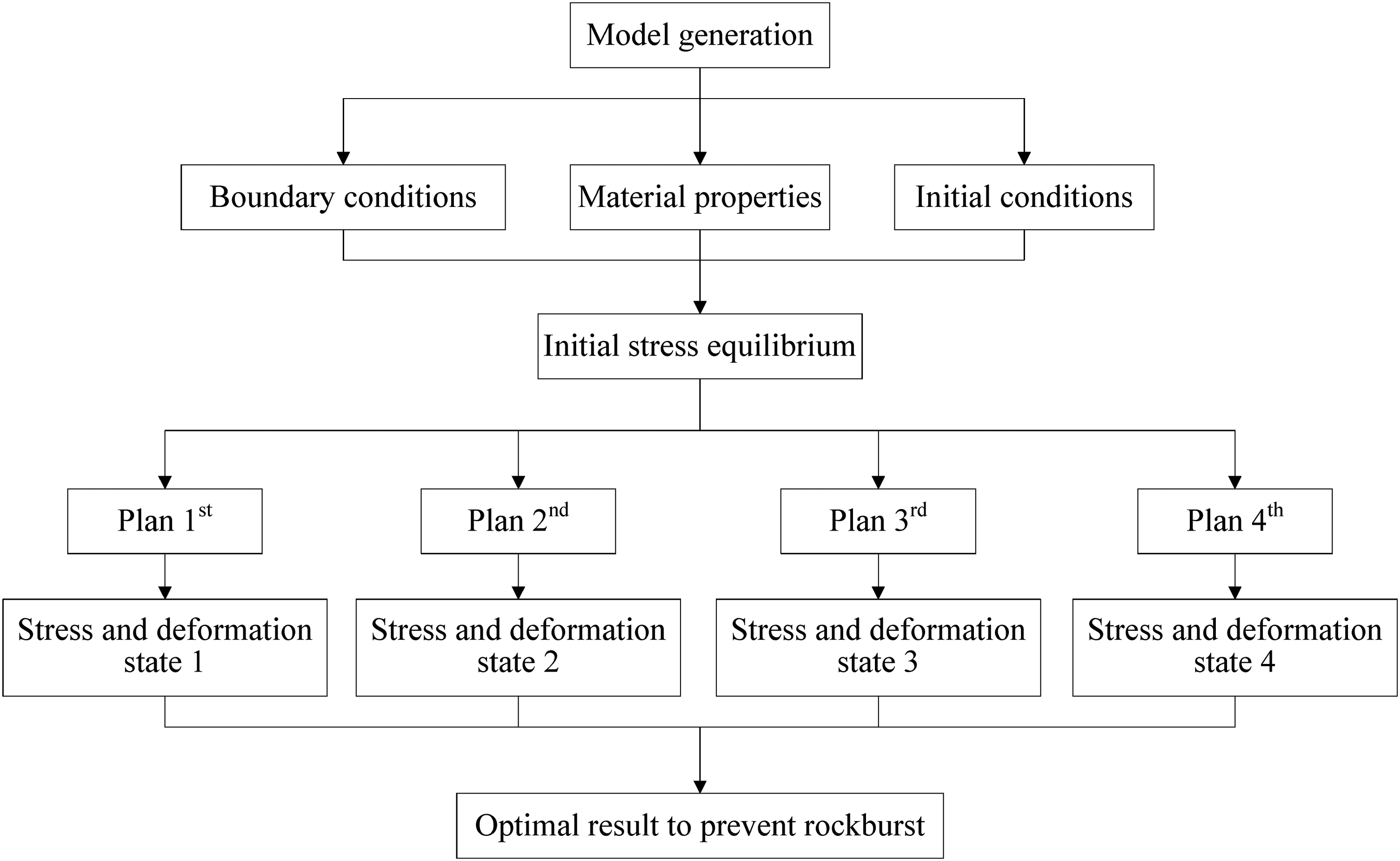
The numerical simulation process of alternate exterior entry (AEE) method by FLAC3D.
The analysis of results
The high-stress concentration of coal pillar
Located at a depth of 380 m, the top layering has an in-situ stress of 9.5 MPa. After the coal faces were mined-out and the model reached stress equilibrium, the image of the stress at the top layering coal was obtained, as shown in Figure 13.
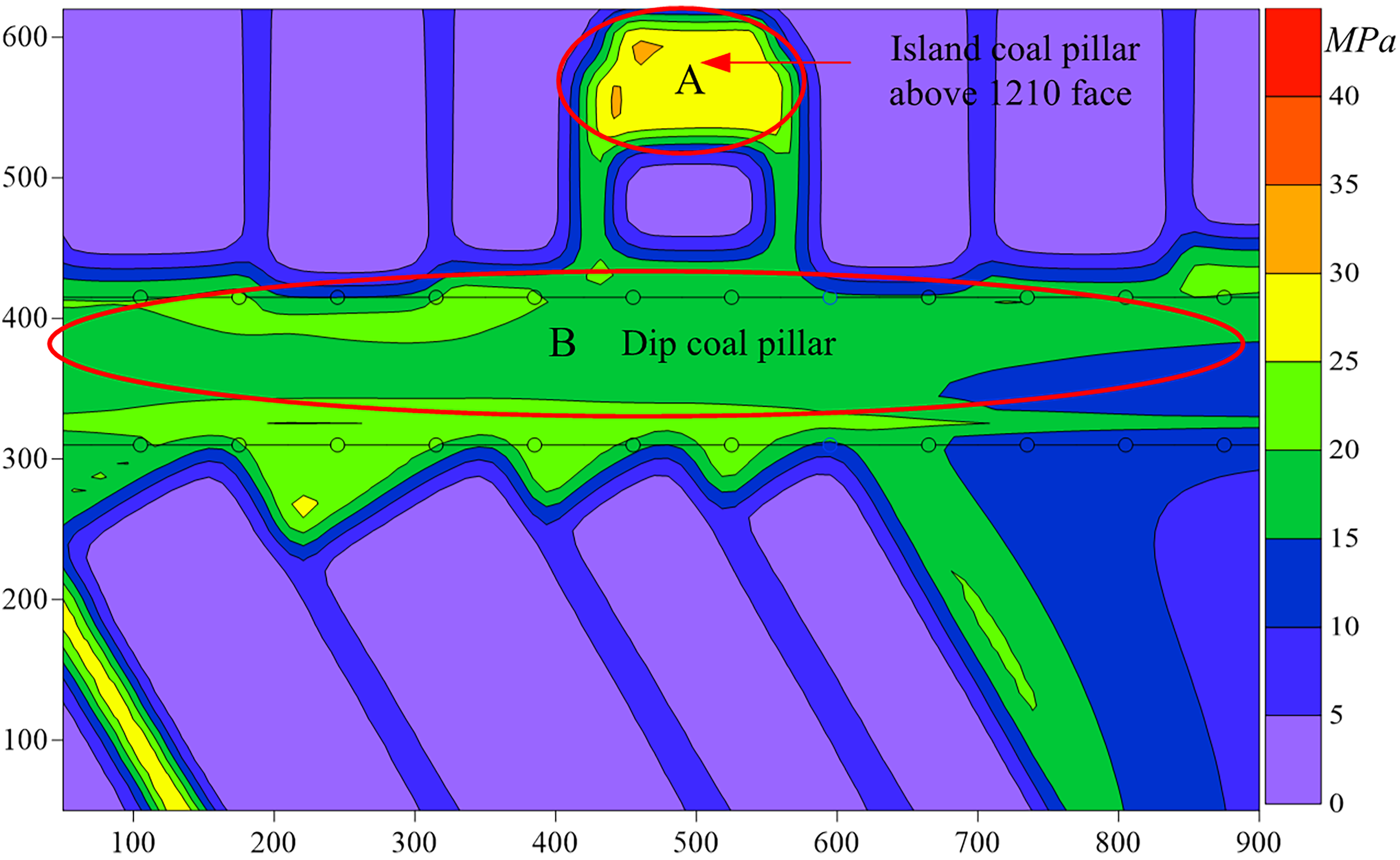
Image of the stress at top layering coal by numerical simulation.
From Figure 13, region A is the island coal pillar above the 1210 coal face, and region B is the dip coal pillar. The peak values of stress in region A is 36 MPa and region B is 25 MPa. Based on in-situ stress of 9.5 Mpa, this indicates that there are stress concentration factors of 3.8 for region A and 2.8 for region B. The stress redistribution induced the high-stress concentration. However, it is noted that the edge of the coal pillar is stress-relaxed area where special tailentry was arranged to prevent rockburst.
Compared and analyzed on special tailentry (four plans) by stress and deformation
Based on the monitoring mechanism of rockburst and early warning by stress and deformation (Lu et al., 2015; Zhu et al., 2016), and using software to process the data in the model, the vertical stress and deformation of the special tailentry were obtained (Figure 14).
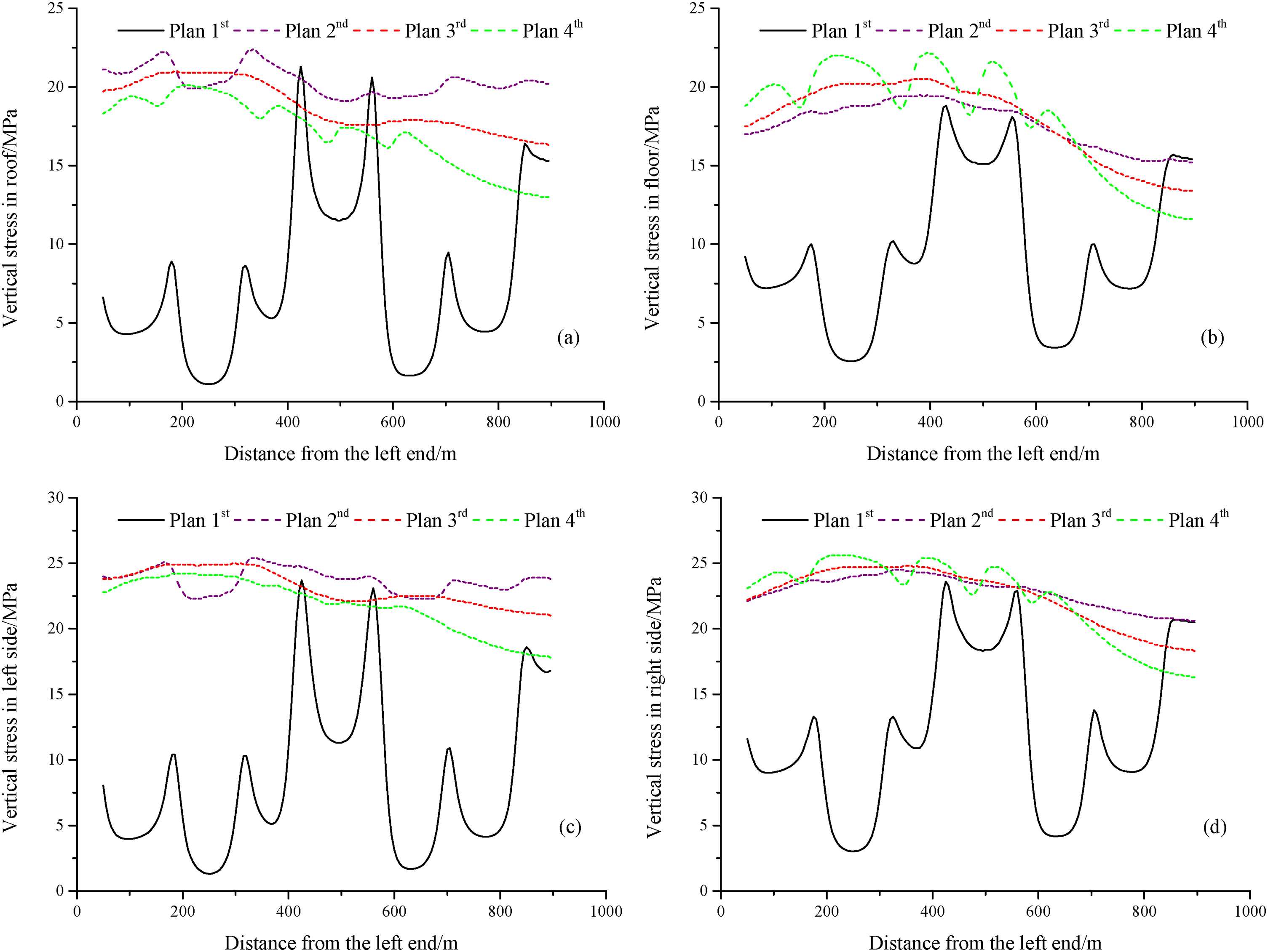
The vertical stress and deformation of the special tailentry (four plans).
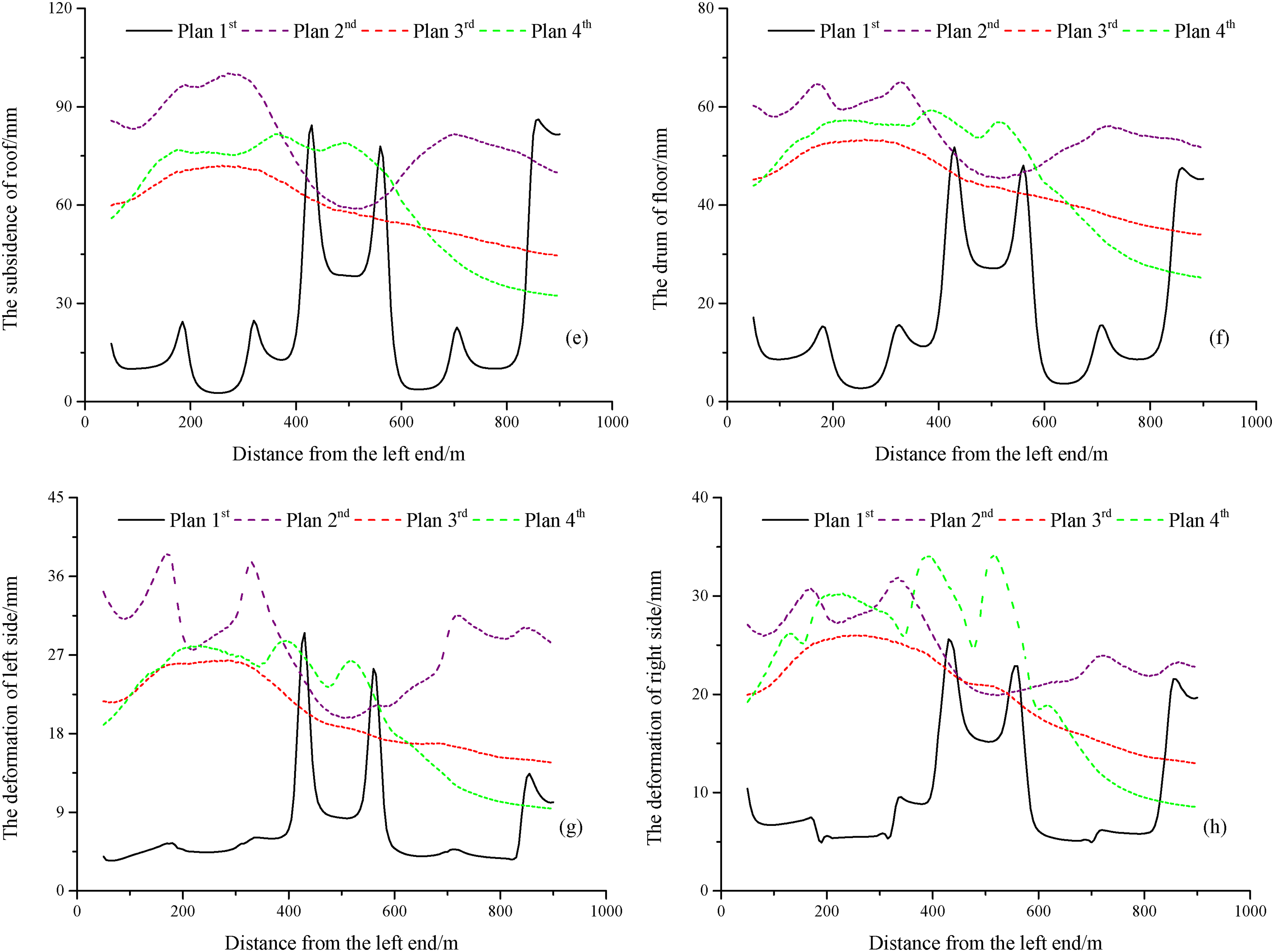
According to Figure 14, through comparative analysis of vertical stress and deformation of plans first, second, third and fourth, four key points could be proposed: (1) the vertical stress and deformation of plan first is significantly lower than that of plans second, third and fourth. This indicates that plan first is in stress-relaxed area and is the most effective way to prevent rockburst. However, at the corner of the 1110 and 1114 coal faces, there are abnormally high levels of vertical stress and deformation which may be caused by an unreasonable stopping line. (2) In plans second, third and fourth, the vertical stress and deformation of plan third are stable, while those of plans second and fourth have violent fluctuations, possibly induced by the serrated stopping line. (3) The deformations of tailentry sides are much lower than those of roof and floor tailentry. This indicates that high vertical stress and low horizontal stress in the island coal pillar. Therefore, the focus should be on vertical stress to prevent rockburst. (4) The deformation of plan third is smaller than those of plans second and fourth in roof and floor, while their stresses are high. This indicates that the elastic state in the middle area of the coal pillar thus contains a large amount of elastic energy, while the edge areas of the coal pillar are in a plastic state, and its elastic energy has been released.
In summary, in island coal pillar, the vertical stress is the main factor in inducing rockburst. Plan third contains a large amount of elastic energy and has the highest risk of rockburst, while plan first is in a stress-relaxed area. Therefore, plan first is the most effective way to prevent rockburst.
Conclusions
For the mining of extremely thick coal seam, slicing mining is usually adopted to raise the recovery ratio, avoid spontaneous combustion and prevent gas accumulation. However, due to limitations in geological conditions, technology and mining layout, several island coal pillars have to be left behind, which easily induces rockburst in the mining of bottom slicing. To solve this problem, this paper proposed an AEE method to prevent rockburst.
Using two-dimensional (x and y) stress image, the effects of B and K values on the stress distribution were explored. It was found that k value has a higher degree of effect on stress distribution of bottom slicing compared to B value. As B value increases, both the stress relaxed angle and stress rate relaxed angle remain constant, and the value is 58° and 67°, respectively, but with increasing k value, the angles both increase linearly as suggested by trend lines of
Finally, using numerical simulation, the optimized location of the special tailentry under the dip island coal pillar was explored to prevent rockburst. Plan third contained a large amount of elastic energy and had the highest risk of rockburst, while plan first was the most effective approach to prevent rockburst, as it was in stress relaxed area, which also verified the AEE method.
Footnotes
Data availability
The datasets used and analysed during the current study are available from the corresponding author on reasonable request.
Declaration of conflicting interests
The author(s) declared no potential conflicts of interest with respect to the research, authorship, and/or publication of this article.
Funding
The author(s) disclosed receipt of the following financial support for the research, authorship, and/or publication of this article: This work was supported by Key Research and Development Project of Henan Province in China, Fundamental Research Program of Shanxi Province, Doctoral Research Start-up Fund Project, Nanyang Institute of Technology, Collaborative Innovation Center for Prevention and Control of Mountain Geological Hazards of Zhejiang Province, Interdisciplinary Sciences Project, Nanyang Institute of Technology, Sponsors of the Natural Science Foundation of Henan, Basic and Frontier Technology Research Project of Nanyang City, Key Scientific Research Projects for Higher Education of Henan Province, National Natural Science Foundation of China (grant numbers 242102320216, 232102320182,20210302124633, NGBJ-2022-17, PCMGH-2022-05, NGJC-2022-02, 242300420353, 23JCQY2014, 23A440012, 23A560017,24A440011, 52104127, U21A20108, U22A20620 and 52174108).