
Abstract
The preload of ball screws is generally used to confirm the ball screws with a high axial contact stiffness and a high positioning accuracy. Aiming at the preload degradation due to wear on the raceway of double-nut ball screws, a wear distribution model was proposed by calculating the contact stress distribution and the inhomogeneous relative sliding velocity distribution on the contact region to determine the wear profile of the raceway. Firstly, the contact stress distribution and the relative sliding velocity distribution on the contact surface were determined using the kinematics analysis and the force balance analysis. Subsequently, a wear distribution model was established to determine the wear depth distribution of the contact surface based on elastic-plastic contact mechanics of asperity with consideration of the microscopic characteristics of the raceway. Finally, the three-level step-stress accelerated degradation test based on the simulated model was designed and implemented on a self-designed bench to validate the proposed model. Experimentally measured friction torques of the ball screws were used to reflect the preload degradation, and they were compared with the results of the simulated model. The results showed that the degradation curves of the experimental friction torques and the wear profiles of screw raceways were in good agreement with the numerical results, confirming the correctness and effectiveness of the proposed model. The results indicated that the wear profile of the raceway could be accurately calculated based on the proposed model, clearly describing the wear process of the raceway surface and providing a more precise approach to predict preload degradation for ball screws.
Keywords
Introduction
Due to its advantage of high-speed, high-precision, and high-transmission efficiency, a ball screw is the major precision transmission component of modern machine tools. However, the increased probability of preload degradation owing to the long-term operation affects the positioning accuracy of ball screws.1,2 The preload degradation of ball screws is mainly affected by the raceway wear. It is therefore highly essential to study raceway wear since the raceway wear is a complex process using kinematics, force balance, and contact mechanics.3–5
In terms of the kinematics and force balance analyses of ball screws, balls can generate inertial force regardless of whether the screw rotates at a constant or accelerated speed. To reduce the difficulty of mechanical analysis, a number of scholars neglected the effects of inertial force in a low-speed ball screw.6–8 As a ball screw develops toward high-speed, the inertial force increases significantly. Thus, these theoretical models seem to be complicated to satisfy the high-speed operational conditions. Zhou et al. 9 proposed a modified load distribution model considering the deformations of the screw and nut, which can obtain the critical axial loads of double-nut ball screws. Brecher et al. 10 proposed a new method to determine the force distribution of each operating ball for ball screws, and this method was used to analyze the influences of the elastic deformation of the nut and screw on each ball contact, concerning normal force, and contact angle. Li et al. 11 studied the force balance of the ball screws considering the thermal elongation, and an adaptive on-line compensation method was proposed to reduce the positioning error. Bertolino et al. 12 analyzed the relationship between the no-load friction torque and the preload of the double-nut ball screws, considering the screw speed and geometry. The above-mentioned studies investigated the contact characteristics of ball screws from a macroscopic perspective, which did not accurately calculate the relative sliding velocity distribution on the meshed contact regions.
In case of the raceway wear and preload degradation of ball screws, the relative slip motion 13 between the ball and raceway may generate the wear removal of materials on the contact surfaces, which is the major factor of variation of positioning accuracy and other performance indicators for ball screws. In terms of the study of wear prediction of ball screws, the traditional Archard adhesive wear model has been extensively used,14–16 whereas it is highly appropriate for the sliding wear, without consideration of the rolling-sliding mixed motion at the contact surfaces. Lin et al. 17 established a low order static load distribution model of the ball screws that incorporates lateral deformation and geometric error effects. Zhou et al. 18 proposed a new correlation between preload and no-load friction torque, and the preload degradation can be derived by the real-time measured no-load friction load. Han et al. 19 analyzed the vibration signal of ball screws using fractal theory and taken the fractal parameter G as an effective parameter into account for evaluating the lubrication degradation. Nguyen et al. 20 presented a method to monitor the preload of the ball screws by evaluating the natural frequency of the screw nut in the axial direction and the corresponding working table displacement. Zhou et al. 21 proposed a preload degradation model of linear rolling guide considering both the micro-contact behavior and the intermittent wear behavior between the rolling element and raceway, and which was verified by the experiment. It is noteworthy that the inhomogeneous distribution of the wear depth could be accurately calculated to predict the preload degradation of ball screws. Huang et al. 22 used the vector machine to diagnose the preload degradation of ball screws in the absence of prominent characteristic features in data. However, only the maximum wear depth in the raceway contact region was calculated in the above-mentioned studies, which cannot describe the wear profile and the wear process of the raceway accurately. Then the prediction of the preload degradation of ball screws was more accurate using the wear depth distribution than the maximum wear depth.
To reveal the accurate wear profile of the raceway and the preload degradation mechanism of ball screws, a wear distribution model is proposed by calculating the contact stress distribution and relative sliding velocity distribution on the contact region in this paper. According to the modification of preload with the increase of the raceway wear depth continuously, the raceway wear distribution curve and the preload degradation curve are determined by the proposed model. Additionally, the three-level step-stress accelerated degradation test is designed and implemented based on the simulated model using friction torque acquired from real-time testing data to verify the numerical model. The theoretical schematic diagram of the wear distribution model in this research is shown in Figure 1.
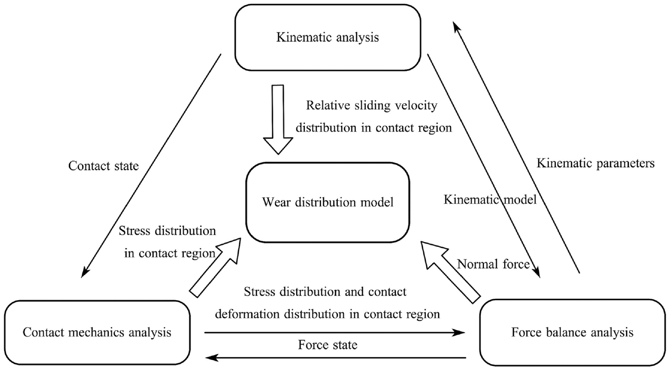
Theoretical schematic diagram of the wear distribution model.
Modeling of the raceway wear distribution
The wear distribution model of ball screws consists of three parts: distribution of contact stress and relative sliding velocity, fractal adhesive wear model, and wear distribution model.
Relationship of the raceway normal contact deformation with the preload degradation
As shown in Figure 2(b), the axial gap between the nuts varies by a preloaded washer, leading to elastic deformation of the ball with the screw raceway and the nut raceway. The preloaded deformation
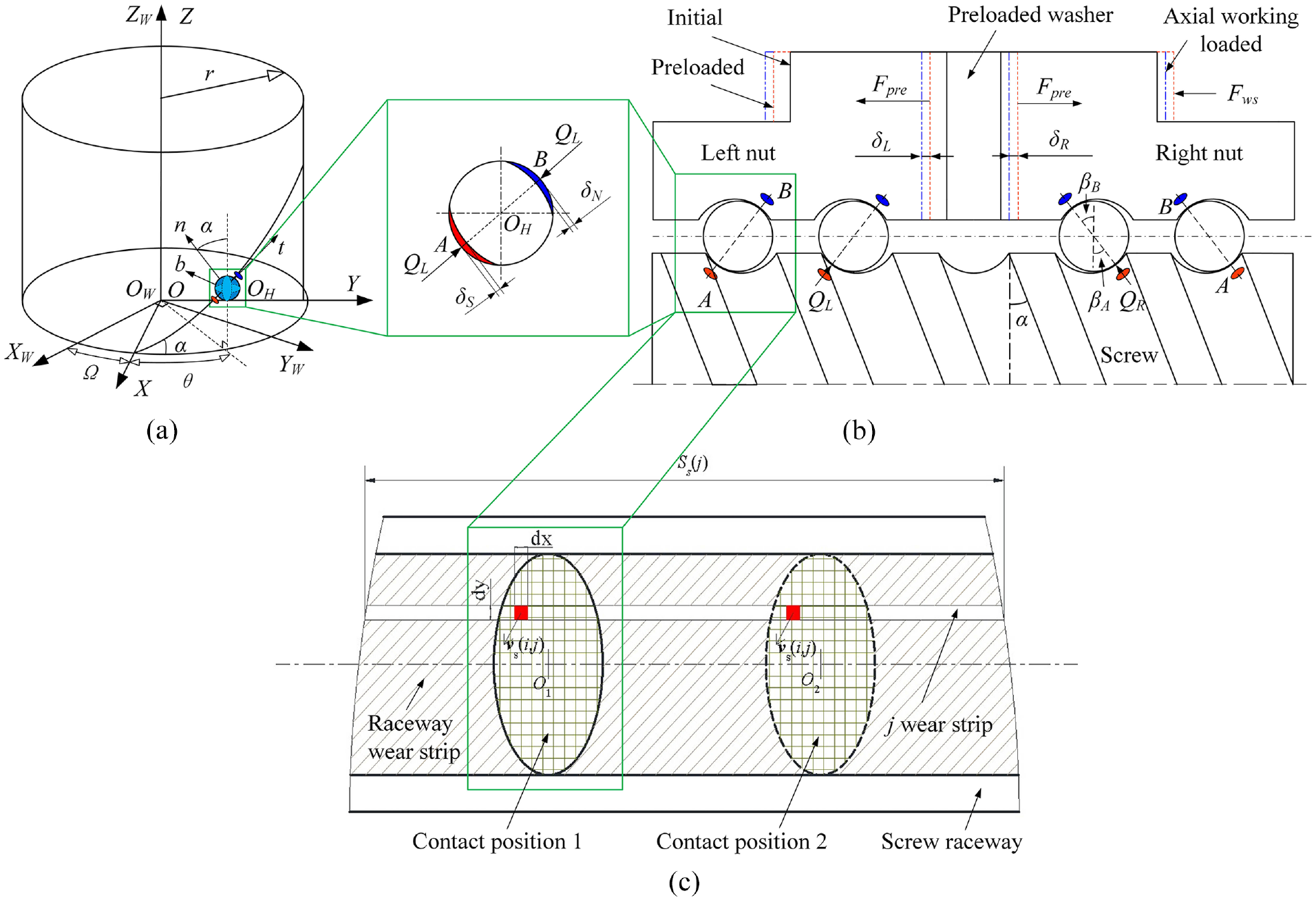
Force analysis of double-nut ball screws (a) Coordinate systems. (b) Force analysis. (c) Wear distribution of raceway.
When the preload
The relationship between the axial preloaded deformation of the left nut and normal contact deformations at the contact point A and at the contact point B is given by
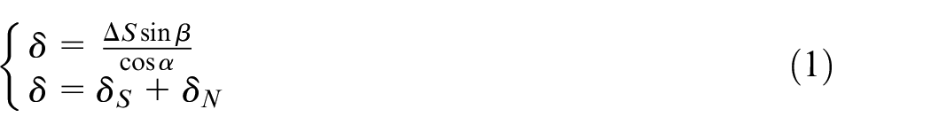
The previously reported relationship 23 between the nut axial preloaded deformation and the preload is expressed as
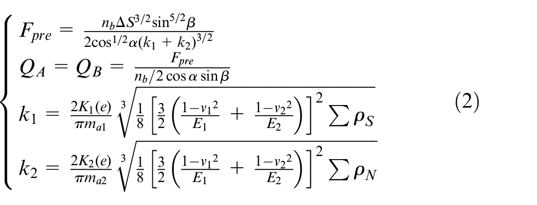
where
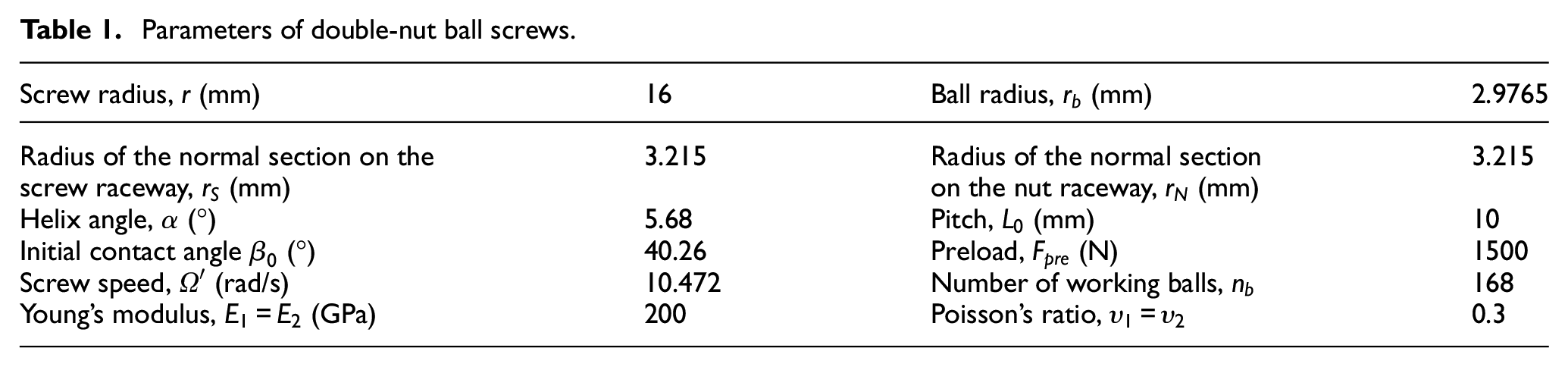
Parameters of double-nut ball screws.
Distribution of the normal contact stress and relative sliding velocity on the contact region
Aiming at the kinematics analysis of ball screws, the coordinate systems of ball screws
24
should be set as shown in Figure 2(a). The coordinate system OWXWYWZW is established in space, and its ZW-axis is coincident with the axial direction of screw. The coordinate system OXYZ rotates with the angle
As shown in Figure 3, the Cartesian coordinate systems of AXAYA and BXBYB are established at the contact point A and the contact point B, respectively. The origins of both coordinate systems are located at the contact point A and the contact point B.
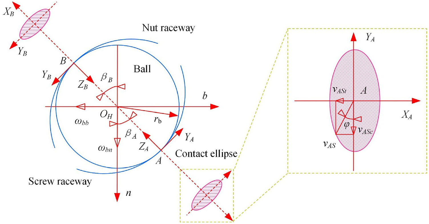
Distribution of the relative sliding velocity at the point A.
Considering the asymmetry of the contact area of the helical raceway of the ball screws, the normal contact stress is solved by the minimum excess principle.25–27 The distribution of contact deformation on the screw contact region is formulated as
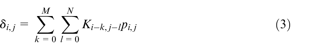
where,
The motions between the ball/screw-raceway and the ball/nut-raceway are not pure rolling simultaneously.
24
Besides,
where
Meanwhile, the spin velocity at the contact point B is equal to zero.

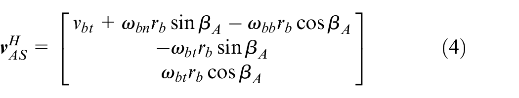
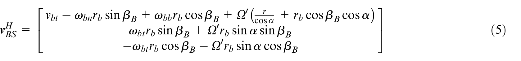
At the point A, the relative velocity of the ball with respect to the tangential direction of the helix track of the screw raceway is
Assume that
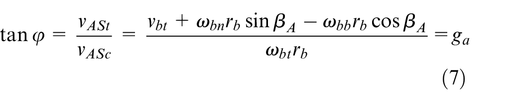
According to equations (4–7), equation (8) is written as,
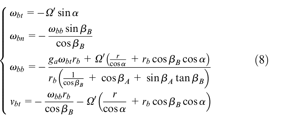
The relative sliding velocity between the ball and screw raceway is comprised of two relative linear velocity components (

Solution of the contact stress distribution and relative sliding velocity distribution on the contact region based on the equation of ball force balance
When the ball screw rotates at a constant speed, the working balls are in the quasi-static state and affected by force characteristics, such as normal force, friction, inertia force, lubricant film resistance, friction torque, inertia torque, and gyroscopic torque. The force balance equation and torque balance equation of the working ball are written as,
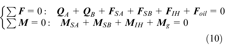
where,
The force balance equation and the torque balance equation are expanded in three coordinate directions of the OHtnb coordinate system, as shown in equation (11).

The initial value
The force and deformation balance equations can be expressed as,
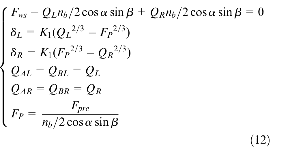
where,
The inputs of equation (11) are the screw speed
The contact stress distribution and relative sliding velocity distribution on the screw raceway contact region are displayed in Figure 4. The normal contact force at the point A decreases as the screw speed increases. The magnitude and direction of the relative sliding velocity are denoted by the size of arrow line and the direction of arrow. The relative sliding velocity is along the −YA direction in a low-speed operational status, while the relative sliding velocity in the −XA direction increases along with the elevation of the screw speed.
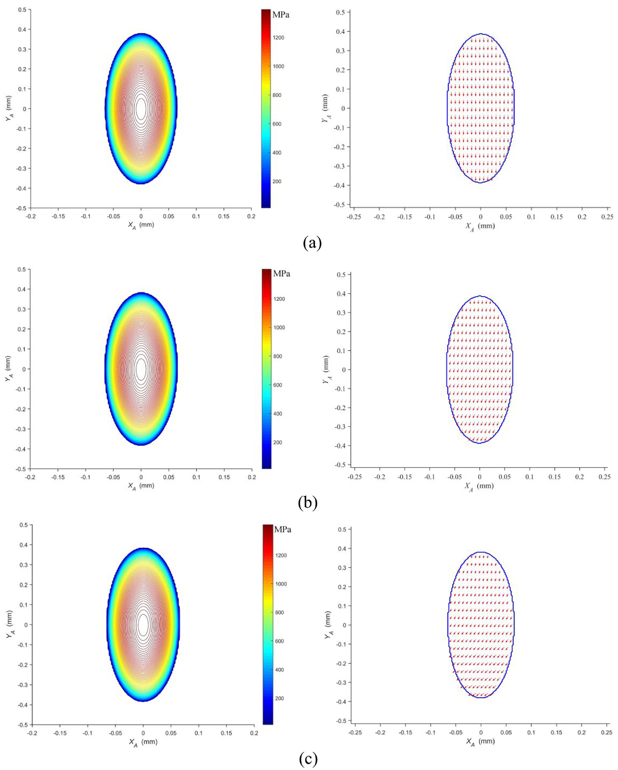
Distribution of the contact stress and the relative sliding velocity: (a)
Modeling of average contact pressure on themicro-contact region
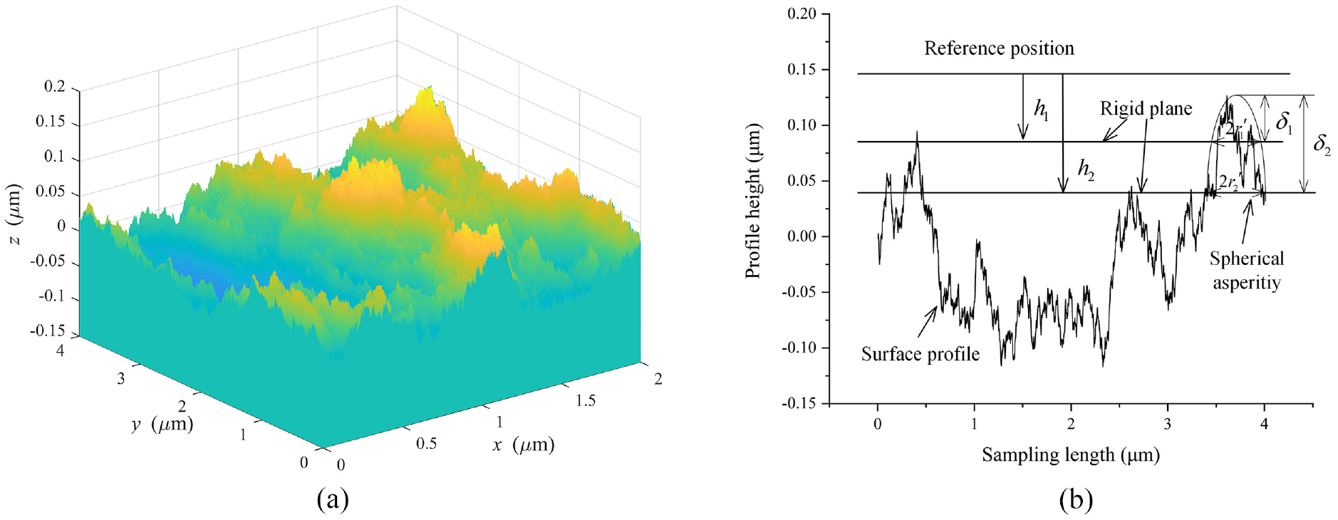
The topographic characteristics of the fractal micro-contact surface in all directions can be described by fractal surface, 29 and the influential factors include fractal dimension D and scale parameter G.
The three-dimensional (3D) topography and two-dimensional (2D) profile of the rough fractal surface
30
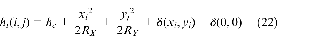
are shown in Figure 5(a). Due to the hardness of the working ball being higher than that of the screw raceway and the processing technology of the working ball being mature, the micro-contact area of the working ball is regarded as the rigid plane. As shown in Figure 5(b), the formation of truncated sections is caused by the increase of stepped indentation depth (


(a) Fractal surface topography and (b) surface profile truncated by the rigid plane.
The equivalent elastic modulus and the equivalent hardness are used in the contact system, which is comprised of the rigid smooth plane and the rough fractal surface.
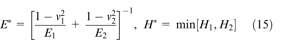
where,
The geometric relationship
where,
If
where,
The size distribution function 30 of micro-contact in the micro-contact region is formulated as,
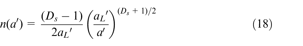
where,
The total truncated area of the micro-contact region is expressed as,
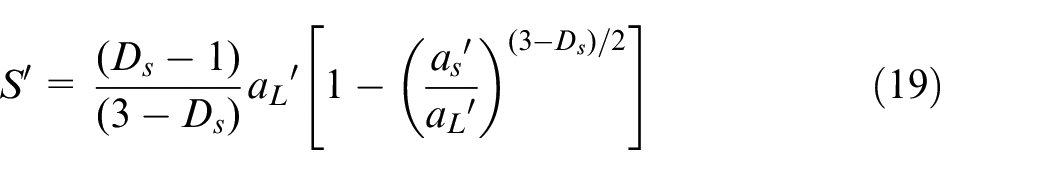
where,
The total truncated area of the micro-contact region is determined as,
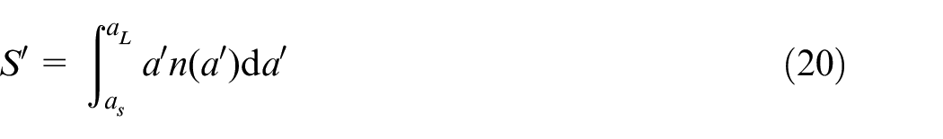
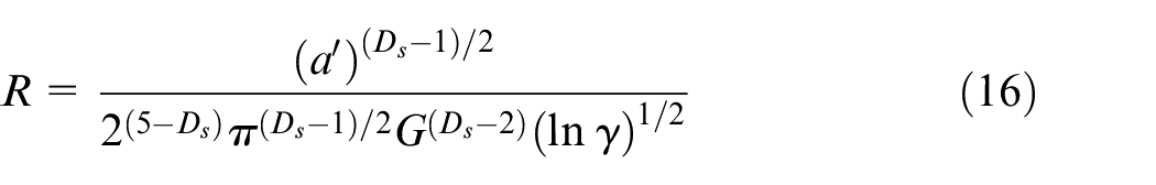
With substituting equation (19) into equation (20), the largest truncated area
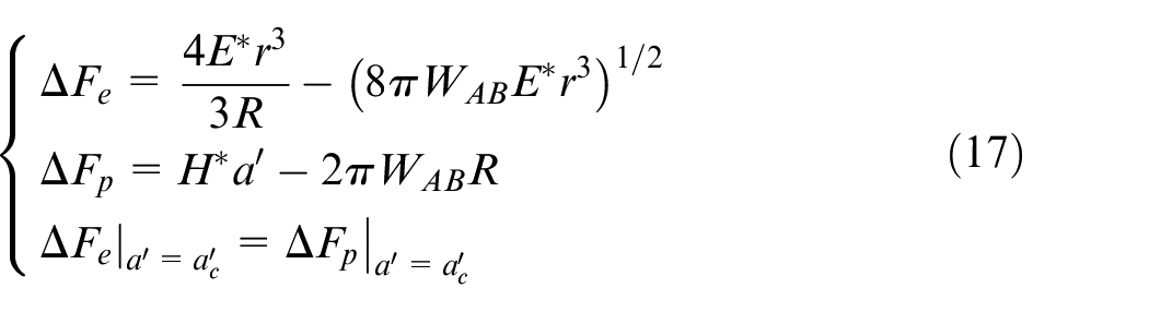
The total normal force
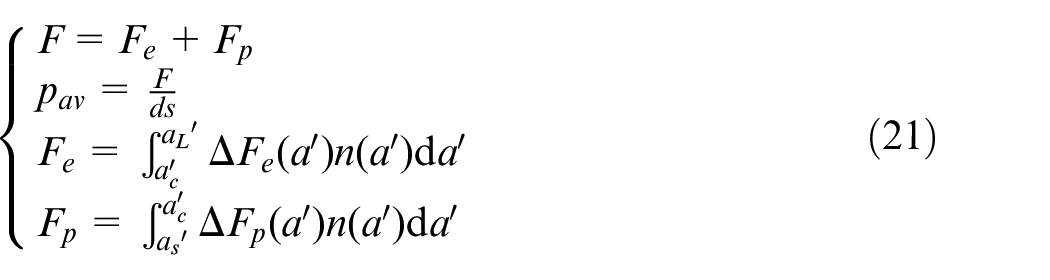
where,
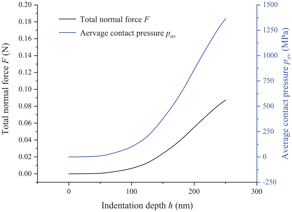
Total normal force and average contact pressure on the micro-contact region.
The distribution of the thickness of lubricant film according to the isothermal elastohydrodynamic lubrication theory 33 is formulated as,
where,
The total normal force
When the normal contact force at the point A is

The total normal force
Modeling of the wear distribution of screw raceway
The wear of the raceway is generally produced in the low-speed operation condition, and the temperature rise of the ball screws is small. The small temperature rise has little effect on preload degradation. 34 Therefore, the temperature of ball screws is not considered in the wear distribution model. The schematic diagram of the raceway wear strip is depicted in Figure 2(c). The wear volume is calculated separately within each micro-contact region, and the wear volume of each micro-contact region is accumulated in the tangential direction of the helix track of the raceway. The wear volume of every wear strip is calculated by the wear volume of each micro-contact region accumulated in the tangential direction of the helix track of the raceway. The total wear volume at each wear strip is determined by the wear volume of one ball multiplied by the number of balls. It is distributed on the entire working raceway to obtain the distribution of the wear depth of the raceway.
The wear volume of an asperity is expressed as,
The normal indentation depth of the largest wear asperity is denoted by
where,
Therefore, the wear volume of an asperity in a unit time and the wear speed are given by
The wear volume of the rough fractal surface in a unit time and in a unit area, the wear rate, is obtained as,
The wear rate

The wear speed in different wear strips of raceway can be determined by the wear speed of each micro-contact region accumulated in the tangential direction of the helix track of the raceway.
The distribution of the wear depth of the raceway is determined as,
where,
Experiments and verification
To validate the correctness of the wear distribution model, the friction torques and raceway profiles of ball screws were measured. To improve the efficiency of experiments, the three-level step-stress accelerated degradation test was designed and implemented.
The three-level step-stress accelerated degradation test
Experimental procedures
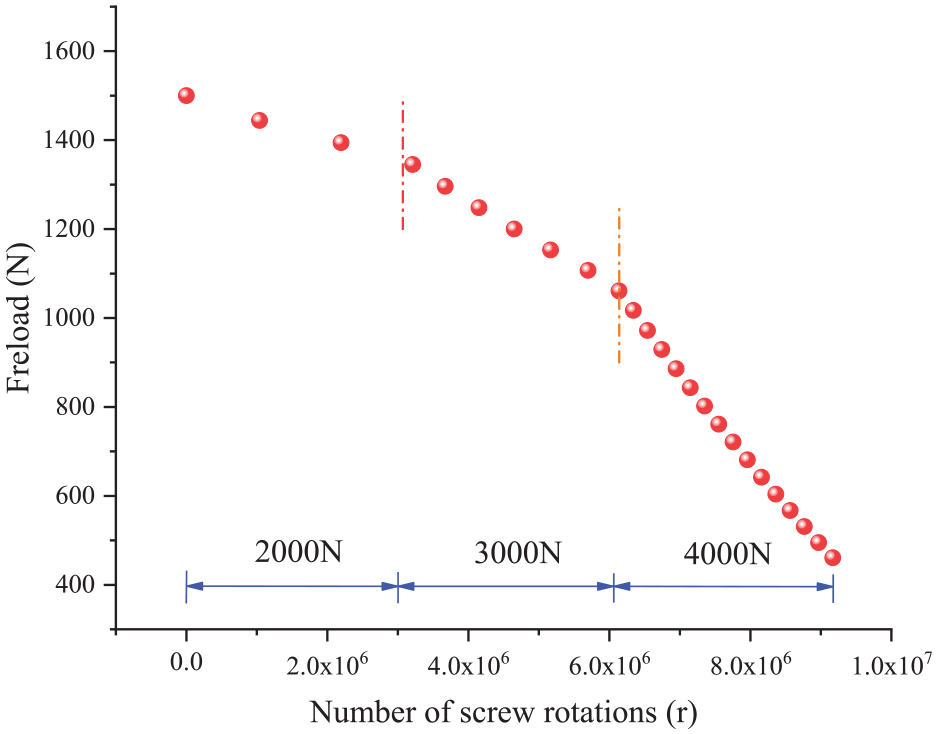
The experimental procedure is shown in Figure 7. There were two operational modes of the ball screws: loading mode and testing mode. In the loading mode, the main nut could drive the table load by the bidirectional cylinder to move with reciprocating motion, and the auxiliary nut moved with the table. The axial working load was stepped in three levels: 2000, 3000, and 4000 N. In the testing mode, the auxiliary nut could drive the table and the tension-compression sensor was mounted on the main nut by the dowel bar. Friction torque with no axial working load was measured every 4.8 × 10⁴ r under the screw speed of 10/3π rad/s.
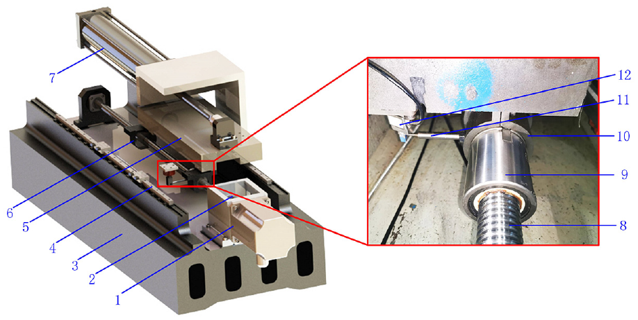
Experimental setup of ball screws. 1. Motor. 2. Coupling. 3. Base. 4. Guideway. 5. Table. 6. Auxiliary nut. 7. Bidirectional cylinder. 8. Screw. 9. Main nut. 10. Clamping device. 11. Dowel bar. 12. Tension-compression sensor.
The results of experiments
The preload in the proposed model was modified when the wear depth of screw raceway increased every 0.1 μm according to equation (2). Experimentally measured friction torques of the ball screws were compared with the results of the proposed model (Figure 8). It is noteworthy that the degradation curves of friction torques of the two ball screw samples were relatively clear with the progression of the test. The friction torques of the two samples significantly decreased under the first level of the axial working load in the initial wear stage, which could not accurately indicate the wearing of the raceway. The degradation curves of the measured friction torques of the two samples under the second level of the axial working load were in good agreement with the numerical results in the steady wear stage. Under the third level of the axial working load, the degradation curve of measured friction torque of sample 1 was in good consistency with the numerical results, while the degradation curve of measured friction torque of sample 2 slightly deviated. Consequently, except for the initial wear stage under the first level of the axial working load, the good agreement of the experimental friction torque of a ball screw with the numerical results confirmed the correctness of the wear distribution model of ball screws.
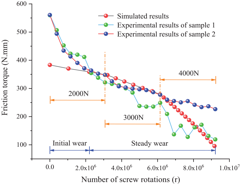
Comparison of the experimentally measured friction torques of the ball screws with the numerical results.
When the preload

where,
Determination of the fractal parameters
The topographic characteristics of the worn screw raceway are studied at the end of the experiment. As the degradation curve of friction torque of sample 1 was in good agreement with the numerical results, the worn screw of sample 1 was cut into shorter pieces by a wire cutting machine. The topographic characteristics on the initial raceway and worn raceway were measured by a white light interferometer (WYKO-NT1100DE1), as shown in Figure 9(a). The measurement of topographic characteristics is illustrated in Figure 9(b). The measured profiles were dealt with the angle modified to be in good agreement with the standard profile (Figure 10(a)) to ensure the measured angle accuracy (Figure 9(a)). The modification of surface profiles was carried out with the radius removal of the normal section on the screw raceway, as depicted in Figure 10(b). The determination of fractal parameters of the initial and worn raceway surface profiles was previously described 35 (Figure 10(c) and (d)). Table 2 shows how the fractal parameters can be determined.
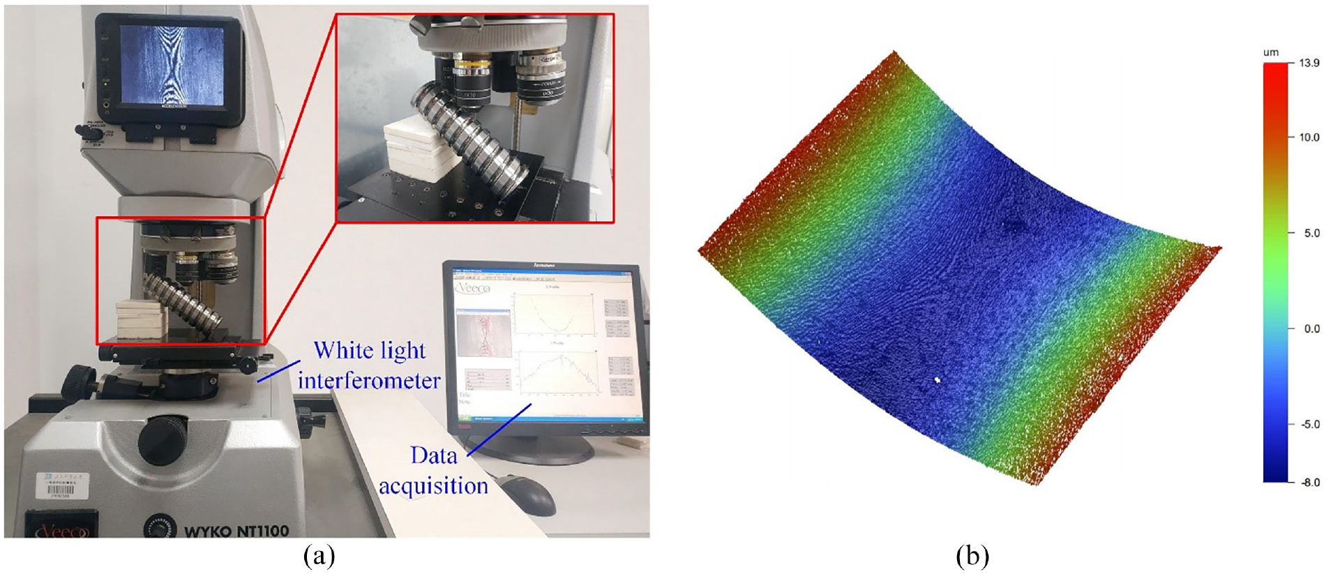
Measurement of the topographic characteristics: (a) experimental setup of raceway and (b) screw-raceway topography.
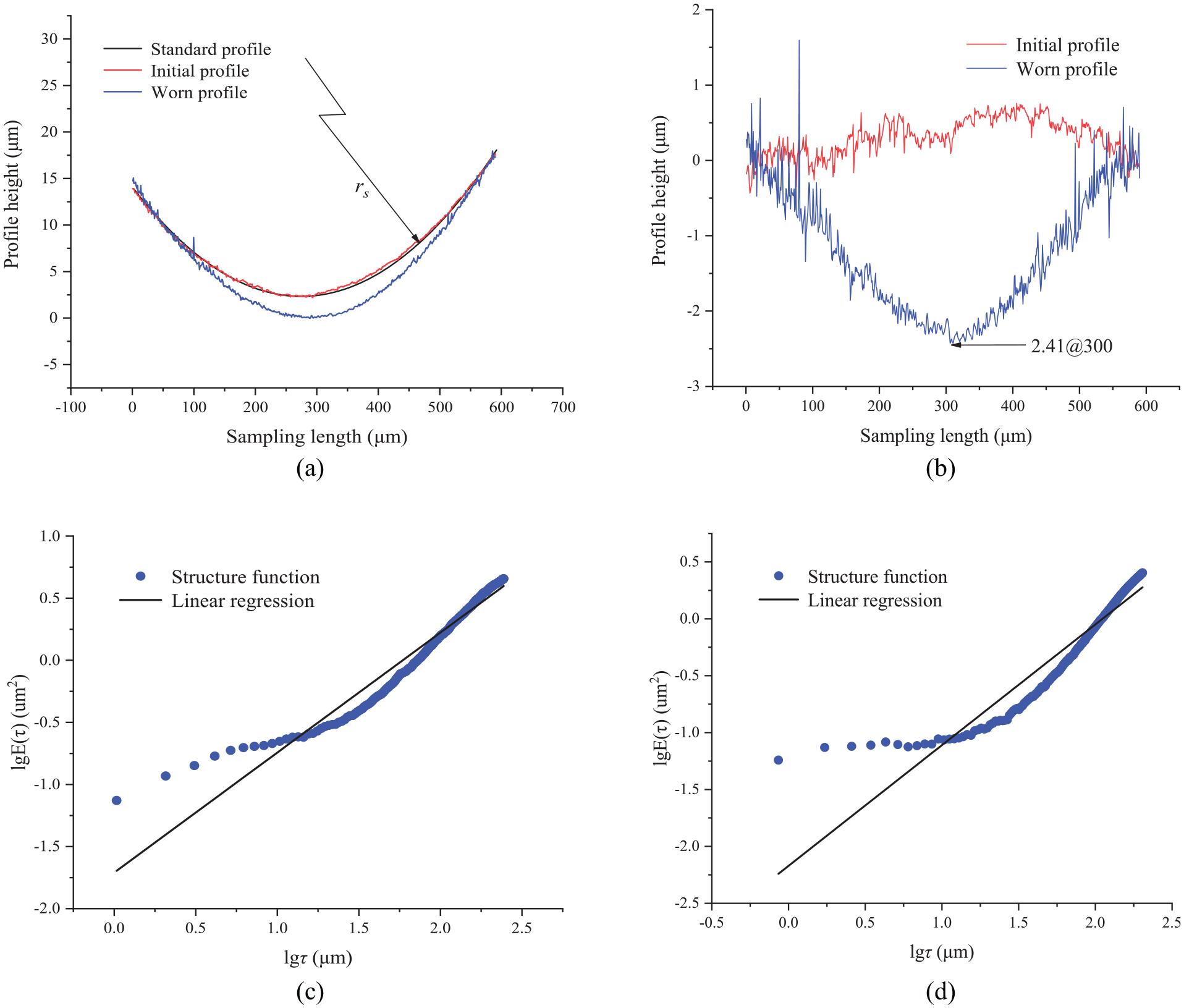
Determination of fractal parameters: (a) comparison of the height of screw-raceway profiles with the angle modified, (b) comparison of the height of screw-raceway profiles with the radius removal, (c) structural function of the initial profile, and (d) structural function of the worn profile.
Comparison of fractal parameters between initial profile and worn profile.
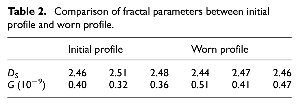
Table 2 shows that the fractal parameters
Discussion
The differences between the degradation curves of friction torques of two ball screw samples, as well as comparing the experimental friction torques with the simulated results, are here discussed. The wear profile of raceway was in a good consistency with the simulated one, confirming the correctness of the wear distribution model. The degradation law of preloading was verified by the proposed model.
Degradation of the friction torque
The degradation curve of friction torque with the stepped load is shown in Figure 8. The friction torques of the two samples significantly decreased with respect to the measured friction torques in the initial wear stage, which resulted from the large roughness of the raceway with the processed ball screws. When the ball screws run for a period of time, the burrs on the grinding raceway surface were worn and were removed by the working ball, and the roughness of raceway decreased to the normal level gradually. The degradation curves of measured friction torques of the two samples under the second level of the axial working load were in good agreement with the numerical results achieved in the stable wear stage. Under the third level of the axial working load, there was an acceptable consistency between the degradation curve of the measured friction torque of sample 1 and the numerical results, whereas the degradation curve of the measured friction torque of sample 2 slightly deviated, which resulted from the instability of the grinding process of ball screws, although the ball screws of two samples from the same batch were processed. Additionally, the existence of a slight difference in material properties of two ball screw samples was normal.
Distribution of the raceway wear depth
The three-level step-stress accelerated degradation test was implemented using the proposed model, and then, the distribution curves of raceway wear depth accumulated by the third level of axial working load could be sequentially achieved. Figure 11(a) shows the similar wear distribution of raceway in third level of the axial working load. The wear depth distribution of raceway sequentially increased with the elevation of the level of the axial working load, while the relationship between the wear depth distribution and axial working load was not linear, which may be related to the fact that the bearing force of lubricant film slightly increased, whereas the asperity support force markedly increased. Additionally, the shape of the contact region on the raceway was an ellipse, whose major axis increased with the elevation of the axial working load.
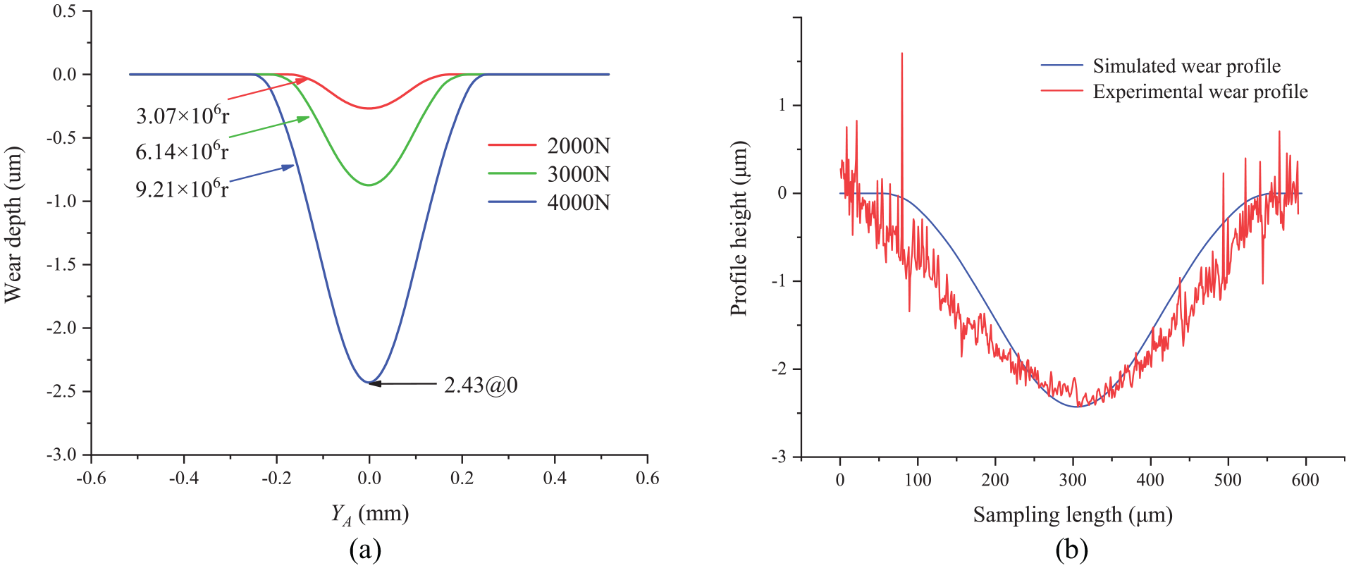
(a) The wear depth distribution of the raceway and (b) comparison of the simulated and experimental wear profiles of the raceway.
As the degradation curve of the friction torque of sample 1 was in good agreement with the numerical results, the profiles on the initial raceway and worn raceway of sample 1 were measured by the white light interferometer. The comparison between the simulated and experimental wear profiles on the screw raceway is shown in Figure 11(b). The largest measured wear depth of the screw raceway was 2.41 μm, while the simulated one was 2.43 μm. The difference between the measured and numerical values was 0.83%. The simulated major axis of the contact ellipse was 512 μm, while the measured one of the contact ellipse was 542 μm. The difference between the measured and the numerical values was 5.54%, which could meet the engineering requirements. The simulated and the measured wear profiles of the raceway were in an acceptable consistency, and the correctness and effectiveness of the wear distribution of ball screws could be verified.
Degradation of the preload
As the axial preloaded gap of double-nut ball screws could be determined by the largest wear depth of the raceway, the degradation curve of preload could be achieved using the proposed model (Figure 12). It is concluded that the degradation of preload accelerates gradually in the three level of loading. This may be related to the mild increase of the bearing force of the lubricant film, in addition to the remarkable elevation of the asperity support force with the increase of axial working load.
Degradation curve of the preload.
Conclusions
The following conclusions could be outlined from the wear distribution of ball screws.
Considering the inhomogeneity of the wear depth distribution on the contact region of the raceway, a wear distribution model was proposed, and the wear profile and wear process of the raceway could be accurately determined to predict the preload degradation of ball screws.
The contact stress distribution and the relative sliding velocity distribution on the contact region could be determined using the kinematics and force balance analyses, which were substituted in the wear distribution model, and the wear profile of the raceway could be achieved.
According to the three-level step-stress accelerated degradation test, the good agreement between the degradation curve of the experimental friction torque and the wear profile of the raceway of ball screws with the simulated results confirmed the correctness of the proposed model.
Due to the wear of the raceway was generally produced in the accelerated operation conditions, the future study in the next stage is the influence of accelerated operation conditions on the raceway wear and preload degradation of the double-nut ball screws.
Footnotes
Declaration of conflicting interests
The author(s) declared no potential conflicts of interest with respect to the research, authorship, and/or publication of this article.
Funding
The author(s) disclosed receipt of the following financial support for the research, authorship, and/or publication of this article: This study was financially supported by the National Natural Science Foundation of China (Grant Nos. 51975020, 51575014, and 5187 5008), Beijing Municipal Natural Science Foundation (Grant No. 3202005), and the International Research Cooperation Seed Fund of Beijing University of Technology (Grant No. 2021A10).