
Abstract
This review presents a techno-economic analysis of microbial fuel cells (MFCs) in the domain of generating sustainable energy and treating wastewater with the aim of attracting investors through research and development for residential and commercial applications. The operation principles and various MFC types, along with their advantages and disadvantages, are thoroughly considered. The efficiency of various MFC types is considered to present appropriate options for commercial applications. However, large-scale integrations face substantial financial limitations owing to the reluctance of investors. This review explores the cost-benefit balance associated with the operation of an MFC system. For encouraging investors, different cost variables, such as the initial investment, operating costs, potential electricity generation, and waste treatment capacity, are thoroughly considered. These variables are placed on the spectrum of a cost-benefit analysis to vitalize the economic feasibility of the MFC technology in various scenarios, considering an order of financial variables. MFC development at an optimized cost is the pivotal pre-requisite to secure a competitive advantage over conventional sources of energy with carbon emissions. Thus, this study is expected to prompt decision-makers to adopt the MFC technology at the commercial level.
Introduction
The present world increasingly depends on the generation of electricity to power industries, houses, cars, and gadgets; thus, electric power must be supplied continuously. To supply this growing demand, an ample generation capacity must be installed using economic sources that comply with carbon emission standards. In search of sustainable sources, humans have discovered and invented various means of energy generation such as hydel, solar, and wind power generation methods, and look forward to biological-based energy generation, such as that from biomass, biogas, bioethanol, biohydrogen, and microbes. The main concern for any energy generation source is the availability of input fuel to produce electricity. Microbial fuel cells (MFCs) use an excellent and sustainable technology among other renewable sources of interest because they consume organic and inorganic waste for electricity generation; thus, they have continuously developed in recent decades (Munoz-Cupa et al., 2021). This study aimed to elucidate the use of MFCs as an emerging inexpensive electricity source.
MFCs function as bacterial chemical reactors that generate electricity through the biodegradation of organic substances, wherein a microbial substrate is added as a catalyst. That is, bioelectrochemical devices transform organic materials into electrical energy using microorganisms. Exploiting the metabolic activities of bacteria provides a sustainable and ecologically benign alternative for power generation (Cristiani et al., 2019). Various substrates, including acetate and glucose, were employed under laboratory conditions to identify the behavior and structure of the electrode and membrane materials (Ma et al., 2023). In 2004, wastewater was used as an alternative and cheap option, where the energy consumed for aeration and treatment could be reduced. Moreover, sludge production can be reduced by implementing MFCs compared to conventional treatments and digesters. They are less sensitive to temperature variations, and their energy consumption is minimal for aeration. Several studies have explained different components and working principles of MFCs, including biofilms, electrodes, cathodes, anodes, membranes, mathematical modeling, performance, and affecting variables (Saba et al., 2017).
Because of the rising demand for energy and resulting environmental issues, researchers have focused on developing clean and sustainable energy sources. Various commercially operated renewable technologies, including solar, wind, hydro, biogas, geothermal, and fuel cell technologies, are available as alternatives to fossil fuels. Considering the aforementioned issues and sources, MFCs are considered as a favorable option for generating electricity and simultaneously eradicating pollutants. MFCs still encounter various marketing challenges as competitive energy sources despite extensive developments. Many studies have highlighted technical challenges, including controlling the unstable voltage, improving methods for power generation, robust design for multiple loss mitigation, and voltage reversal detection and prevention. However, commercial decisions are affected by the availability of low-cost materials (Goswami and Mishra, 2018).
Many studies have been conducted to determine the technology that can be deployed for MFCs. Furthermore, apart from the energy and water output, maintenance regimes have been monitored to analyze the anode material, which can be sustained for a longer period. As MFCs are a dual-purpose technology, their benefits have been analyzed using both revenue factors. Various types of sediments were investigated for power generation; accordingly, an MFC-powered rowing float was developed for wastewater treatment. This application enhances the MFC usage (Rago et al., 2017). Many studies have only applied MFCs to wastewater treatment. However, enlarging the reactor size from a few millimeters to thousands of liters remains a challenge. However, the power output remains the capacity-limiting factor with a proportionate increase in the size of MFCs. Similar to other emerging technologies, MFCs encounter scaling-up challenges; thus, they are stuck between the laboratory setups and real-world applications(Cristiani et al., 2019). Real-world applications require chambers of increased size containing electrodes and other modules in a stacked arrangement to generate electricity. Such a large and scalable MFC design must be built using inexpensive materials, including electrodes and membranes, considering the optimal conditions for harvesting a high rate of energy at a certain capacity (Jadhav et al., 2021; Kannan and Donnellan, 2021). The scaling up of this type of simple structures must sufficiently perform for anticipated objectives, that is, power and water, by optimizing the cell array and connecting it in a parallel series (Santoro et al., 2017a).
Therefore, this study aimed to review the present status of MFC research to identify key advances and analyze the obstacles and prospective uses of the MFC technology. The results are presented from a variety of perspectives, including technical perspective, which is typically the domain of engineering specialists, and economic perspective, particularly the financial and market aspects that are considered by investors. Finally, we examine additional variables that may affect the competitiveness of a specific choice. This research is particularly significant for policymakers who have several tools at their disposal to accelerate changes and provide equitable possibilities for hydrogen as a fuel alternative using MFC systems. Moreover, this framework helps select analysis parameters and interpret the outcomes; however, these concerns are interconnected, and a holistic strategy is required (Rozene et al., 2021; Ummalyma and Bhaskar, 2023).
This integrated approach allows the assessment of the relative effects of various technical improvements on competitiveness rather than only the capital cost (CC) or performance and the tradeoffs necessary between technical, economic, and comparative concerns. The cost model elaborates on the quantitative assessment of activities, along with a sensitivity analysis varying from pessimistic to optimistic scenarios; accordingly, the influence of parameters is converted into economic terms.
This review elucidates the diverse aspects of MFCs for a fundamental understanding to support techno-economic evaluation, such as the design, mechanism, evaluation, considerations for energy generation, voltage reversal phenomena, stacking, and enhancement of the MFC performance. The broad areas investigated are as follows:
MFC development; Understanding MFC designs and operations; Analyzing MFC working principles; Identifying approaches used to enhance the performance of MFCs.
Moreover, detailed reports on economic feasibility and the required conditions for applying MFCs as smart microgrids have rarely been discussed in previous studies. The economic viability of MFCs is a key factor in their widespread acceptance. The wastewater treatment plant used for MFCs generates power similar to other fuel cells; however, the MFC differs in that the feedstock is widely available in all areas, from small villages to big cities. These assessments consider CCs associated with building MFC reactors, electrode materials, and supporting infrastructure, as well as the operating costs associated with maintaining and monitoring the performance of MFCs. Moreover, the potential benefits of MFCs, particularly the low organic waste disposal costs and revenue generation from energy production, were considered. The cost-benefit analysis (CBA) sheds light on the economic viability and benefits of the MFC technology. There are limited studies on MFCs; the cost components are difficult to measure owing to the lack of commercialization, and the available structures are prototypes at the laboratory level. Therefore, future research and development in the structure of MFCs and cost-cutting measures are required to improve the economic viability of MFCs and encourage their wider use as a renewable energy source (Goli et al., 2019).
The essence of this review is as follows:
Promoting the available stacked design using a fundamental principle; Use of inexpensive and efficient material; Analyzing the financial viability of MFCs at a certain capacity.
The remainder of this article is organized as follows. The second section describes the basic MFC concept and principle, operations, reactor design, and applications, along with the advantages and disadvantages of MFCs. The third section illustrates the economic feasibility and sensitivity analysis, followed by the scaling-up issues at a commercial level. The fourth section examines the prospects under discussion. Finally, the fifth section draws the conclusions. Figure 1 depicts the framework of this study.
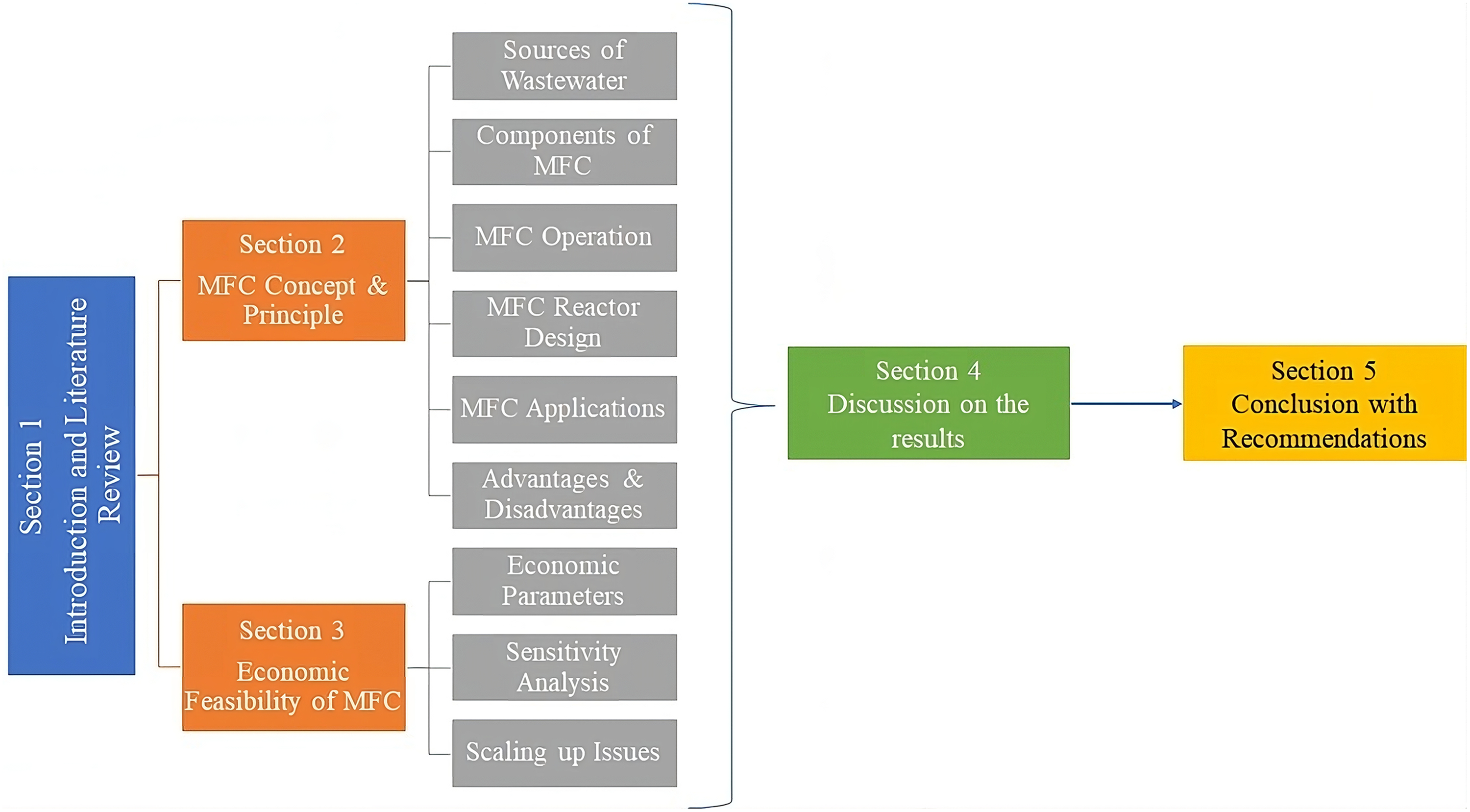
Framework of this study. MFC: microbial fuel cell.
MFC concept and principle
MFCs operate based on a combination of the biological and chemical scientific disciplines. Bio-electrical chemicals operate in a systematic manner, wherein microorganisms convert chemical energy into electrical energy. This catalytic reaction is mimicked by bacterial interactions. As shown in Figure 2, cellular respiration of the microbes converts the nutrients of the substrate into adenosine triphosphate as a fuel for cellular activity based on exothermic redox reactions. The bacteria in matter convert the substrate into protons and electrons and generate power by running through a circuit (Dannys et al., 2016).

Microbes in microbial fuel cell.
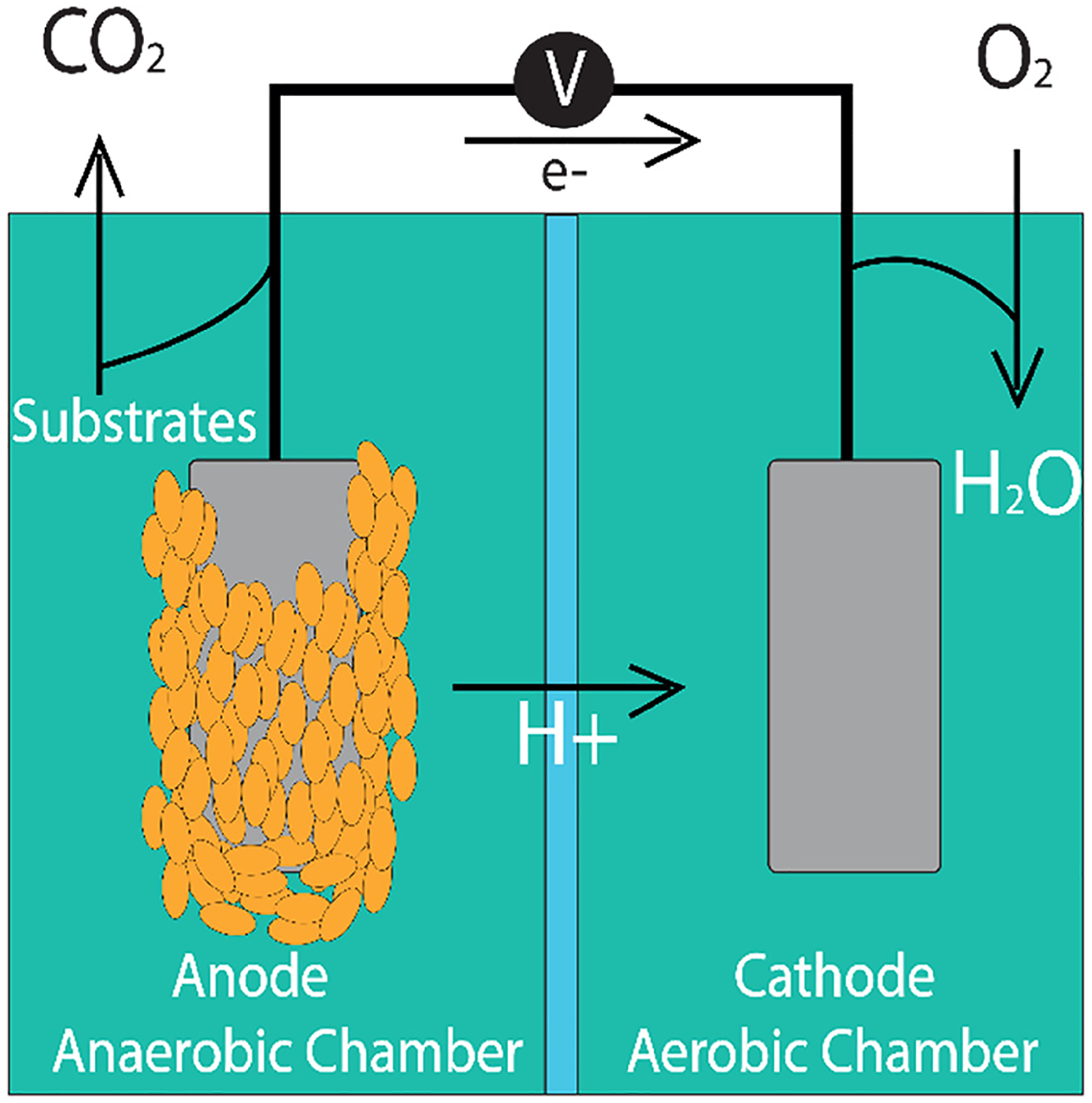
The interaction of microbes creates hydrogen and electrical charges with essential ingredients from familiar sources, such as organic waste and wastewater treatment, as depicted in Figure 3. This process generates electricity and clean water. Furthermore, microbes provide biofuel, hydrogen, bioplastics, and biochemicals and facilitate metal recovery by introducing additional filtering processes (Pandit et al., 2017).

Concept of microbial fuel cell.
The occurrence of different chemical reactions depends on the organic material used. However, the basic principles of all reactions are identical. The oxidation process on the anode side is called the anodic reaction, as expressed in equation (1), and the reduction process on the cathode side is called the cathodic reaction, as expressed in equation (2) (Pandit et al., 2017).


Sources of wastewater/feedstock
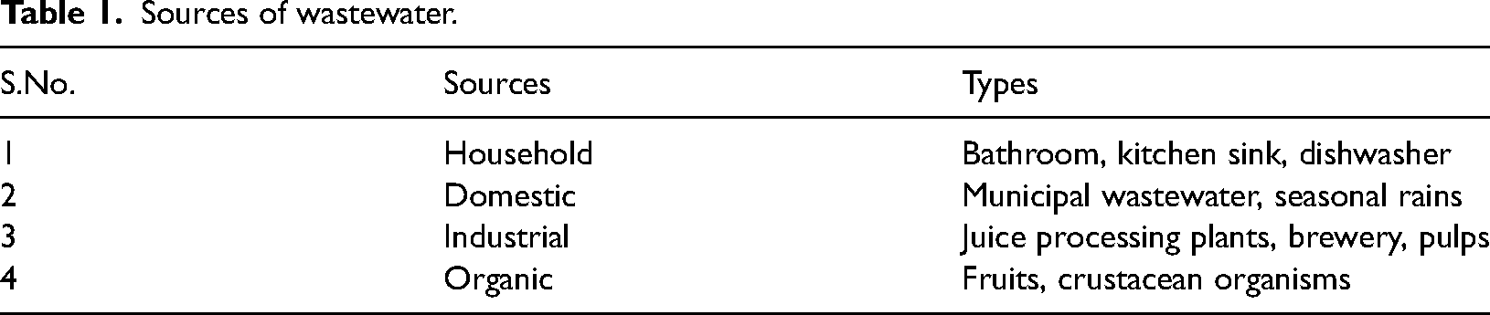
Feedstock is the main component for the operation of any power-generating unit and should have a sustainable supply chain. Fortunately, MFCs operate on wastewater, which is available in all areas, particularly in urban suburbs. Wastewater is collected and treated in all developed countries, whereas developing countries are improving water treatment solutions. Table 1 lists the wastewater sources that were identified by Lal (2013). The regular supply of feedstock must be considered; therefore, apart from a sustainable energy source, a robust supply chain system with adequate nutrients through a proper source of wastewater mix is required (Goli and Keshavarz, 2022; Goli and Mohammadi, 2022).
Sources of wastewater.
Components of MFCs
An MFC comprises six components that are essential for completing the process and producing the desired output (Rashid et al., 2021), as shown in Figure 4.
An anode is present in the anodic chamber, where it interacts with the microbes and possesses conductivity and biocompatibility properties, which are stable with the substrate and chemical reaction. Cathode formation depends on the type of MFC; however, it consolidates the electrons and protons that interact with oxygen and convert it into water. Platinum (Pt) is typically used as a catalyst. The exchange membrane joins the anode and cathode chambers, where protons flow through the membrane and combine with electrons on the side. They are generally composed of NAFION or ULTREX. The electrons travel through an electrical circuit to power the load. Microbes, also known as “geobacteraceae and bacteroides,” are anaerobic organisms that grow without oxygen. Substrates provide energy to bacterial cells and consist of wastewater from different sources, such as domestic, industrial, commercial, and agricultural sources. Substrates contain organic substrate lime proteins, volatile acids, carbohydrates, and cellulose.
Microbial fuel cell components.
MFC operation
The MFC operation can be divided into two segments. The first segment handles wastewater processing at different stages to obtain an appropriate feedstock. The second segment manages the MFC component assembly (Loga and Rega, 2023).
Wastewater treatment is essential to obtain a smooth fluid that is free from major particles and is made available in large quantities to achieve economies of scale. Treatment depends on the source and characteristics of wastewater and desirable outputs, such as storage for reuse or release into rivers or streams. Solid and organic materials are primarily removed from wastewater, followed by other organic and chemical materials (Wang et al., 2022).
The minimum required treatment involves removing suspended solids and organic materials to a smaller or larger degree. Figure 5 illustrates the main stages of installation. With an appropriate combination of the main components, the required degree of treatment can be achieved each time (Tsekouras et al., 2022). The following stages were included:
The preliminary stage involves removing inorganic materials from waste, that is, coarse solids and grit; it is primarily accomplished through physical procedures, that is, screens and grit chambers. The primary treatment stage includes settlers, where partial removal of organic materials, such as settleable, suspended, and floating solids, is achieved using physical/physicochemical procedures. The secondary treatment stage consists of biological procedures. With the use of a biological reactor and final settler, approximately complete removal of suspended materials is attained, including the removal of a large part of the soluble organic substances. Moreover, phosphorous/nitrogen removal can occur in some instances. The tertiary treatment stage consists of additional biological procedures to remove nutrient components (nitrogen and phosphorous), if it does not happen at earlier stages. The synthesis of the individual units varies with the waste being treated. These units are refineries or membrane installations. The disinfection stage aims to eliminate all pathogens, which is applied when contamination poses a risk to the final disposal (irrigation and swimming facilities). The sludge treatment stage appropriately treats the sludge retrieved from the previous four stages to acquire a form appropriate for easy and safe disposal of byproducts. This stage typically comprises thickeners, digesters, and dewatering systems.
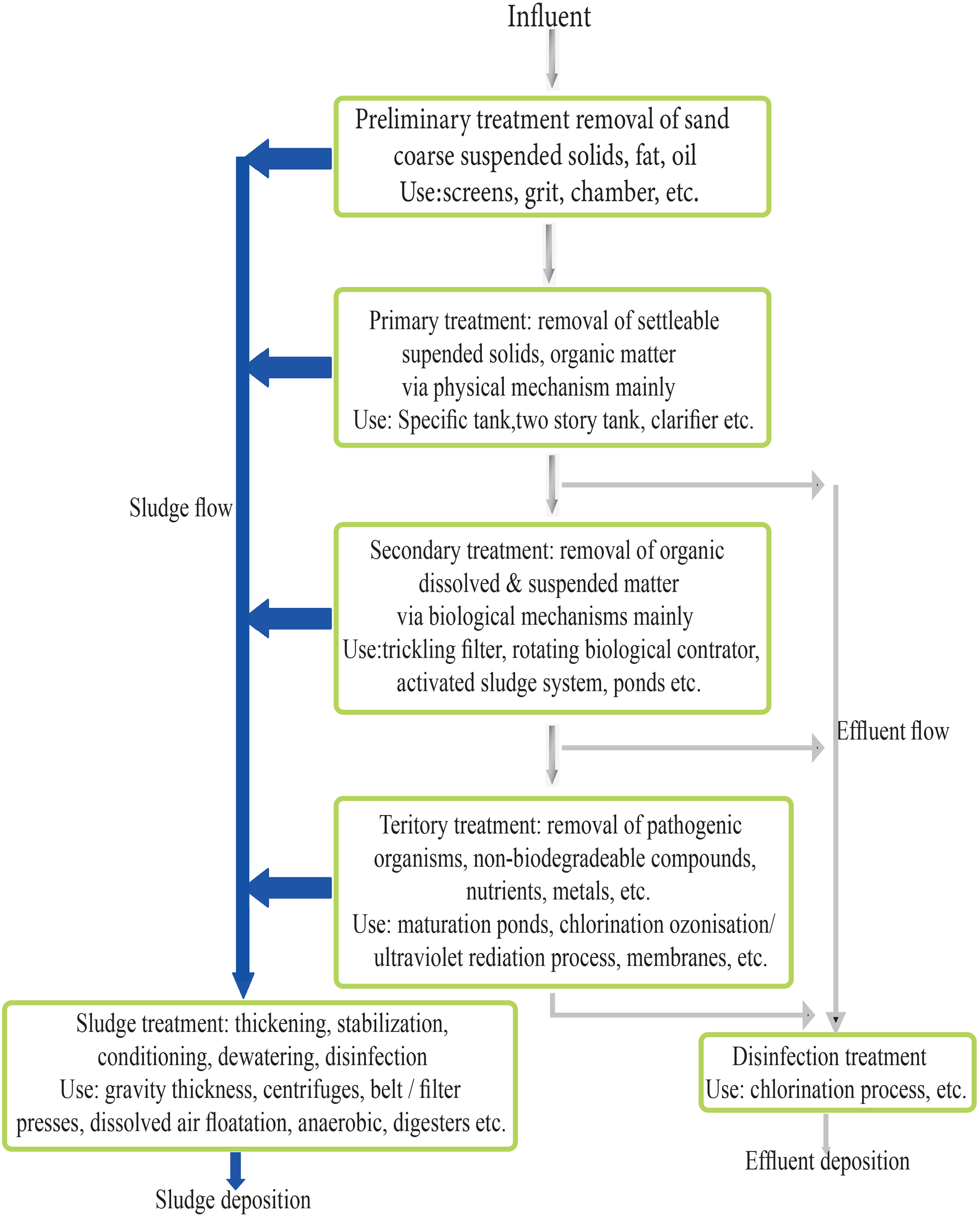
Flowchart of a biological treatment installation (Tsekouras et al., 2022).
MFC reactor designs
Reactor design is vital from the efficiency and cost perspectives. Therefore, many diverse types of MFCs have been developed to improve the power output. Configurations of different components, types, structures, and dimensions are considered to achieve an optimal result. The success of various configurations is under research and development; however, researchers have advocated different types of designs, weighing their advantages and disadvantages, as listed in Table 2 (Murugesu et al., 2022).
Pros and cons of MFC types.
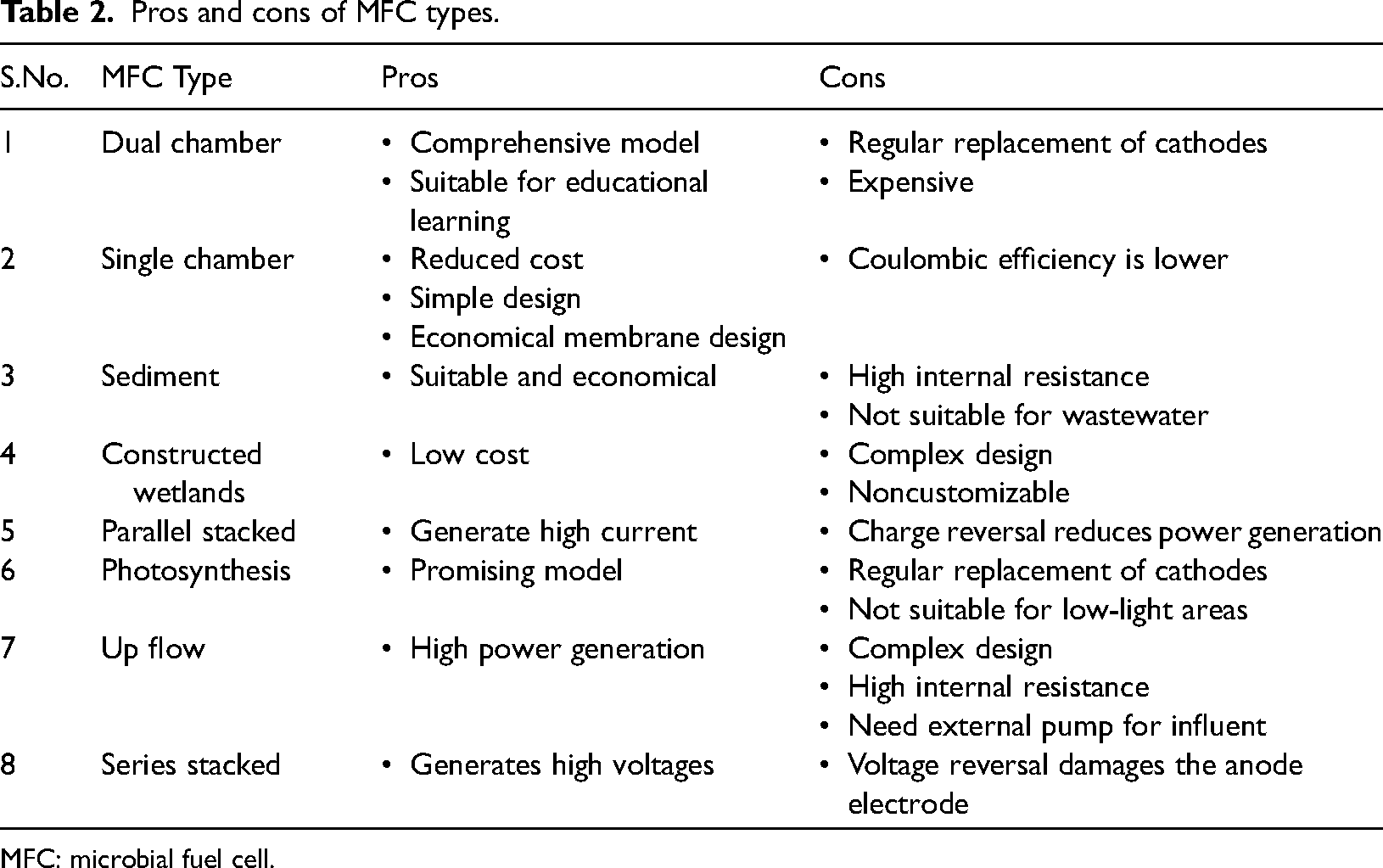
MFC: microbial fuel cell.
Dual chamber MFC
It consists of anodic and cathodic compartments that are separated by a membrane. This model was introduced to reduce costs, and it was modified for a single chamber. Several types of dual chamber MFCs (DCMFCs) are available, and H-type is a typical design. It has two chambers connected to a membrane bridge, as shown in Figure 6. The anodic chamber produces electrons via oxidation, whereas clean water is produced in the cathodic chamber via reduction. This comprehensive design is used for educational purposes instead of commercial applications, because it is an expensive solution (Obileke et al., 2021).
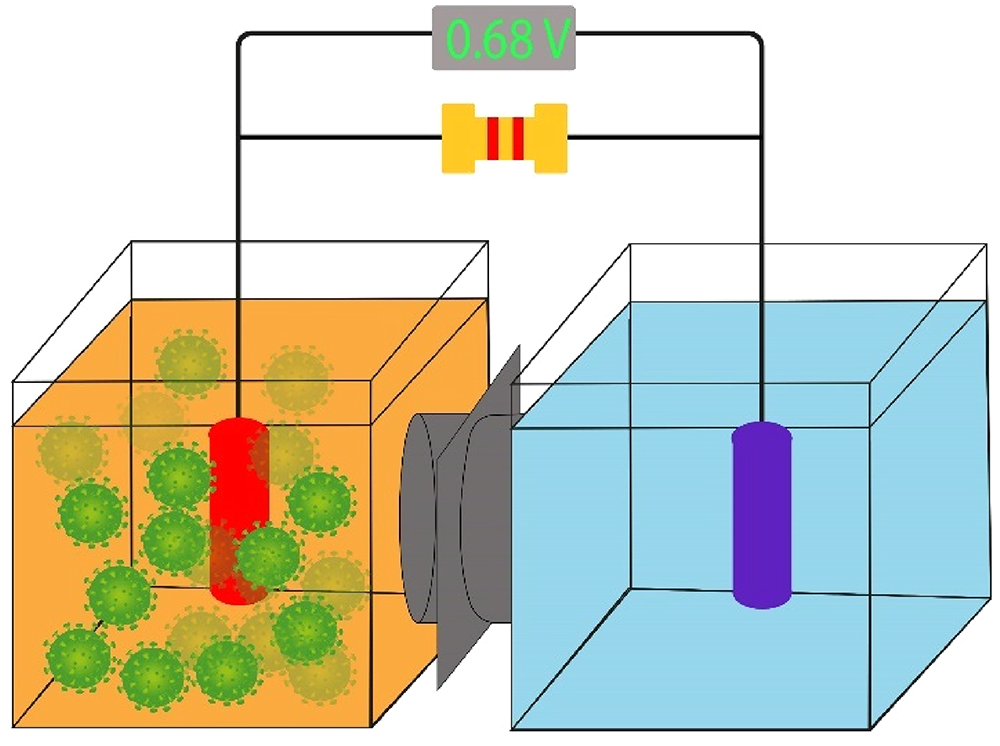
Dual chamber microbial fuel cell.
Single chamber MFC
Single chamber MFCs (SCMFCs) are a modified design of DCMFCs that connect the cathode with direct air to capture free oxygen, thereby reducing costs. In this configuration, the cathodic chamber is removed, and other components, including the cathode, optional membrane, mediators, and microorganisms, remain intact, as shown in Figure 7. SCMFCs are low-cost and simple MFCs. The cost can be further reduced using a membrane-less SCMFC. However, its reduced cost affects the coulombic efficiency owing to the anodic oxygen diffusion (Sakr et al., 2021).
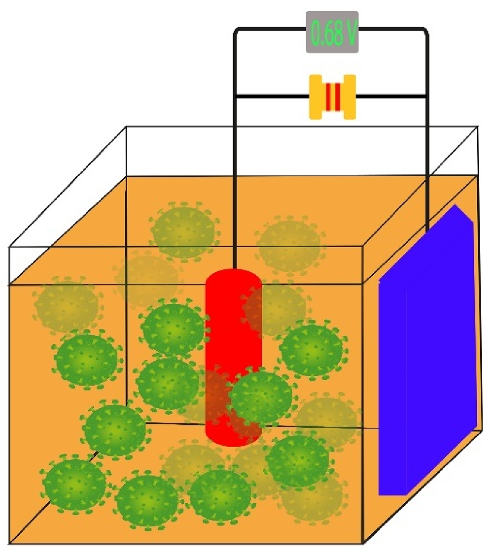
Single chamber microbial fuel cell.
Sediment MFC
This type of MFC is based on existing natural ecosystems of sediment and water. In this configuration, anode is placed in the sediment, cathode is on the waterside, and no membrane is used. A copper wire is used to complete the circuit by connecting the anode and cathode, as shown in Figure 8. Earlier designs used a cylindrical tube, graphite granules, and a graphite rod as the anode and cathode. Consequently, sediment MFC (SMFC) is a cost-effective design; however, it does not provide wastewater treatment owing to its internal resistance (Thomas et al., 2013).
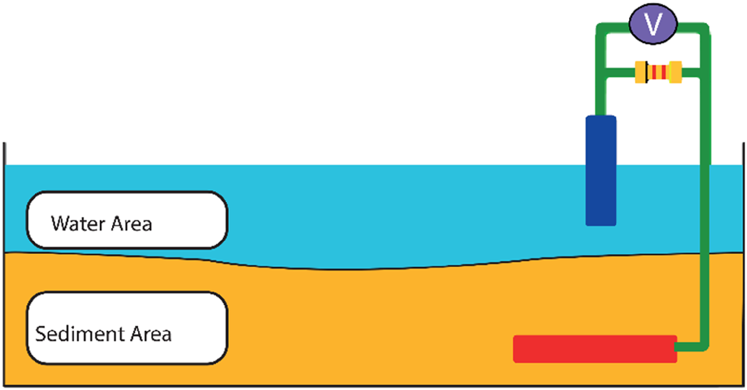
Sediment microbial fuel cell.
Constructed wetland MFC
A constructed wetland MFC (CWMFC) combines the double chamber and photosynthesis designs, consisting of anode and cathode chambers parted with a glass wool, as shown in Figure 9. The configuration is arrayed vertically, and the anode chamber is placed at the bottom and sealed with epoxy. The cathode chamber is at the top and opens into the air. Use of glass instead of proton exchange membrane (PEMs) is cost-effective (Wang et al., 2020).
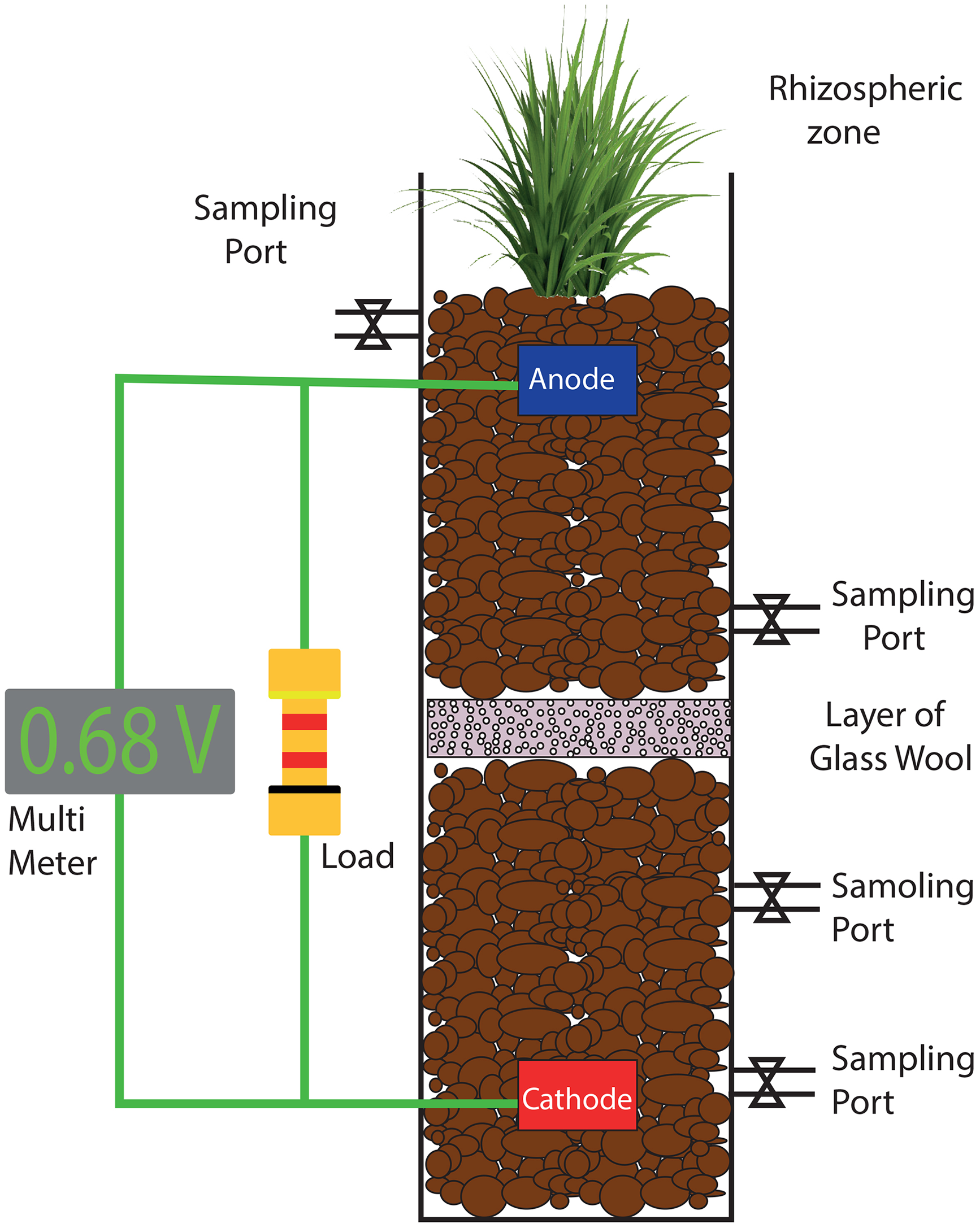
Constructed wetland microbial fuel cell.
Parallel-stacked MFC
In parallel-stacked MFCs (PSMFCs), anodes and cathodes are connected in series with adjacent anodes and cathodes in the chambers to accumulate current in the system, as shown in Figure 10. Previous studies have analyzed configurations in parallel and series stacking and reported that the parallel configuration produced a high current and series stacking produced a high voltage (Yadav et al., 2012).
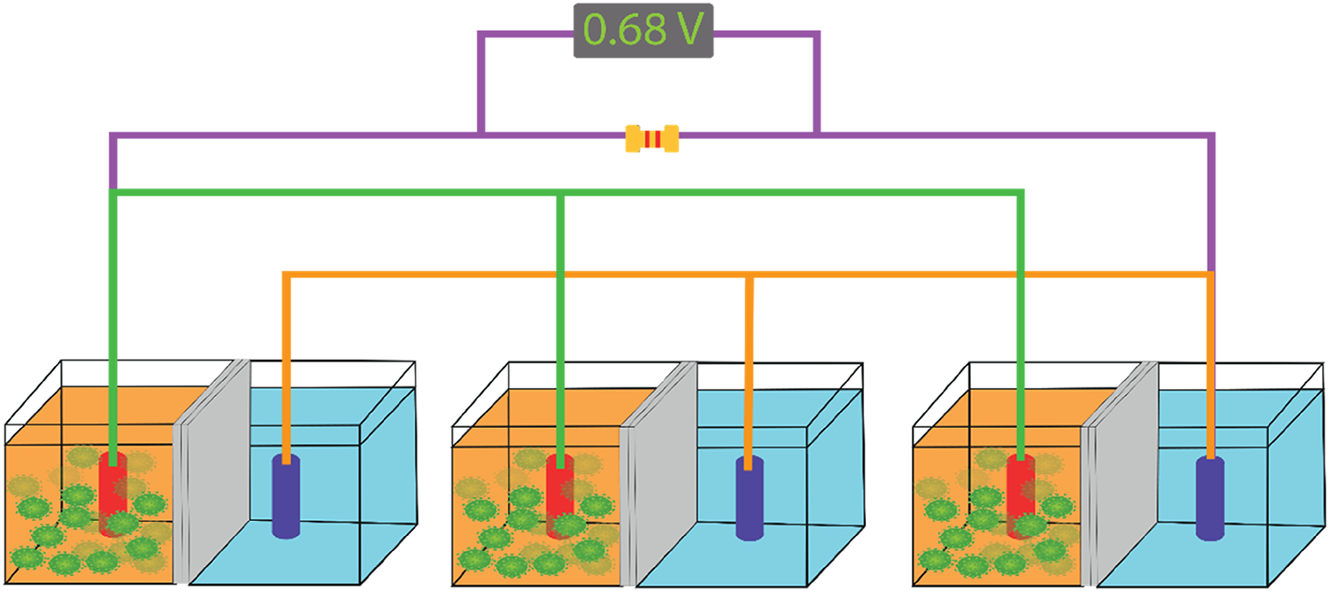
Parallel-stacked microbial fuel cell.
Series-stacked MFC
Series-stacked MFC (SSMFC) is a basic concept based on multiple dry cells to increase the voltage, as depicted in Figure 11. It consists of two single chambers of anodes and cathodes connected by a graphite plate. The anode and cathode are composed of carbon paper and Pt-coated carbon, respectively (Thung et al., 2015).
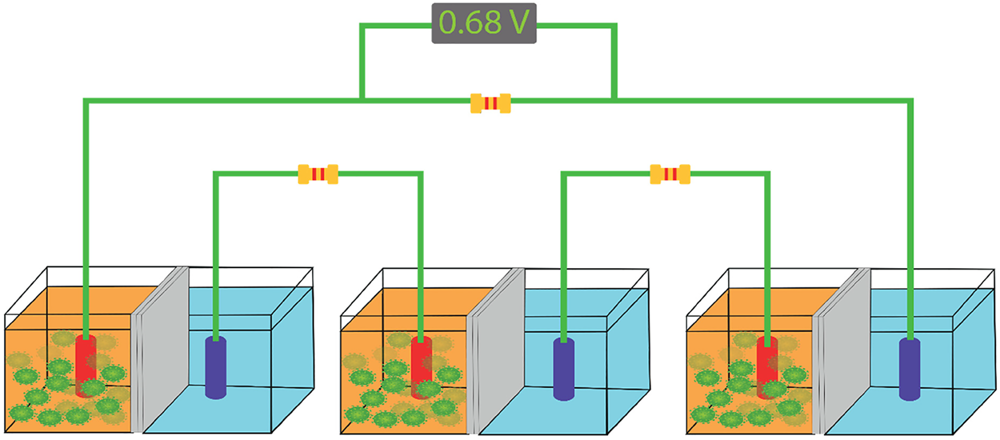
Series-stacked microbial fuel cell.
Photosynthetic MFC
Photosynthetic MFCs (PMFCs) employ bacteria that produce electricity from solar energy. The plant is used as an alga in the anode side chamber, called PMFC, as shown in Figure 12. The three-compartment MFC design consisted of microalgae exposed to light through an LED strip, which provides an influent to the anode chamber. This design is comparable to the double-chamber design considering the power generation and cost-effectiveness (Aelterman et al., 2006).

Photosynthetic microbial fuel cell.
Up-flow MFC
In up-flow MFCs (UFMFCs), the cylindrical chambers are connected vertically, wherein the cathodic chamber resides at the top, and the anodic chamber lies at the bottom. The PEM is used to avoid gas bubble accumulation in the middle at an angle of 15°, as shown in Figure 13. The effluent is released in the middle of the anodic chamber and then pumped to the bottom. The cathodic chamber is supplied with air from the top, and the anode and cathode are connected using a copper wire to complete the circuit (Oh and Logan, 2007).
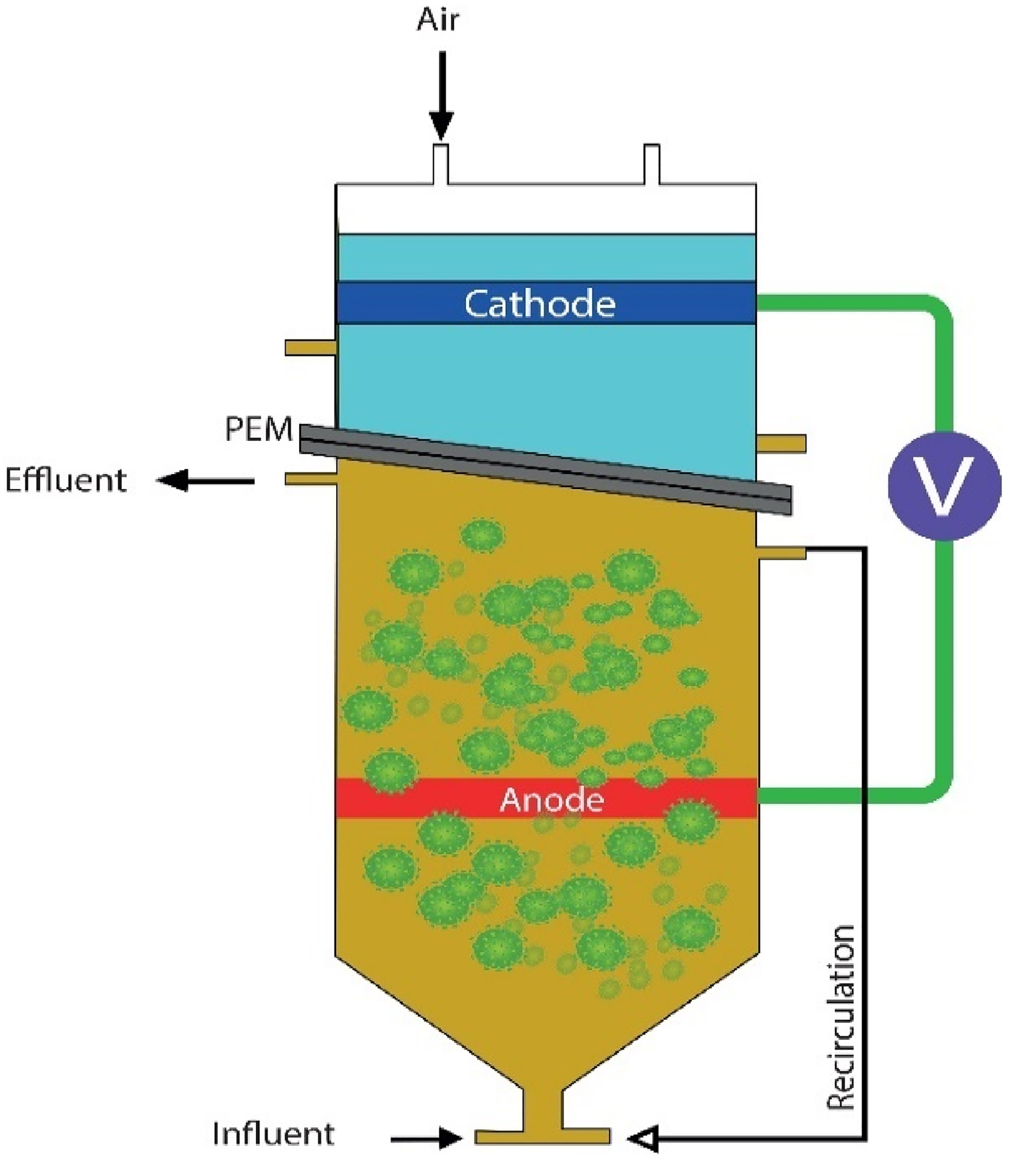
Up-flow microbial fuel cell.
Some studies have used gravel as a separator, creating a membrane-free MFC. Carbon-felt and platinum-coated carbon papers are used as anodes. The cathode is composed of carbon flakes. The influent is pumped from the bottom of the anodic chamber to the cathodic chamber, and the anode and cathode are connected using a copper wire. This design reduces the power density owing to internal resistance and is complex (Nayak and Ghosh, 2019).
Applications
The deployment of MFCs primarily harnesses electricity; however, it also produces byproducts that can be used for other processes and manufacturing of various products. The input and output components are illustrated in Figure 14.
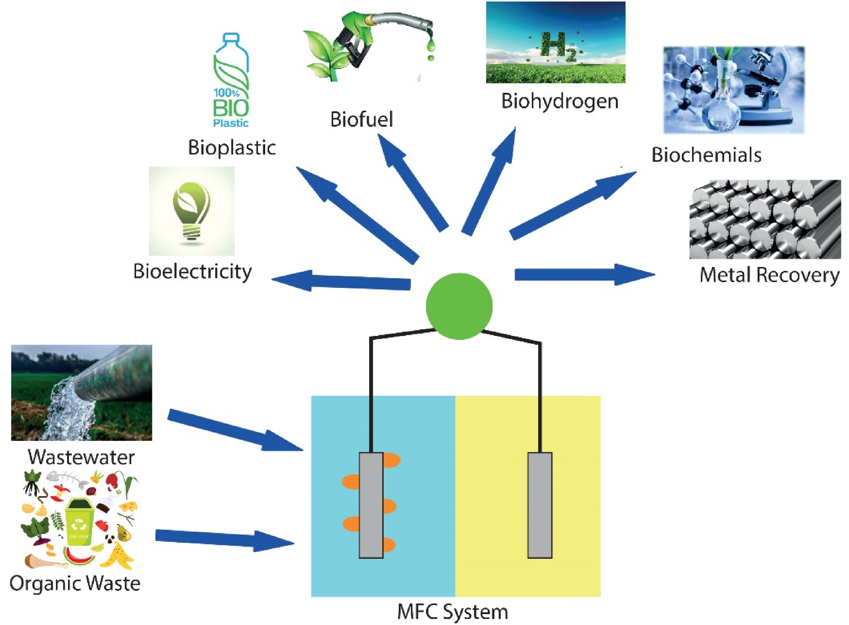
MFC input and production. MFC: microbial fuel cell.
MFCs have been tested using different portable power sources, including wireless sensors, mobile phones, oceanographic equipment, microcomputers, thermosensors, meteorological buoys, water quality biosensors, and microrobots.
MFCs are extremely effective in utilizing wastewater and provide a sustainable treatment to reuse that water. Thus, it simultaneously harvests electricity and sources of clean water, which can be used for various purposes, such as agriculture, industry, and municipal uses. Many studies have been conducted to increase the power density level of MFCs to be employed for large-scale commercial operations in various disciplines. Currently, high-level power generation is achieved using stackable MFCs (Santoro et al., 2017b).
In addition to wastewater treatment, MFCs are utilized for applications such as bacterial enumeration and biochemical oxygen demand (BOD) biosensors. MFCs are enriched with active bacteria that produce electrical charges for toxicity detection and employed as BOD biosensors. The toxic matter present in wastewater includes lead, chromium (VI), cadmium, arsenic, organophosphorus, mercury, and surfactants that affect the electric current and facilitate the toxicity level detection in the water. Current generation is proportional to the biodegradable waste and toxic concentrations at low-level concentrations. This toxic substance can be monitored in wastewater systems by combining BOD measurements (Daw et al., 2012; Ardakani and Gholikandi, 2020).
The sediment has recently made progress in wetland management, and the current produced during operation can be successfully stored in capacitors and consumed through a power management system in remote sensors. Therefore, SMFCs are used as underwater monitoring devices and are useful for implanting biomedical devices in the human body. SMFCs are miniature and use bloodstream glucose to generate electricity; however, an increasing contamination increases the current generation. In the future, the MFC technology can support the enumeration and detection of microorganisms in food items (Kim, Chang and Gadd, 2007).
Advantages and disadvantages of MFCs
An MFC is a novel source of power generation that offers a unique opportunity to provide added advantages compared to other sources; however, it also has disadvantages. MFCs offer several advantages (Pote et al., 2022).
Advantages of MFCs
Disadvantages of MFC
Despite many advantages, MFCs also carry disadvantages as follows:
Economic feasibility of MFCs
In this study, the economic feasibility of MFCs considering different cost parameters is briefly discussed. A major cost component is the feedstock, which is regarded as the cheapest or cost-free component. The feedstock sources are widely available in all villages, towns, and cities in the form of domestic and industrial wastewaters.
This study provides a systematic evaluation approach for selecting a feasible option, policy, or project among various alternatives based on the incurred costs and reaped benefits. For instance, fuel cells have multiple options for assembling components to achieve a desirable efficiency, and a financial evaluation is required for each design. Thus, technical and economic evaluations must be considered for the selection of an MFC. The economic evaluation is an expensive and time-consuming process. Therefore, Xu et al. (2018) introduced a simplified economic feasibility model to explore and set guidance patterns for future studies.
Economic feasibility encompasses the estimated capital and operating costs along with financial evaluation criteria, such as the Net Present Value (NPV), benefit-to-cost ratio (BCR), internal rate of return (IRR), and discounted payback period (DPP). Because MFCs are not employed in microgrids, the scaled-up capital, operating, and maintenance costs have not been specified univocally. Moreover, the expected long-term useful life is not determined owing to the fumes of the wastewater that deteriorate the metal infrastructure in a short time span; therefore, extensive maintenance is required for an extended period. Epoxy resin layers can be used to protect metals from rust and to avoid high maintenance and replacement costs (Jiang et al., 2023; Savla et al., 2021).
Economic parameters
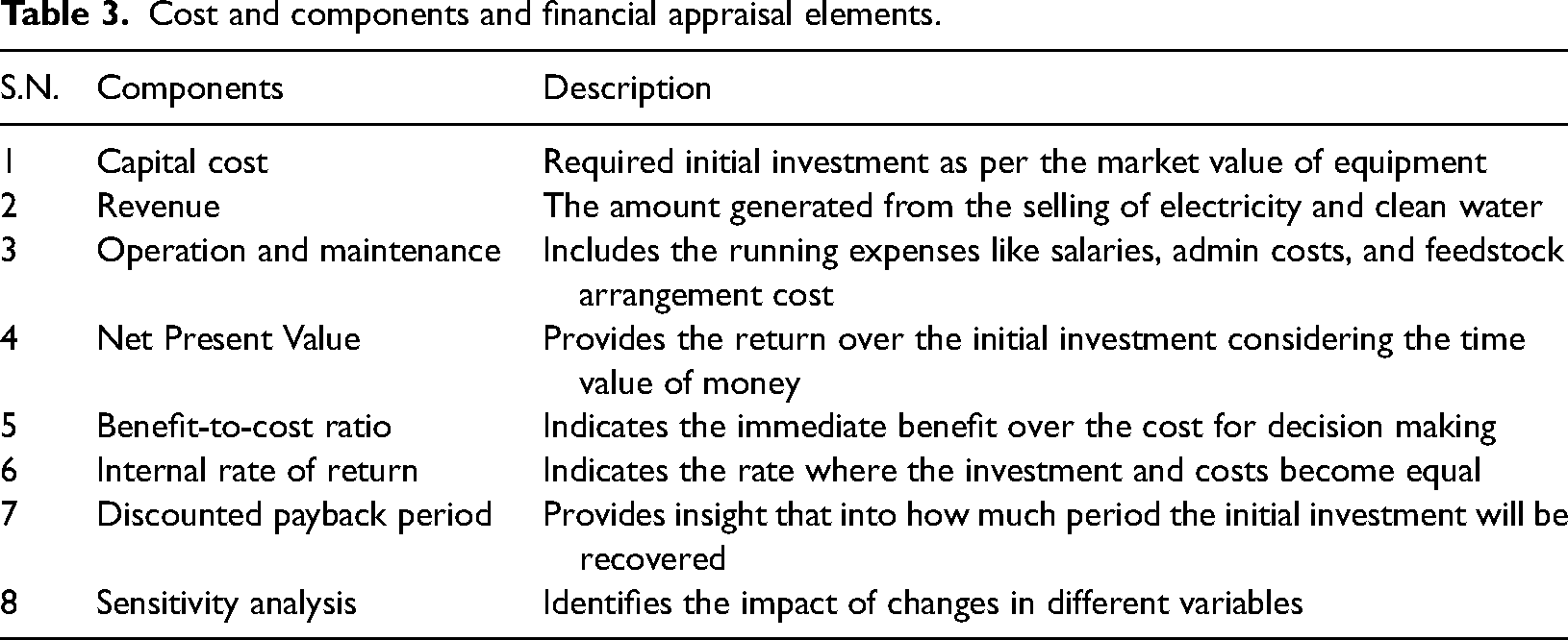
Savla et al. (2021) used an economic evaluation model and presented cost estimates under different cost segments with respect to the treatment capacity, and discussed the next steps accordingly. The presented costs were in Euro, which were converted into USD with a ratio of €1:$1.08 (Trapero et al., 2017). Table 3 summarizes different elements evaluated, which were subsequently elaborated individually to explore the subcomponents and their cost treatments.
Cost and components and financial appraisal elements.
Capital cost
The employment of MFCs in microgrids and at industrial scales requires higher CCs owing to expensive materials. Moreover, CC consists of components such as the cost of electrodes, cathodes, reactors, and wires, depending on the structure of an MFC. Different materials have different characteristics that affect their operating life; most of these materials have a life span of 10 years with a depreciation value of 90%. However, the effective lifespan of membrane is comparatively extremely short (2 years) and has a depreciation value of 50%. Various MFC components can be used after thorough cleaning and recycling, the costs of which can be estimated based on the operating life of the MFC. Furthermore, CC of MFCs is defined as follows:

Materials with high scalability and efficiency at low prices must be used as cathodes, anodes, and membranes to reduce CCs. Anode can be composed of graphite with carbon fibers surrounding the metal core, or carbon granules with stainless steel. The cost of cathode accounts for a maximum of 75% of the total cost of an MFC; thus, an air cathode based on stainless steel, metal mesh, and nickel foam is recommended to maintain low cost and high conductivity.
Biocathodes can be employed as cost-effective alternatives to abiotic cathodes. Polydimethylsiloxane and polytetrafluoroethylene are preferred over precious metals, such as platinum, as binders and diffusion layers. Technical issues arise owing to the operation of MFC in three solid-liquid-gas states. Reducing oxygen requires preventing diffusion; therefore, the selection of the cathode material is challenging (Pandit et al., 2017).
The repair and replacement of major components following the best practices for reducing CCs should be evaluated and considered. The operating level, performance, and remaining effective life are key factors in making accurate decisions. Ageing equipment can be vulnerable and may halt operation; therefore, it may be replaced with new equipment to maintain desirable efficiency. Adopting preventive maintenance can aid in appropriate and timely maintenance to achieve a long effective lifespan. For simplicity, replacement costs were not considered in this study; however, they should be added in future detailed feasibility studies (Amos, 2004).
In this study, wastewater from the juice industry is considered, which has a high potential for biochemicals with a double-chamber mechanism and a flow rate of 54 m3 per day. Depending on the power efficiency and wastewater treatment, it contains a COD of 15000 mg·L−1 with a COD removal and coulombic efficiency in the range of 40–90% and 2–30%, respectively. Savla et al. (2021) reported that CC could be calculated using the operating cost by applying the exchange rate factor; thus, CC was approximately USD10,000 (Tharali et al., 2016).
Revenue generation
Revenue for MFCs is generated from the electricity generation, wastewater treatment, and byproducts.
Revenue from Electricity Generation (Re)
The annual power output of an MFC is calculated assuming 360 days per year, considering the power density on the electrode. As per global prices, the average price of electricity is 0.16 $/kWh; thus, Re can be calculated as follows:
Revenue from Wastewater Treatment (Rw)
The capacity of wastewater treatment in an MFC for a year determines the revenue for a year of 360 days, operating cycle (OC), and effective volume (V). The treated water revenue (Rw) is assumed to be analogous to the electricity price of 0.16 $/m3.

Revenue from Byproducts (Ro)
The sale of byproducts, produced as a result of wastewater treatment, can provide a substantial amount of revenue (Ro), which can make the use of MFCs more feasible. The revenue capacity of byproducts depends on the wastewater treatment volume (V) per day for a year of 360 day, considering the price of each byproduct item (P), as follows:
Because the capacity was considered to be 54 kWh and 54 m3 for electricity and wastewater treatment, respectively, the annual revenue for each element was $3110.40, and the combined revenue was $6220.80. This revenue is considered by economic evaluation tools.
Operation and maintenance cost
The operation and maintenance cost (OMC) comprises labor, feedstock transportation (pipelines and trucks), maintenance, monitoring, post-treatment water transportation, and administrative costs. Labor costs are a significant part of operating costs. Table 4 lists different cost elements, and the OMC can be computed using equation (6). Moreover, OMCs may be divided into fixed and variable costs (Muthukrishnan et al., 2023).
Operation and maintenance cost components.
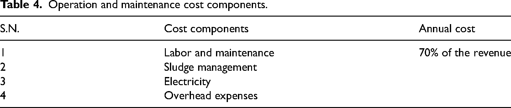

It is assumed that OMC is 70% of the revenue; thus, the OMC value for a revenue of $6220.80 is $4354.56.
Net Present Value
The NPV is a financial metric used to evaluate the investment viability. It calculates the difference between the present values of cash inflows and cash outflows over the effective lifespan of an asset. The NPV can be calculated as follows:
The NPV represents the amount by which the value of an investment exceeds its cost. If the NPV is positive, the investment is expected to provide a greater return than the associated costs, and the project is considered profitable. If the NPV is negative, the investment is considered unprofitable with a low return.
In our case study, the net revenue stream is considered to be consistent throughout the project lifecycle of 10 years. The markup rate is not uniform in different countries; therefore, a standard practice rate of 10% is used to evaluate the NPV by considering a net benefit of $1866.24 after netting off the annual revenue of $6220.80 and OC of $4354.56.
The accounting benefit produces an NPV over an estimated lifespan of 10 years using equation (7), amounting to $11,467.24. After deducting the initial CC of $10,000, the NPV becomes $1467.24; a project with a positive NPV is an acceptable option.
Benefit-to-cost ratio
The BCR is a fast indicator of value addition through a proposal or project. The BCR is computed in monetary terms, where the benefits of projects are compared with CCs. The higher the value of the BCR, the safer the investment; the cost-benefit ratio is the inverse of the BCR.
The operating lifespans, volumes, and efficiencies differ for different components of MFCs, which can be measured using the equivalent cost over the overall life of the MFC on estimated values to present a reasonable result. The BCR is calculated as follows:
The electricity and wastewater treatment revenue are compared with the value of CC, providing a BCR of 1.87; thus, the total revenue is higher than CCs and the investment is viable.
Internal Rate of Return
IRR is an economic evaluation metric that measures investment profitability. It depicts the annualized rate of return for a certain CC, considering the time value of money generated through investment. IRR can be calculated as follows:
At a standard markup rate of 10%, the NPV is positive. The hit and trial method in MS Excel is used to calculate the IRR; the IRR is 13% when NPV = 0. With a markup cost increase of 3%, the NPV becomes 0, and this rate denotes the maximum rate that can be accepted while envisaging the project.
Discounted Payback Period
DPP is a financial metric that measures the time required to recover an investment by considering the time value of money. DPP is computed by dividing the initial investment by the present value of cash inflows. Subsequently, the period required for the current value of cash inflows to equal the initial CC is determined, as follows:
DPP is used to evaluate the feasibility of an investment by comparing the time required to recover the initial investment to a predetermined threshold. An investment is considered a reasonable opportunity if DPP is shorter than the required payback period. If DPP is longer than the required payback period, the investment is deemed unfeasible.
On a discounted revenue stream, the payback period of the considered MFC case is 8.25 years, which is considered unattractive because of the long waiting period to recover the original investment, as can be observed in Table 5.
Payback period with accumulated NPV.
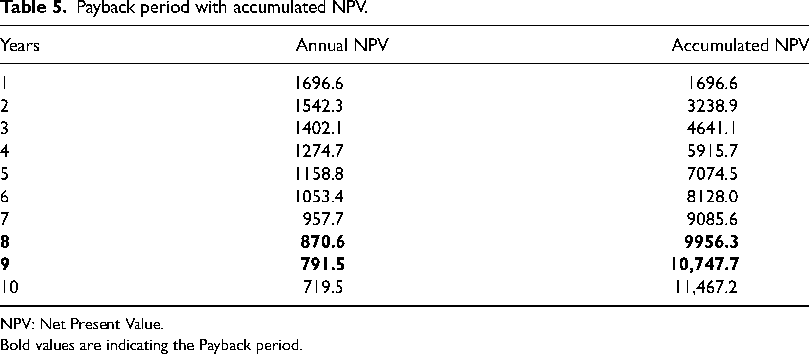
NPV: Net Present Value.
Bold values are indicating the Payback period.
Sensitivity analysis
Sensitivity analysis is a tool or method used to analyze and evaluate the effect of changes in key financial parameters on the anticipated project performance. It is used to analyze risks associated with an investment by assessing the effect of changes in parameters, including cash inflows, discount rates, costs, and other input values. This allows the identification of variables that strongly affect financial outcomes and determine multiple scenarios. This information is essential for making informed decisions and developing contingency plans for managing risks.
Tsekouras et al. (2022) performed a sensitivity analysis by fixing one variable against other variables, where the expected returns were observed and possible combinations were opted for the execution of the project. Moreover, Lotfi et al. (2023) indicated the sensitivity analysis variables for profitability.
In this study, we performed a sensitivity analysis considering three variable factors that directly affected the NPV and project viability. The considered factors were the markup percentage, selling price of electricity and treated water, and OMC. This study presents three scenarios, as listed in Table 6. Table 7 presents the obtained sensitivity analysis results.
Sensitivity analysis scenarios.
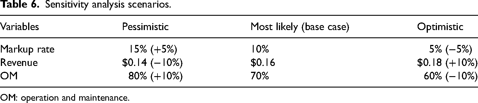
OM: operation and maintenance.
Sensitivity analysis results.
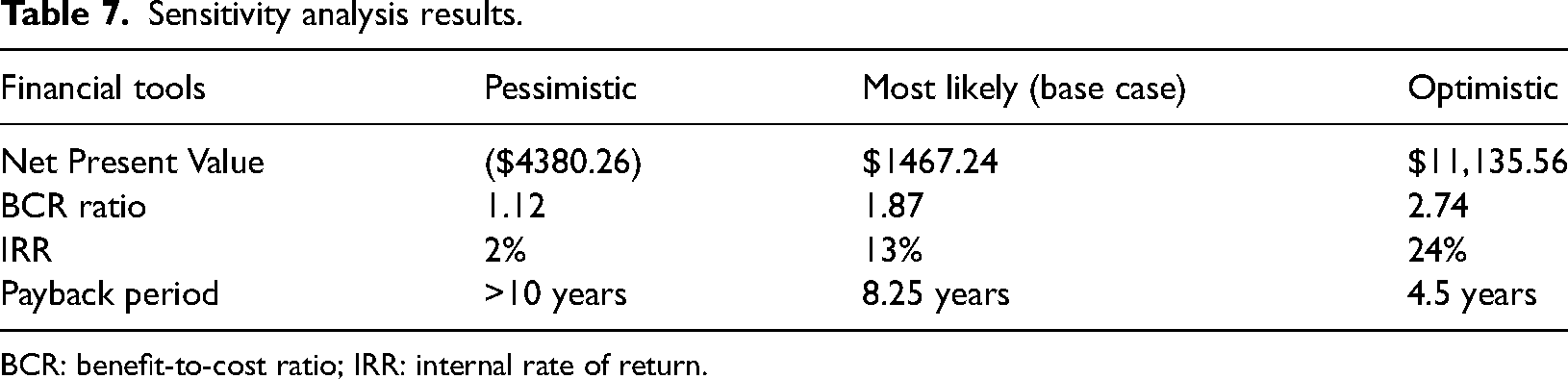
BCR: benefit-to-cost ratio; IRR: internal rate of return.
Figure 15 illustrates the obtained results, which helps make immediate decisions. The first bar shows a negative NPV when the markup rate is higher at 15%, and the revenue decreases by 10%, generating a negative NPV ($4380.26). In the optimistic scenario, the NPV jumps dramatically and provides approximately five times more significant results than the base case. Therefore, some variables can change financial decisions. Figure 16 shows the payback period with respect to CC, where the cutoff point indicates the recovery of the investment at a certain level. Table 8 presents the level of investment recovery for a yearly overview of the payback period, supporting the results presented in Figure 15.
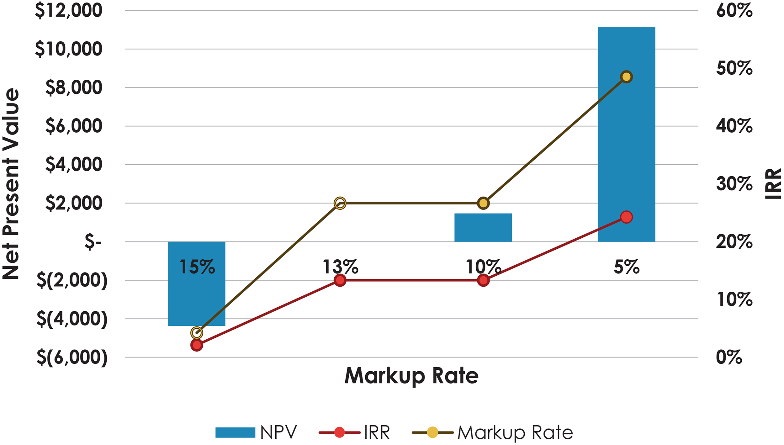
Sensitivity scenarios and IRR level. IRR: internal rate of return; NPV: Net Present Value.
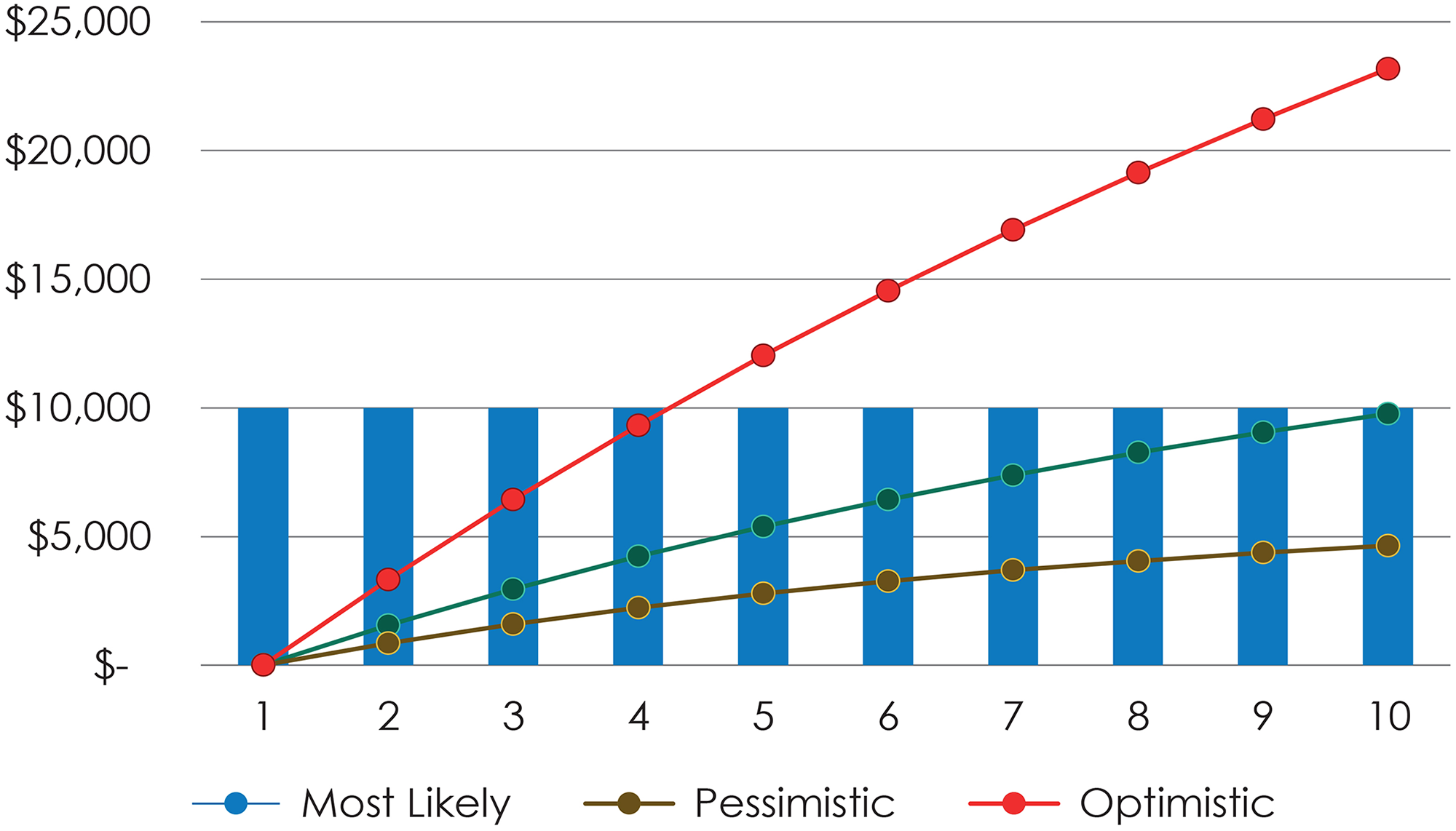
Payback period in different scenarios.
Payback period sensitivity.
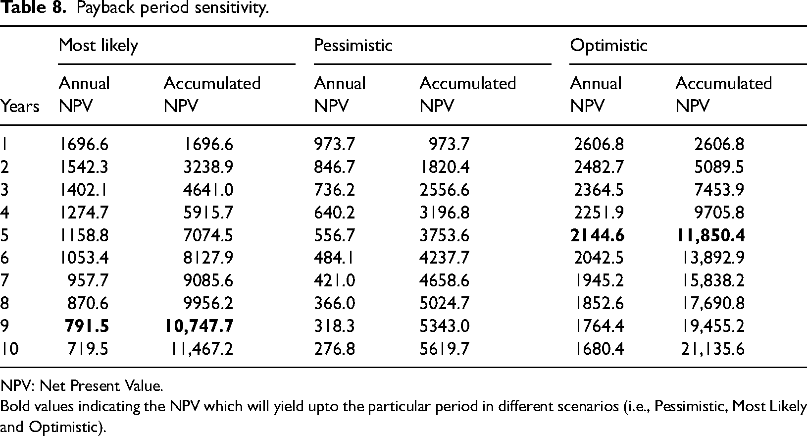
NPV: Net Present Value.
Bold values indicating the NPV which will yield upto the particular period in different scenarios (i.e., Pessimistic, Most Likely and Optimistic).
Goli et al. (2019) elaborated on the sensitivity analysis as two components: risk and return. Risk factors include external factors, such as the economic situation that causes a rise and drop in the demand for electricity and policy decisions for its implementation. However, the return component caters to internal cost reductions to increase profitability.
Scaling-up issues
MFCs are frequently used as off-grid power sources in distant charging systems. Many experimental studies have been conducted on the scaling-up reactors; various combinations of components, such as electrode material and design, membrane design, and stacking techniques with series and parallel connections, were tested for large-scale applications (Tan et al., 2021).
The findings showed that stacked MFCs had more potential for real-world applications because the superlinear power output increased with the addition of stacks in an array as the size of the MFC system increased. To achieve the best outcomes, the MFC size should be maintained small while providing a sufficient fuel supply, that is, wastewater, to achieve an efficient stacking (Kung et al., 2012).
Some of the scaling-up issues in MFCs are as follows:
Mass transfer limitation: The rate of substrate transport to the electrode surface limits the rate of electron transmission between microorganisms and the electrode. At higher scales, mass transfer of the substrate becomes more complex, making access to the electrode surface more difficult for microorganisms. Reactor design: The MFC design is essential for achieving a desirable efficient power generation. The surface-area-to-volume ratio of the MFC can be reduced by scaling up the reactor architecture. pH control: Microorganisms in MFCs are susceptible to pH changes. Controlling the pH within an optimal range for microorganisms becomes more difficult as the volume of the reactor increases. Scaling-up of electrode materials: Electrode materials that satisfactorily work in the laboratory scale may not be appropriate for large-scale MFCs. Producing these materials on a larger scale can also be difficult, and their costs may increase significantly. Costs: Scaling up MFCs can significantly increase the system cost. The associated costs include the cost of materials, production, and maintenance. However, the cost-effectiveness of MFCs at large scales remains a major challenge. Microbial community stability: Microbial communities in MFCs are critical for effective electricity generation. Scaling up MFCs can cause changes in the microbial community, which affects their efficiency.
Addressing these issues requires creative solutions, such as using advanced materials, optimizing reactor design, and creating effective microbial community management strategies.
Discussion
MFCs have a bright future if scientists and engineers find methods to increase their effectiveness and reduce associated costs. One area of focus is the creation of more effective electrode materials and provides designs that can boost power production and lower the associated costs of MFCs. In addition, incorporating MFCs into current wastewater treatment facilities and other sectors of the economy may help lower the total cost and environmental effects. MFCs are expected to gain more attraction as the demand for sustainable energy and wastewater treatment solutions increases.
A number of MFC designs were discussed and analyzed in this study, and the advantages and disadvantages of each design were evaluated to obtain desirable results. PSMFCs can provide greater output on a large scale in terms of electricity generation, while only having the limitation of charge reversal, which can be eliminated with the requisite equipment installation. Other MFC types could be employed based on the implementation level. DCMFCs are considered as an expensive option; however, they can be used for small-scale applications; accordingly, if the cathode and anode become available at low costs, PMFC can be the most feasible option.
The economic review based on the assumptions set demonstrated high CCs and OMCs, where the revenue was comparatively low; thus, MFCs are unfeasible options from an investment perspective. Therefore, the development of low-cost materials must be studied to make MFCs feasible at the commercial level to reap benefits in terms of environmental protection, which directly provides the benefit of carbon eradication and indirectly saves various health and social sector-related costs. In the base-case scenario, the MFC covered the initial CC with a positive NPV of $1467 for the particular lifespan of the MFC installation. The emphasis is on increasing the revenue generation through the enhancement of capacity and reduction of costs, which will improve the present value and ultimately make MFC a feasible energy source.
Conclusions
This study explored two aspects of MFCs. First, the technical parameters and MFC types and structures were reviewed, and the advantages and drawbacks of each structure, including cost-effectiveness, were highlighted. The stacked structures are the most expensive options; however, they provide a higher output than the other types. SMFCs and PMFCs are low-cost options with a stable power output that can be amplified using high-efficiency components, such as anodes, cathodes, and membranes.
Second, CBA was performed as a valuable tool for determining the feasibility of the MFC technology for specific applications. CBA considers the costs of implementing and operating an MFC system, and the potential revenue from electricity generation and waste treatment. The outcome of CBA depends on the specific circumstances of the application, including the availability of organic waste and costs associated with alternative energy sources. As commercial applications are not currently available, optimistic scenarios can provide desirable results. This result can only be maintained through promising revenues to cover costs.
Techno-economic analysis of MFCs suggests that they have the potential to provide sustainable energy and wastewater treatment solutions. The benefits of employing MFCs include the electricity generation, wastewater treatment, environmental protection, and reduced carbon emissions. However, the initial CCs and ongoing OCs of MFCs can be considerable. Despite the challenges and costs associated with the use of MFCs, their potential in helping future energy systems is extremely high. The obtained results provide a basis for analyzing future profitability at certain capacities and developing efficient and long-lasting components.
Consequently, the following conclusions can be drawn:
The size of MFCs can be scaled up using stacked designs for field applications. Investment in MFCs yields unappealing financial results, which can be improved using:
Comprehensive studies on the power generation, wastewater treatment, and carbon emission reduction of MFCs are essential to expand the applications of MFCs in the real-world.
Footnotes
Declaration of conflicting interests
The author(s) declared no potential conflicts of interest with respect to the research, authorship, and/or publication of this article.
Funding
The author(s) disclose the following financial support for the research, authorship, and publication of this article: This research was funded by Africa New Energies Limited, The United Kingdom.