
Abstract
The application of roadway formed automatically by roof cutting (RFARC) technology in the working face under the goaf of close distance coal seam greatly improves the mining rate of resources. However, the existence of overlying remained coal pillar (ORCP) makes the stress environment more complex and greatly increases the difficulty of stability control of RFARC. Hence, the 9101 Working face of Xiashanmao Coal Mine was taking as engineering background. In accordance with the principle of RFARC, the process of crossing the ORCP is introduced, and the calculation formula of the bending deformation of roof is proposed. Through numerical analysis and field test, the stress evolution law of stope and RFARC in the process of crossing ORCP is analyzed. The results show that in the process of crossing the ORCP, the peak stress value of the solid coal side of the RFARC increases continuously, whereas, the stress values of the roof and floor and the gob-side are small. The stress value and caving step distance of roof cutting side of working face are less than those without roof cutting. The stress of stope and RFARC tends to be stable when the working face is lagged 80 m. The combined supporting measures composed of constant resistance and large deformation (CRLD) anchor cable, hydraulic prop and unit support can effectively control the deformation of RFARC. This work provides an effective and economical method to non-pillar mining affected by ORCP in close distance coal seam.
Keywords
Introduction
As an important non-renewable basic energy, coal resource accounts for about 30% of the total energy consumption in the world (Cristobal et al., 2012; Milici et al., 2013). In addition, coal consumption accounted for 56.8% of the total energy consumption in 2020. This indicates that coal resource plays an important role in our economic development. In recent years, with the gradually decreasing of easy coal seam mining, the proportion of close-distance coal seams mining has gradually increased. However, the traditional long-wall mining mode is adopted in most mining areas when exploit in close distance coal seams (As shown in Figure 1(a)) (Qian et al. 2010), and the working face in different coal seams are often arranged in parallel, at an intersection angle or in a cross. Thus, the overlying remained coal pillar (ORCP) results in a great impact on the roadway layout and surrounding rock stability during the lower coal seam mining. And many studies on the reasonable layout of roadways have been carried out to determine the location of roadways under the influence of ORCP (Liu et al., 2016; Wu et al., 2018; Yan et al., 2015). Besides, in order to determinate the control measures of surrounding rock stability, it is necessary to study the stress distribution characteristics of ORCP and the optimal coal pillar size (Gao et al., 2019; Sun et al., 2020a). However, the traditional long-wall mining mode not only cannot completely relief the relationship between the excavation and mining fundamentally, but also cannot increase the mining rate in the mining process of close distance coal seams.
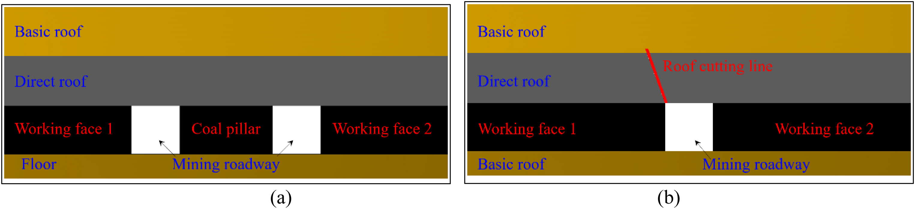
Comparison of traditional longwall mining and no-pillar mining. (a) traditional longwall mining (b) no-pillar mining(RFARC).
For purpose of completely removing the coal pillars, and optimizing the gob-side entry retaining technology, the roadway formed automatically by roof cutting (RFARC), which was based on the theory of “cutting cantilever beam” was proposed (He et al., 2015). This technology reinforces roof support strength by Constant resistance and large deformation (CRLD) anchor cables and cuts off the roof connection between roadway and working face through the bilateral cumulative tensile explosion (BCTE) technology (He et al., 2015), which aims to cut off the stress transfer path. After the working face is mined, the stope roof breaks, expands, and automatically collapses under the mine pressure to form a new gangue side of roadway (As shown in Figure 1(b)). In the exploitation process, only one roadway will be excavated for one working face, which greatly alleviates the problem of mining alternating tension (He et al., 2015; Peng et al., 2019; Wang et al., 2018; Zhang et al., 2011, 2020a). Yang et al. (2019) pointed out the key technology and design method of RFARC. In the field test, the reasonable roof cutting parameters should be determined firstly. The roof cutting height should meet the supporting effect of caving gangue on the basic roof. The roof cutting angle should meet the mechanical conditions of collapse along the pre-splitting surface and deflect to the goaf side to achieve the smooth caving of gangue (Hu et al., 2019; Sun et al., 2014). Many scholars have studied the application of roof cutting technology in different buried depths. Tian et al. (2022) studied the stability control measures at a shallow mining depth, a single-hydraulic prop, I-beam and steel mesh were proposed. Guo et al. (2019) analyzed the application effect of RFARC in large buried depth, and determined the surrounding rock stability control measures with “CRLD anchor cables and support for side protection”. Sun et al. (2020b) conducted a physical model test to study the overlying strata movement law. Zhang et al. (2020b) studied the stress evolution law in the process of secondary reuse of three soft coal seams by numerical simulation. He et al. (2018) compared and analyzed the stress distribution characteristics of stope under different mining modes. Ma et al. (2018) studied the roof caving law of RFARC in medium thick coal seam by field monitoring.
Previous studies of RFARC were based on single layer coal seam, However, when the RFARC is applied in close distance coal seams, compared with the single coal seam, the mining influence between upper and lower coal seams will gradually increase with the decrease of coal seam spacing, meanwhile, the mining superposition stress field generated in the mining process of the working face is very complex. When the upper coal seam is mined, the damaged floor is used as the roof of the lower coal seam. This reduces the integrity and bearing capacity of the rock layer, and increases the difficulty of stability control of the lower coal seam mining roadway. Especially when the working faces of lower coal seam are arranged at an intersection angle or in a cross, the existence of the ORCP will further increase the stability control difficulty of RFARC. Therefore, in this paper, Xiashanmao coal mine, where the working faces of upper and lower coal seams were arranged in a cross, was taken as the engineering background. During crossing the ORCP, the mine pressure distribution characteristics in the stope, the stress evolution law and stability control measures of RFARC were studied.
Technique and mechanism
Process of RFARC
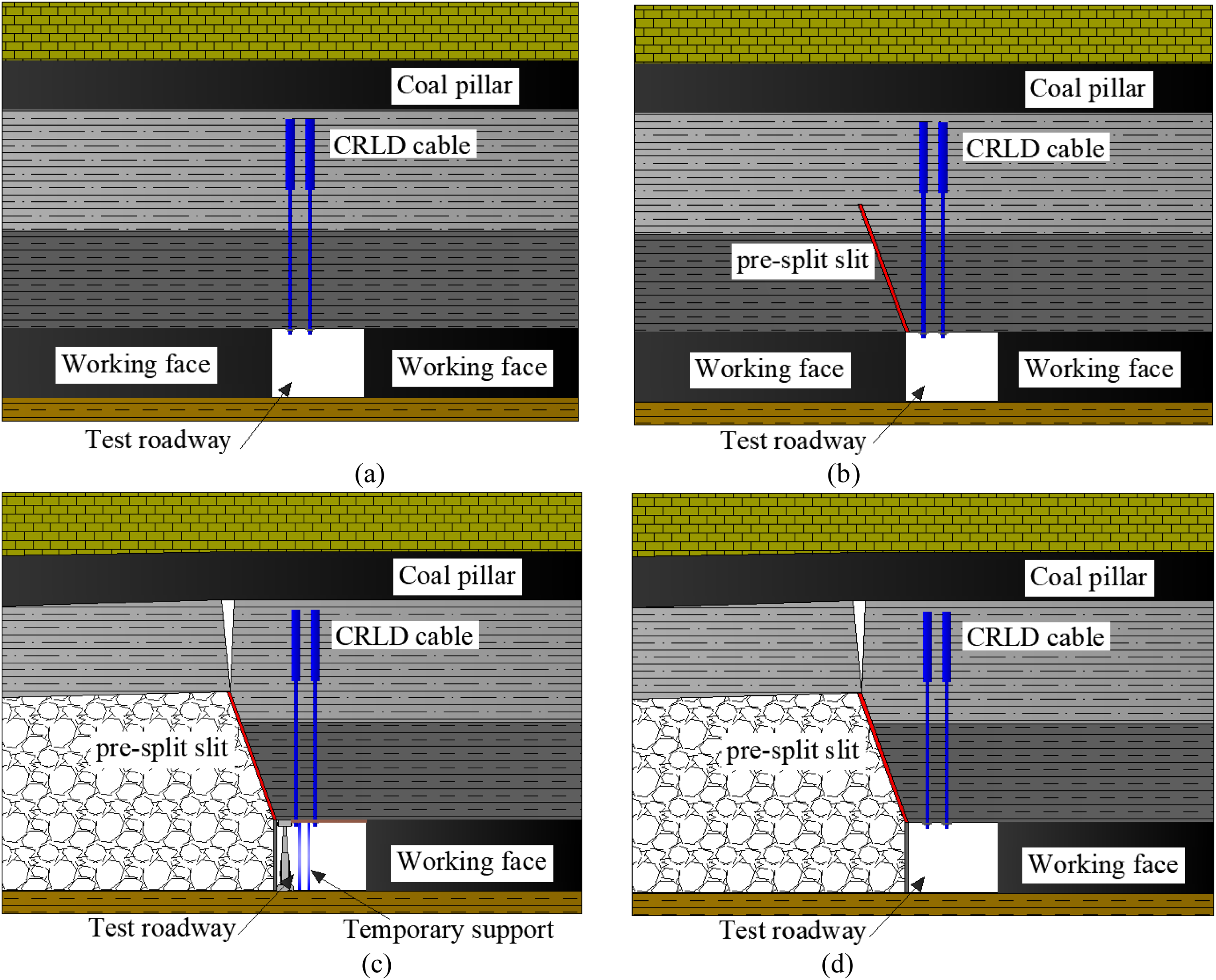
The technology of RFARC cuts off the roof connection between stope and roadway. After the working face is mined, the roadway roof forms a “short-wall beam” structure and the stope roof collapses along the roof cutting seam automatically under the action of mine pressure, meanwhile, a new roadway gangue side will form. When there is an ORCP, the process of RFARC can be divided into four stages, which is shown in Figure 2.
Schematic diagram of crossing ORCP in RFARC. (a) First stage. (b) Second stage. (c) Third stage. (d) Fourth stage.
The first stage is reinforcement support stage. Before crossing the ORCP, the surrounding rock of roadway should be reinforced, so as to enhance the integrity and bending stiffness of the roof strata. According to previous research, the CRLD anchor cable support technology is used (He et al., 2014), which is shown in Figure 2(a).
The second stage is pre-splitting roof stage. Before crossing the ORCP, the roof cutting technology is introduced to form roof pre-slit seam. This can change the roadway roof structure along the goaf side from the fixed end to the simple end. It can accelerate the roof strata caving and reduce the roadway roof bending subsidence caused by overlying strata movement, which is shown in Figure 2(b).
The third stage is temporary support stage. Before crossing the ORCP, in the influence area of the advanced mining stress and the stress concentration caused by ORCP, the temporary support in roadway is introduced. After crossing the ORCP, in order to reduce the influence of rock strata movement on the stability of RFARC, the temporary support should be further strengthened. At the same time, the gangue is prevented from pouring into the roadway through the roadside gangue support technology, which is shown in Figure 2(c).
The fourth stage is roadway stability stage. After crossing the ORCP, when gangue is compacted and the movement of roof strata is stable, the temporary supports in the roadway will be withdrawn to realize the roadway formed automatically, which is shown in Figure 2(d).
Mechanism of ORCP and RFARC
After crossing the ORCP, the roof structure of RFARC can be simplified as cantilever beam (as shown in Figure 3).
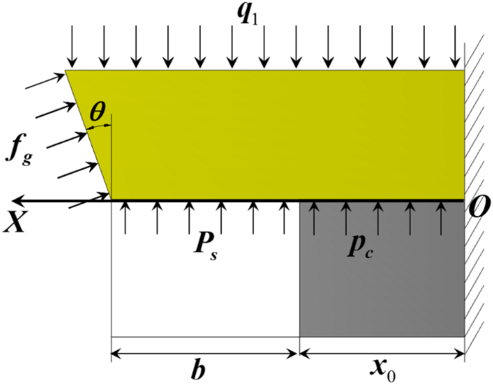
Mechanical model diagram.
According to Figure 3, the load acting on the direct roof is:

The deflection deformation of roadway roof is an important standard to measure the effect of RFARC, when calculating roadway deformation, the force condition is simplified as four parts. As shown in Figure 4
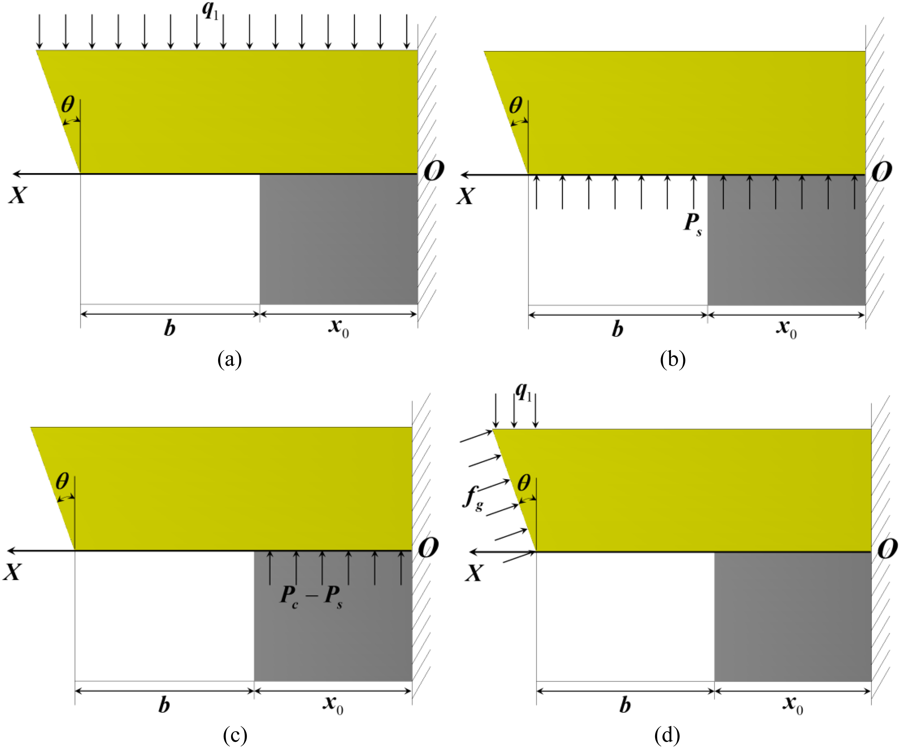
Simplified schematic diagram of roadway roof deflection calculation.
The superposition method is used to calculate the flexural deformation of roadway roof (Sun et al. 2009). When only

When only

When only
When only

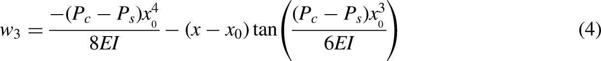
Joint equations (2)–(5):


According to equation (9), the roof deformation is related to the upper load of direct roof, rock lithologic, strength of artificial support, supporting force of gangue and bearing strength of coal body. the bending deformation of direct roof will increase with the enhancement of upper load and roadway width; it will decrease with the increase of roadway support strength and coal support capacity. Meanwhile, if the stope gangue collapses faster, it can effectively support the roof and reduce the roof deformation to a certain extent.
In the close-distance coal seams, when the working face is arranged in a cross, after the upper coal seam is mined, the position relationship between the ORCP and the mining roadway of lower coal seam is shown in Figure 5.
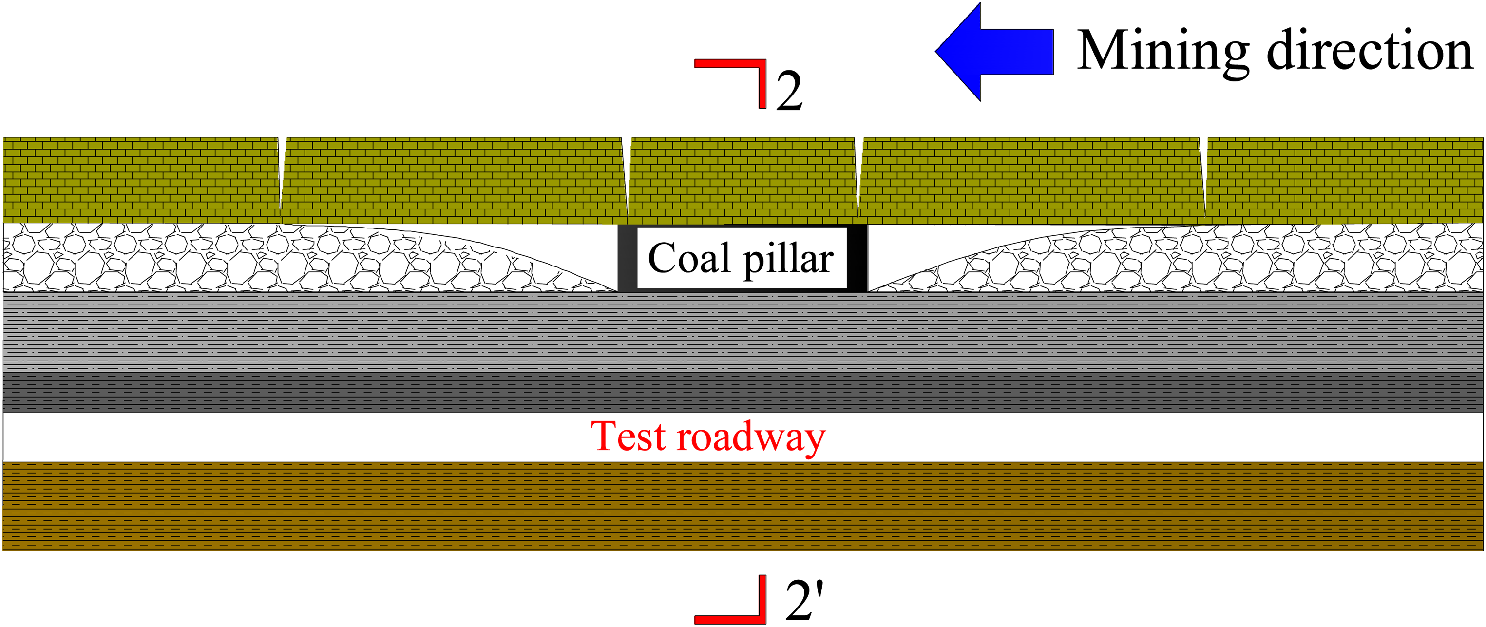
Position relationship between test roadway and ORCP.
The existence of ORCP will lead to the insufficient collapse of the roof, and transfer high stress downward. The vertical stress transfer calculation formula of the ORCP is as follow (Gao et al., 2019; Wu et al., 2018; Zhang et al., 2018):

According to equation (10), the stress value at any position (x, y) in the floor rock is related to the horizontal and vertical distance away from the center of ORCP. There will be an obvious stress concentration area in the floor strata. This will increase the load on cantilever beam and increase the deformation of surrounding rock. Therefore, it is necessary to analyze the stress evolution law of stope and RFARC, and increase the support strength to decrease the roof deformation.
Stress characteristics of RFARC crossing ORCP
Numerical model construction
In order to study the mine pressure distribution law of working face and RFARC during crossing the ORCP, a three-dimensional finite difference model was constructed by FLAC3D. The size of numerical model was 240 m × 300 m × 100 m (length × width × height). And there are 11 rock layers from top to bottom, which is shown in Figures 6.
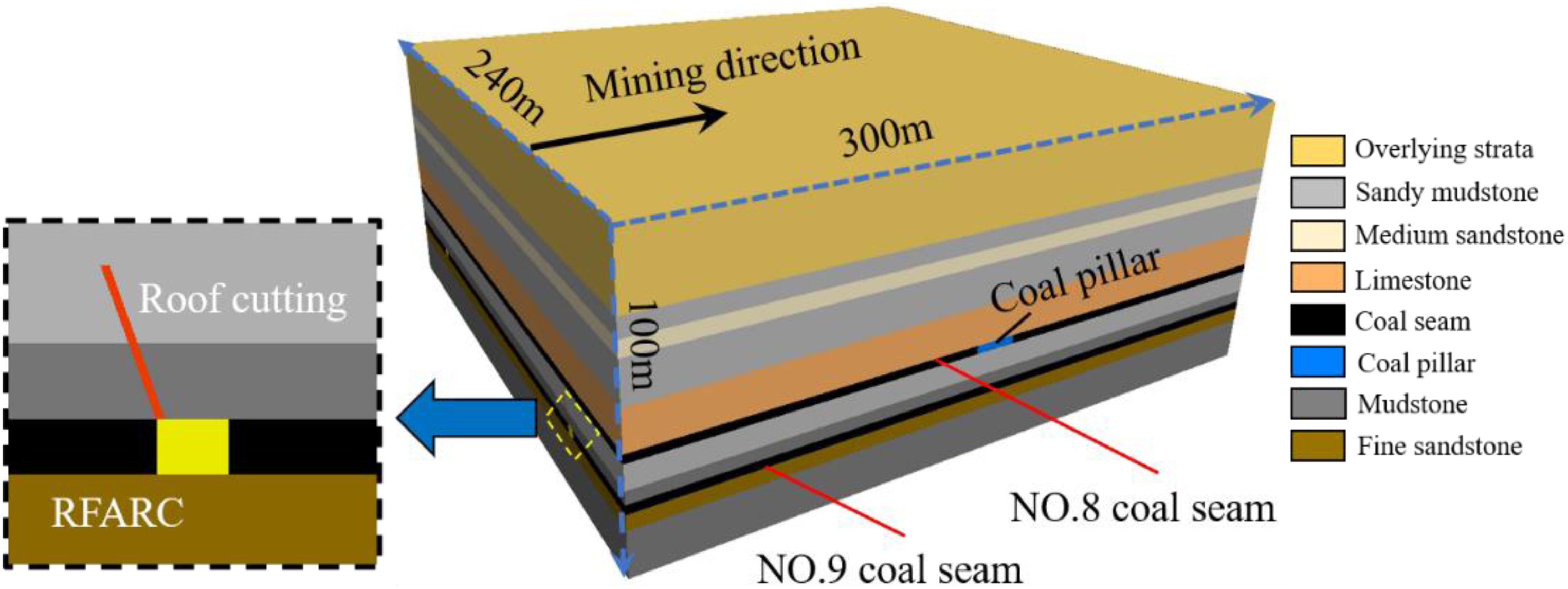
Three-dimensional numerical calculation model.
The model was established based on Xiashanmao Coal Mine, as shown in Field test. In the model, the bottom was fixed, the horizontal movement was limited, and the top surface was the stress boundary. Meanwhile, 3.3 MPa was applied to simulate the overlying rock strata weight. According to the field measurement, the horizontal stress coefficient was 1.0. In the simulation process, the roof cutting height was 8.5 m and the roof cutting angle was 20 degrees. The mechanical tests were carried out on different rock strata to determine the basic rock mechanical parameters. The Mohr-Coulomb constitutive model was selected and the mechanical parameters were shown in Table 1.
The main mechanical parameters of physical model strata

According to the actual mining sequence, the upper coal seams was mined firstly with the mining distance of 10.0 m each step. The ORCP was located in the area of 140–155 m with a width of 15.0 m. After the overlying working faces were mined out and the roof strata collapse was stable, the mining roadway was excavated secondly. Then, the mining of 9101 working face was carried out with 10.0 m each step. The mining direction was perpendicular to the mining direction of upper coal seam.
Effect on stress evolution of stope
In the process of 9101 working face crossing the ORCP, the vertical stress of stope was extracted. Before crossing the ORCP, the vertical stress was shown in Figure 7.
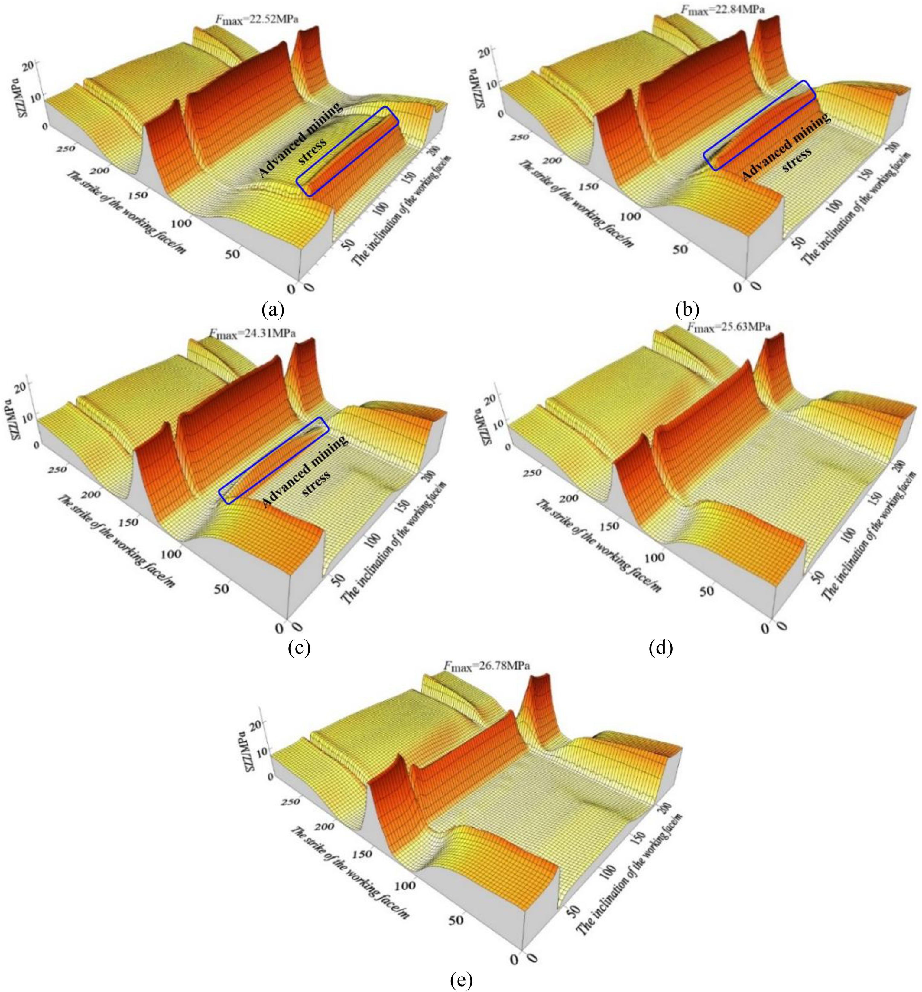
Stress distribution of stope before crossing the ORCP. (a) 120 m away from the ORCP (b) 80 m away from the ORCP (c) 40 m away from the ORCP (d) 20 m away from the ORCP (e) 0 m away from the ORCP.
It could be seen that there was a certain high stress concentration area before crossing the ORCP. When the working face was 120 m away from the ORCP, the peak value of the concentrated stress zone of stope was located below the ORCP, which was 22.52 MPa and the stress concentration coefficient was 4.50. Besides, there was evident advanced mining stress (as shown in Figure 7(a)). When the working face was 80 m away (Figure 7(b)), the peak stress value in the stope increased slightly with the value of 22.84 MPa. When the distance was 40 m (Figure 7(c)), the stress distribution began to be affected by the concentrated stress of the ORCP, the peak value of stress concentration increased gradually which reached 24.31 MPa. This was caused by the superposition of the advanced mining stress and the concentrated stress of the ORCP, however, the advanced mining stress decreased. When the distance was 20 m (Figure 7(d)), the stress concentration zone began to transfer to boths solid coal sides, the advanced mining stress of the working face decreased, and the peak stress in the stope continued to increase with the peak value 25.63 MPa, which appeared on the solid coal side of roadway. When mined to the ORCP (Figure 7(e)), the advanced mining stress of the stope reached the maximum with the peak value 26.78 MPa. The peak value appeared in the solid coal side on both sides of the roadway.
After crossing the ORCP, the stress distribution of stope was shown in Figure 8. When the ORCP was lagged behind the working face 0 m (Figure 8(a)), the peak stress concentration in the stope was 26.80 MPa, which appeared on the solid coal side of the roadway without roof cutting. With the increase of the distance between the ORCP and the working face, the stress concentration in the solid coal side increased continuously, and the advanced mining stress increased gradually. When lagged behind the working face 60 m (Figure 8(c)), the stress of the stope gradually tended to be stable. It meaned the movement of the roof strata under the ORCP gradually decreased, and the peak stress in the stope was 27.32 MPa. When lagged behind the working face 100 m (Figure 8(d)), the peak stress in the mining field was 27.91 MPa, with a relatively small increase.
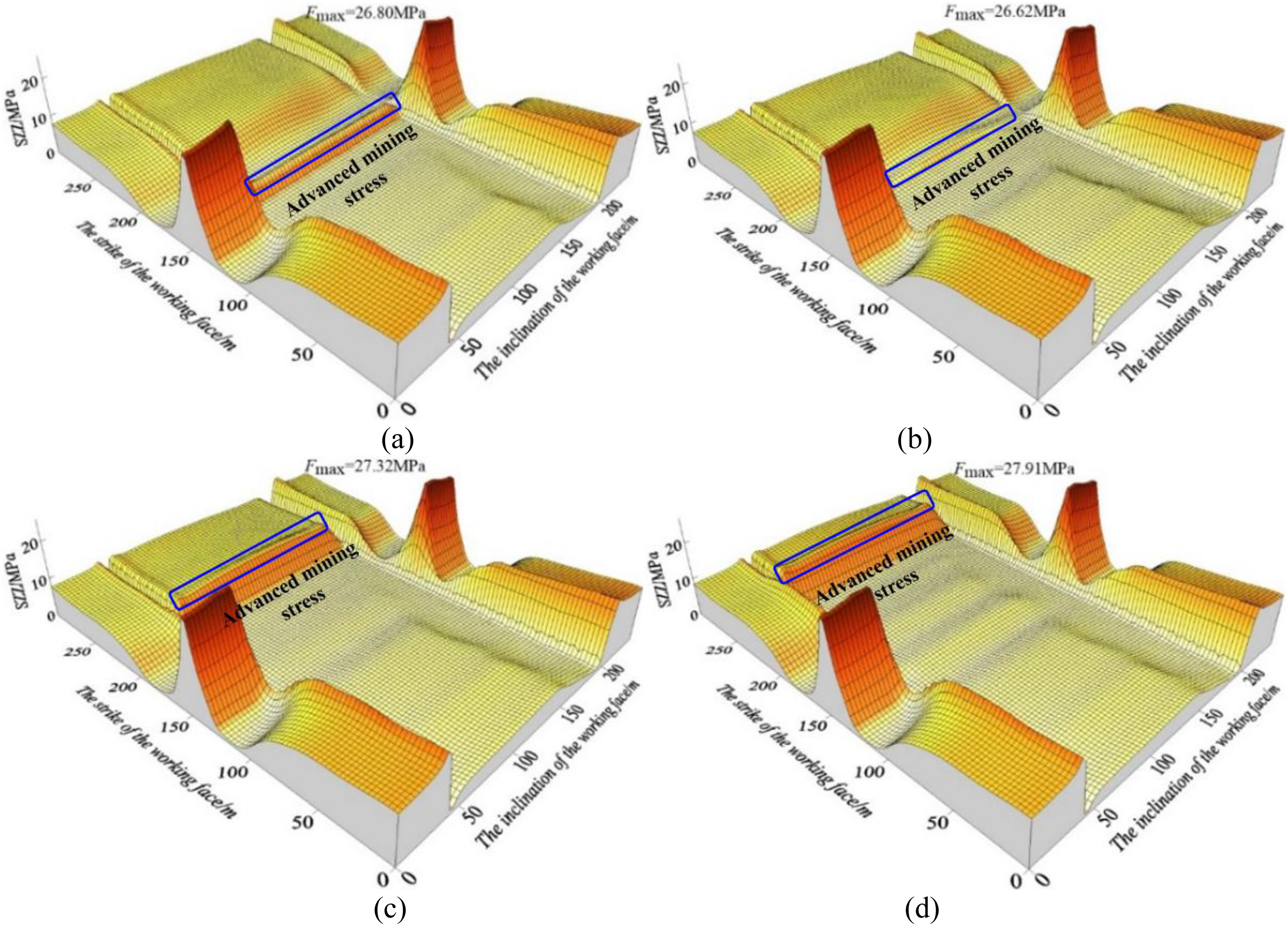
Stress distribution of stope after crossing the ORCP. (a) Lagged behind the working face 0 m (b) Lagged behind the working face 25 m (c) Lagged behind the working face 60 m (d) Lagged behind the working face 100 m.
According to the stress distribution curve, before crossing the ORCP (Figure 9(a)), when the working face was far away from the ORCP (more than 40 m), the roof cutting had little effect on the stress distribution, and the stress value of the working face was basically the same as that in two side of roadway. With the decrease of the distance between working face and ORCP, the stress value of working face gradually decreased, oppositely, the stress value in both coal side of roadway was gradually increased. The reason was the ruduction of coal load-bearing capacity made stress transfer to solid coal side of roadway. Affected by advanced roof cutting, the stress value of working face closed to return air roadway was smaller than that closed to haulage roadway.
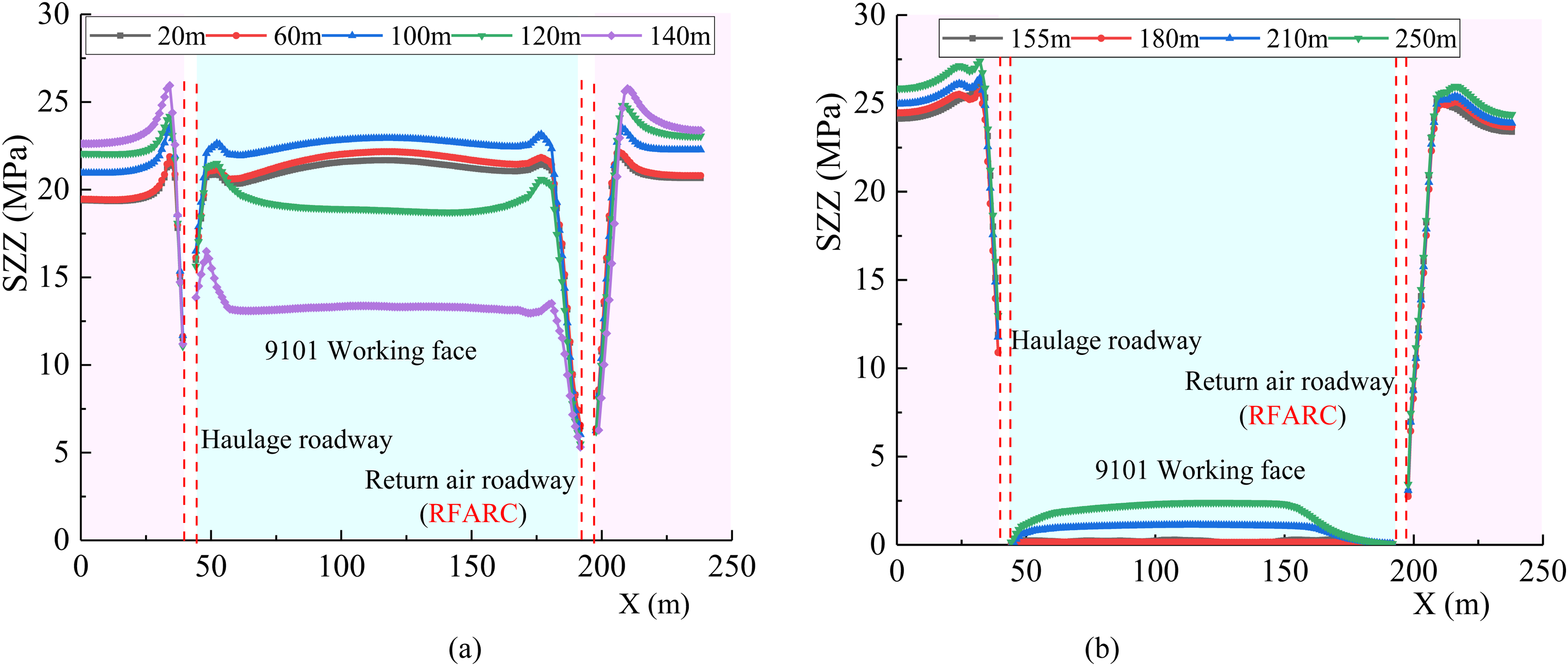
Vertical stress curve inclination of working face at Y direction 150 m. (a) Before crossing the ORCP. (b) After crossing the ORCP.
After crossing the ORCP(as shown in Figure 9(b)), when the working face mined through ORCP, the original equilibrium state of rock stratum was broken, the stress under the ORCP in working face was released, and the stress in solid coal side was more concentrated. With the distance of lagging working face increasing, a certain degree of stress recovery occurred in the stope. In the whole mining process, the stress in working face near the roof cutting side was lower than that near the non-roof cutting side. The stress concentration degree in solid coal side of RFARC was less than that in solid coal side of non-roof cutting roadway. This was mainly due to the application of roof cutting technology cut off the stress transmission path between the roof of stope and roadway, and reduced the stress transmit to the next working face.
Effect on stress evolution of RFARC
When the RFARC need to cross the high stress area formed by the ORCP, which increased the difficulty for the stability control of surrounding rock of RFARC. In order to study the stress evolution law of RFARC during crossing the ORCP, the section which was located at Y direction 150 m of RFARC was taken as the monitoring plane. The stress distribution contour of surrounding rock of RFARC is shown in Figure 10.
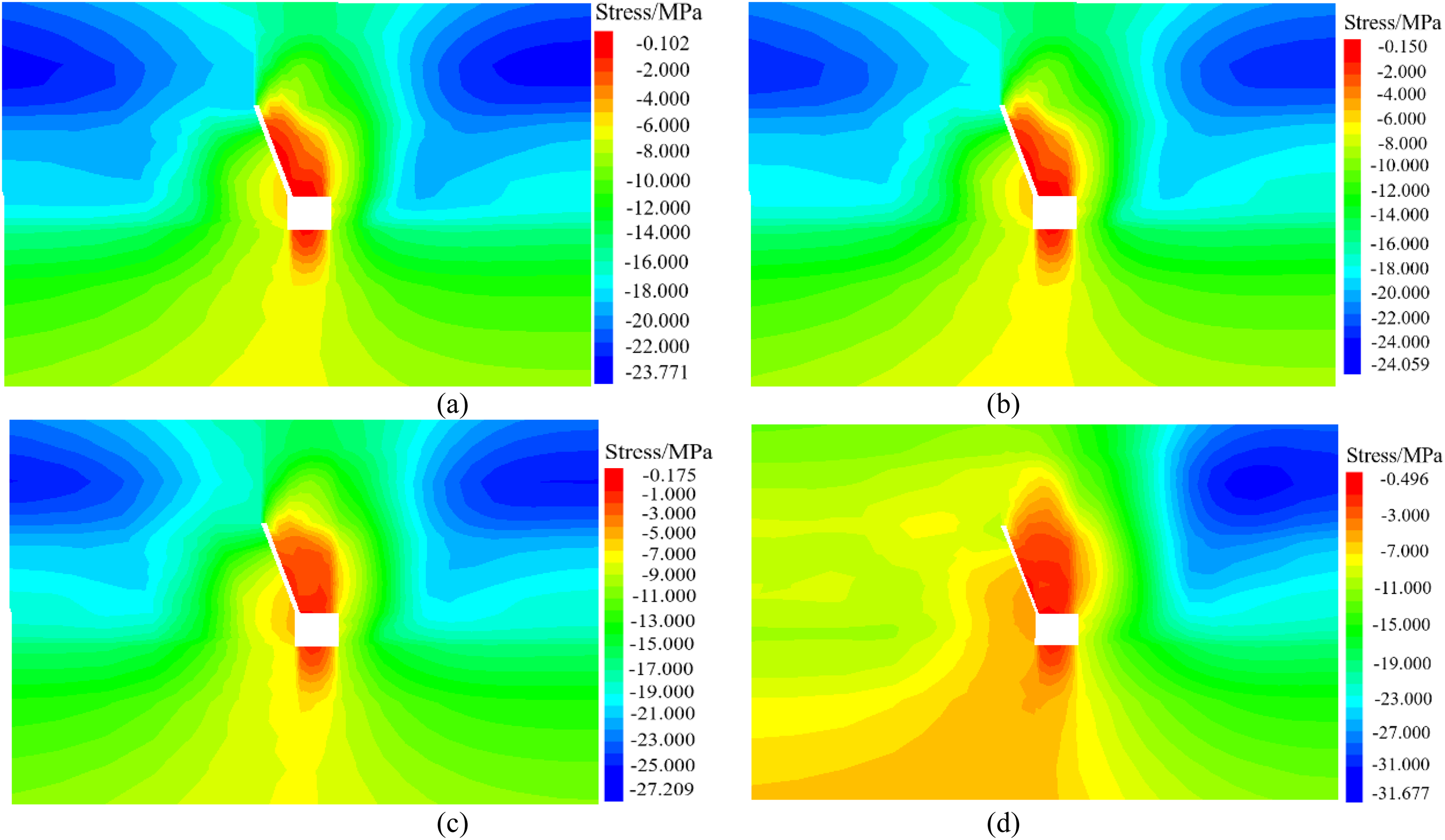
Stress evolution law of surrounding rock of RFARC after crossing the ORCP. (a) 120 m away from ORCP. (b) 80 m away from ORCP. (c) 40 m away from ORCP. (d) 0 m away from ORCP.
Before crossing the ORCP, both sides of roadway were in high stress concentration area, and the roof and floor strata of roadway were in low stress area. The height of the low stress area of roof was greater than or equal to the roof cutting height. When the distance between the working face and the monitor plane was greater than 80 m (Figure 10(a) and (b)), the stress distribution of the surrounding rock of the roadway was basically not affected by the mining. The stress concentration degree in solid coal side (right side) and the roof cutting side (left side) was basically the same with the value 24.06 MPa. When the working face was less than 80 m and greater than 40 m away from the monitor plane, the stress concentration degree increased gradually. When the working face was 40 m (Figure 10(c)) away, the peak stress value was 27.209 MPa. When the distance was less than 40 m away, with the distance to monitor plane decreasing, the stress concentration degree of right side continued to increase, and the stress concentration of left side continued to decrease. This was caused by the superposition of advanced mining stress and concentrated stress formed by ORCP. When mined to the monitor plane (Figure 10(d)), the stress concentration value of right side was 31.68 MPa.
When the working face mined through the monitor plane, the stress concentration in solid coal side increased gradually, and the peak stress value was 32.098 MPa. The low stress area of roof and floor was enlarged (Figure 11(a)). With the increase of distance, the stress concentration degree in solid coal side was augmented. When lagged working face 60 m (Figure 11(c), the peak stress concentration of right side was 34.422 MPa. When lagged working face 80 m (Figure 11(d)), the stress concentration of solid coal side increased slightly, with the peak stress value 35.245 MPa.
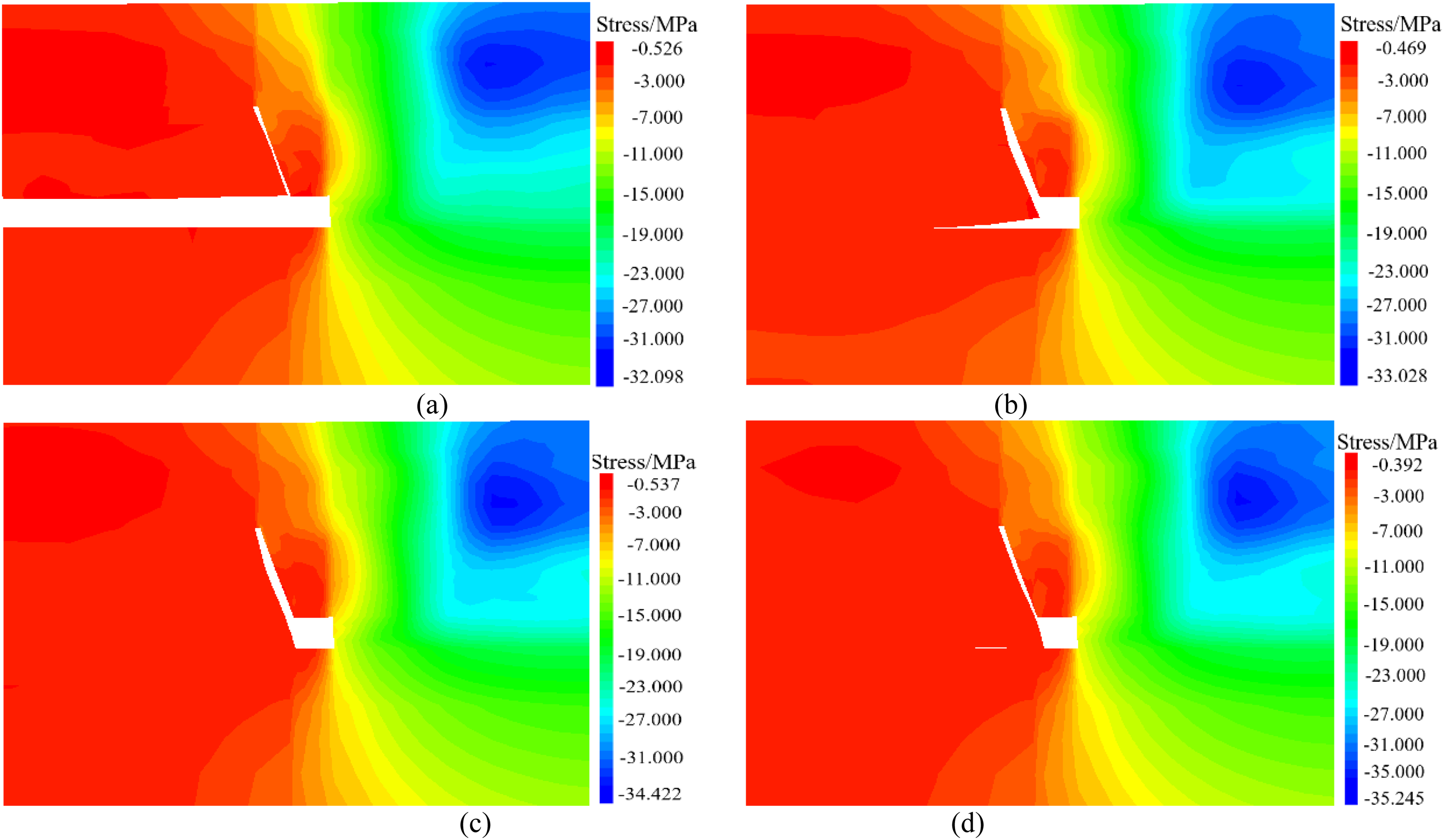
Stress evolution law of surrounding rock of RFARC after crossing the ORCP. (a) Lag working face 5 m. (b) Lag working face 10 m. (c) Lag working face 60 m. (d) Lag working face 80 m.
Compressive showed that the roof cutting had little effect on the stress distribution characteristics of the stope before crossing the ORCP. With the decreasing of distance to the ORCP, the superposition of the advanced mining stress and the ORCP residual stress in the working face increased. When the stress exceeded the compressive strength of the coal body, the stress transferred to both sides, resulting in the stress reduction in working face and stress strengthening in solid coal side of roadway. After crossing the residual coal pillar, the stress distribution characteristics was affected obviously. The stress on both sides of the RFARC was significantly lower than that without roof cutting. When the lag distance reached 60 m, the stress on both sides of the stope and the RFARC gradually tends to be stable.
Field test
Engineering overview
Xiashanmao Coal Mine, which is located in Liulin Mining Area, Lvliang City, Shanxi Province (Figure 12(a)), was selected as the engineering background. It is a typical close-distance coal seams mine and its annual approved production capacity is 1.2 × 10⁹ kg. The mining coal seam is NO.9, which is located in the lower part of Taiyuan Formation in Shanxi. And the distance between the NO.9 coal seam and the overlying NO.8 coal seam is 11.20–16.42 m. The average coal seam distance is 12.2 m. The average buried depth of coal seam is 200 m.
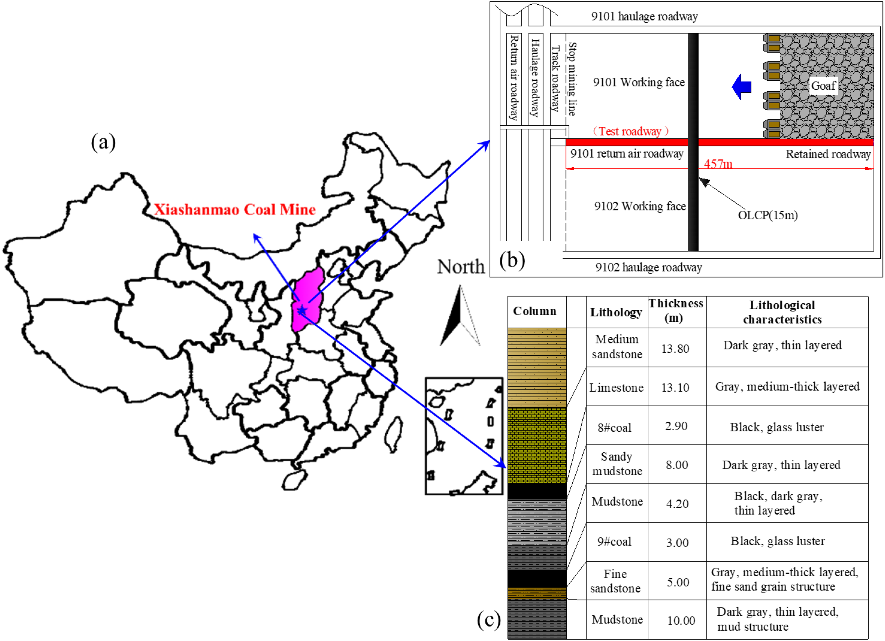
Geological background of test site. (a) Location of Xiashanmao Coal Mine. (b) Layout of working face. (c) Lithological column.
The 9101 working face was taking as the experimental field, which employed mechanized mining technology to mine the full height simultaneously. The inclined and strike length of the working face were 150 m and 480 m respectively. The average thickness of coal seam is 3.0 m with a dip angle of 2–4°. The overlying NO.8 coal seam adopted the traditional long-wall mining mode with the coal pillar 15.0 m. And the mining direction of NO.8 coal seam and 9101 working face was in a cross arrangement. Therefore, the 9101 working face and the RFARC need to cross the ORCP during mining process (Figure 12(b)). This effected the distribution characteristics of mine pressure and the stability control of roadway surrounding rock. The height and width of the test roadway, which was the return air roadway of 9101 working face, were 3.0 m and 4.0 m respectively. The lithology of the roof and floor is shown in Figure 12(c).
Support design
According to the numerical analysis, in order to decrease the deformation of surrounding rock, meanwhile, ensure crossing the ORCP safely and efficiently, the roadway was reinforced on the basis of the original support. Firstly, three rows of CRLD anchor cables were carried out to reinforce the roof. The diameter of the CRLD was 21.8 mm, the length was 10,300 mm, the constant resistance value was 32 ± 3 t, and the pre-tightening force was not less than 25 t. The first row was connected with W steel strip. The second row was connected with steel ladder beam. The third row tilted 15° towards the solid coal side and was connected with steel ladder beam. Secondly, two rows of ordinary anchor cables were carried out to reinforce the solid coal side. Each row of anchor cables was connected with W steel strip. The sectional view and plan view of reinforcement support are shown in Figure 13.
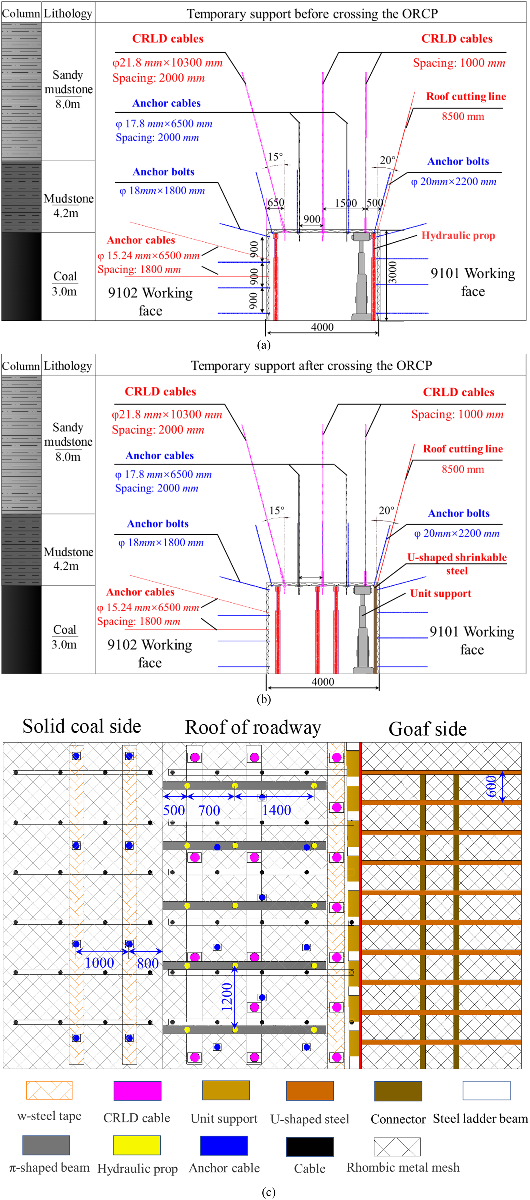
Support design diagram (a) sectional view of strengthened support (b) sectional view of temporary support after crossing the ORCP (c) plan view of temporary support after crossing ORCP.
In the process of conventional RFARC, the roadway can be divided into three zones according to the influence of mining stress: the advanced mining stress influence zone, the dynamic pressure influence zone and the stability zone. Before crossing the ORCP, with the decrease of the distance between working face and ORCP, the advanced mining stress and the high stress concentration under the influence of ORCP were superimposed, which can easily lead to the deformation or instability of the surrounding rock. The temporary support was set in roadway 20 m ahead. It was consisted of “One π-shaped beam, two hydraulic prop and one unit support”, as is shown in Figure 13(a). After crossing the ORCP, the stability of RFARC was affected by the dynamic pressure and the high stress concentration caused by the ORCP, the temporary support strengthened with “One π-shaped beam, three hydraulic prop and one unit support”. The goaf side of RFARC was supported by U-shaped shrinkable steel with connector, and the distance between the U-shaped steel was 600 mm, as shown in Figure 13(b) and (c).
To understand the mine pressure of working face and the effect of surrounding rock control measures during crossing the ORCP, the stress sensors were installed on the working face and the displacement measuring stations were set in the test roadway. The detailed layout of stress sensors and displacement stations are shown in Figure 14. Three displacement measuring stations were arranged, one was set under the ORCP, the other two were respectively arranged before and after crossing the ORCP, 20 m away from the center of ORCP.
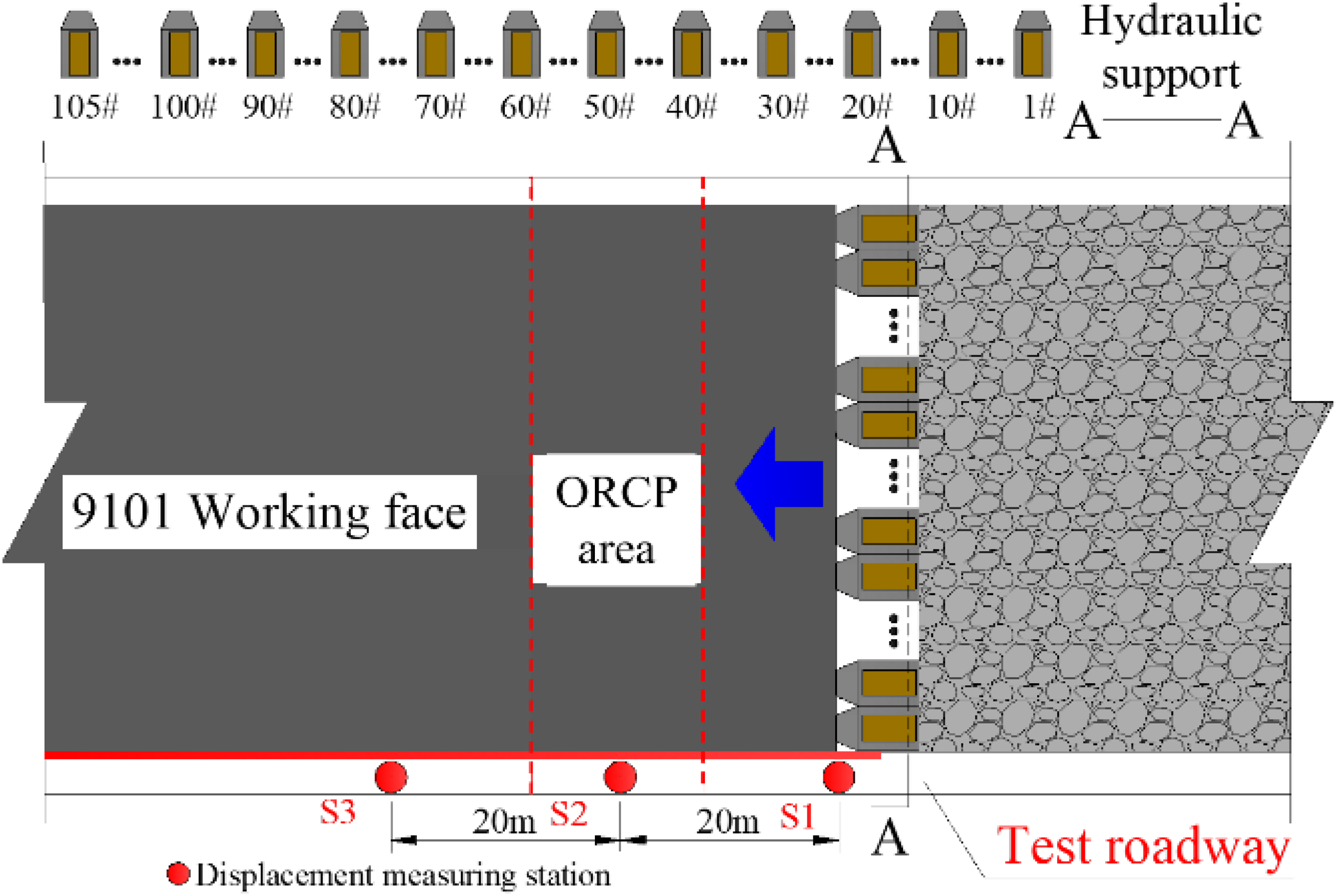
Layout of displacement measuring stations and hydraulic supports with stress sensors.
Twelve hydraulic supports were equipped with stress monitor sensors. They were respectively installed in 4#, 15#,26#,37#, 48#, 59#, 70#, 81#, 87#, 94#, 98# and 104# supports, which was used to monitor the pressure change, so as to understand the strata movement during crossing the ORCP. In order to study the mine pressure difference of working face closing to non-roof cutting side and roof cutting side, the stress sensors of 4# and 104# hydraulic supports was selected. They are respectively located in the influence area of the working face with no roof cutting and in the influence area with roof cutting.
Analysis and effect of the RFARC
The pressure data of hydraulic supports with sensors in the working face and the roadway deformation could be used directly to study the mine pressure and the effect of RFARC in the process of crossing the ORCP. The ORCP is located at 150 m along the strike of working face, therefore, the pressure data of 40 m before and after crossing the ORCP are selected for analysis. The pressure changes of hydraulic supports during crossing the ORCP was shown in Figure 15.
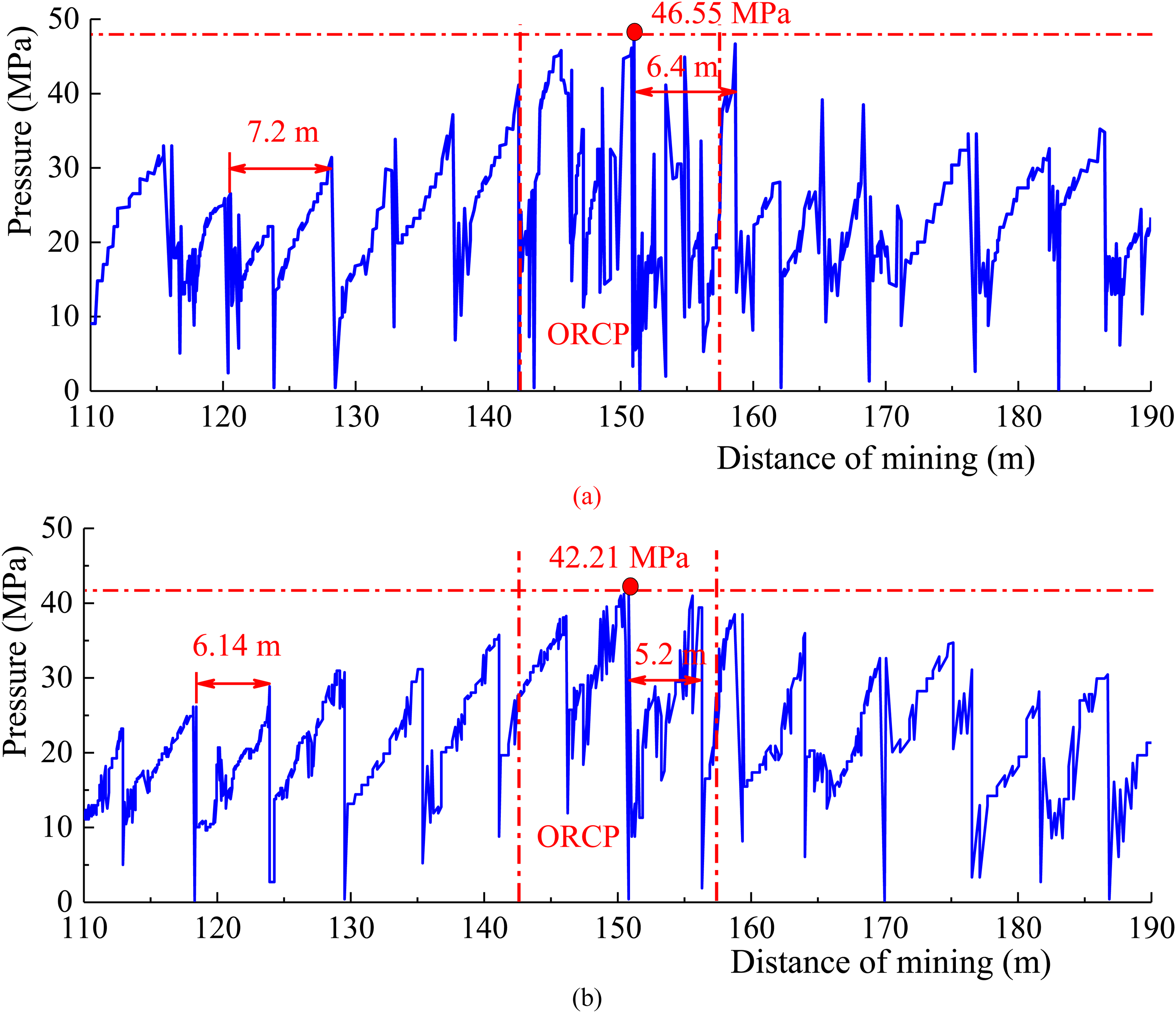
Stress curves of the working face crossing ORCP (a) 4# hydraulic support (no roof cutting side) (b) 104# hydraulic support (roof cutting side).
It can be divided into three zones: the area before crossing the ORCP, the area under the ORCP and the area after crossing the ORCP. Before crossing the ORCP, the distance between the working face and ORCP was decreased with mining, the peak pressure of hydraulic support increases gradually. When mined under the ORCP, the pressure of hydraulic support reached the maximum value. After crossing the ORCP, the peak pressure of hydraulic support decreased gradually. In the no roof cutting side (Figure 15(a)), the roof caving step was about 7.2 m before and after passing through the ORCP. In the affected area of the ORCP, the roof caving step was 6.4 m, and the peak pressure of the hydraulic support was 46.55 MPa. In the roof cutting side (Figure 15(b)), the roof caving step was about 6.14 m before and after passing through the ORCP. In the area under the ORCP, the roof caving step was 5.2 m, and the peak pressure of the hydraulic support was 42.21 MPa. No matter on the roof cutting side or the no roof cutting side, the roof caving step was small, which is because the mining of overlying coal seam broke the integrity of the roof.
The deformation of roadway surrounding rock can effectively evaluate the support effect of RFARC during crossing the ORCP. The surrounding rock deformation curve of different stations lag working face in RFARC was shown in Figure 16.
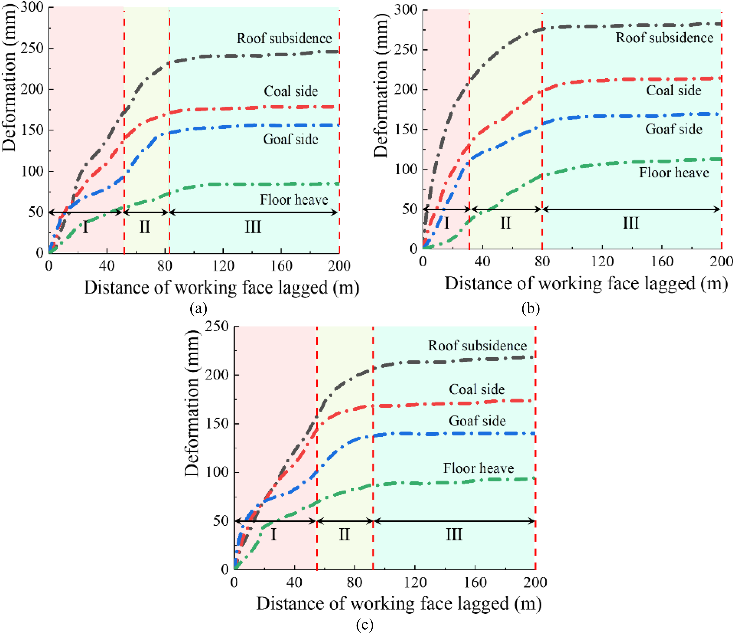
Deformation curves of measurement station in the RFARC. (a) Station S1. (b) Station S2. (c) Station S3.
The curves can be divided into three zones: rapid deformation zone (I), deceleration deformation zone (II) and stable deformation zone (III). Firstly, Figure 16(a) showed that the deformation curve before crossing ORCP, the surrounding rock of the roadway was in the rapid deformation zone when lagged 0–50 m, and in the deceleration deformation zone when lagged 50–85 m. When lagged working face was greater than 85 m, the surrounding rock was in the stable deformation zone. The maximum deformation of roof, coal side, goaf side and floor were respectively 245 mm, 178 mm, 156 mm and 85 mm. Secondly, Figure 16(b) showed that the deformation curve under the ORCP. When the working face was mined, the rapid deformation zone was 0–34 m, and the deceleration deformation zone was 34–80 m. When lagged working face was greater than 80 m, the surrounding rock was in the stable deformation zone. The maximum deformation of roof, coal side, goaf side and floor were respectively 286 mm, 214 mm, 170 mm and 113 mm. Thirdly, Figure 16(c) showed that the deformation curve after crossing ORCP. The maximum deformation of roof, coal side, goaf side and floor were respectively 218 mm, 173 mm, 140 mm and 94.5 mm. The trend of curve was similar with station S1.
When the movement of roof strata and the deformation of surrounding rock of RFARC were stable, the temporary support in roadway was withdrawn. The effect diagram of temporary support on site and the withdrawal of temporary support were shown in Figure 17. It can be seen that U-shaped shrinkable steel and connectors were well to prevent the collapse of gangue into the roadway. The overall effect of RFARC was good under the design of strength support to roof and coal side and temporary support in roadway.
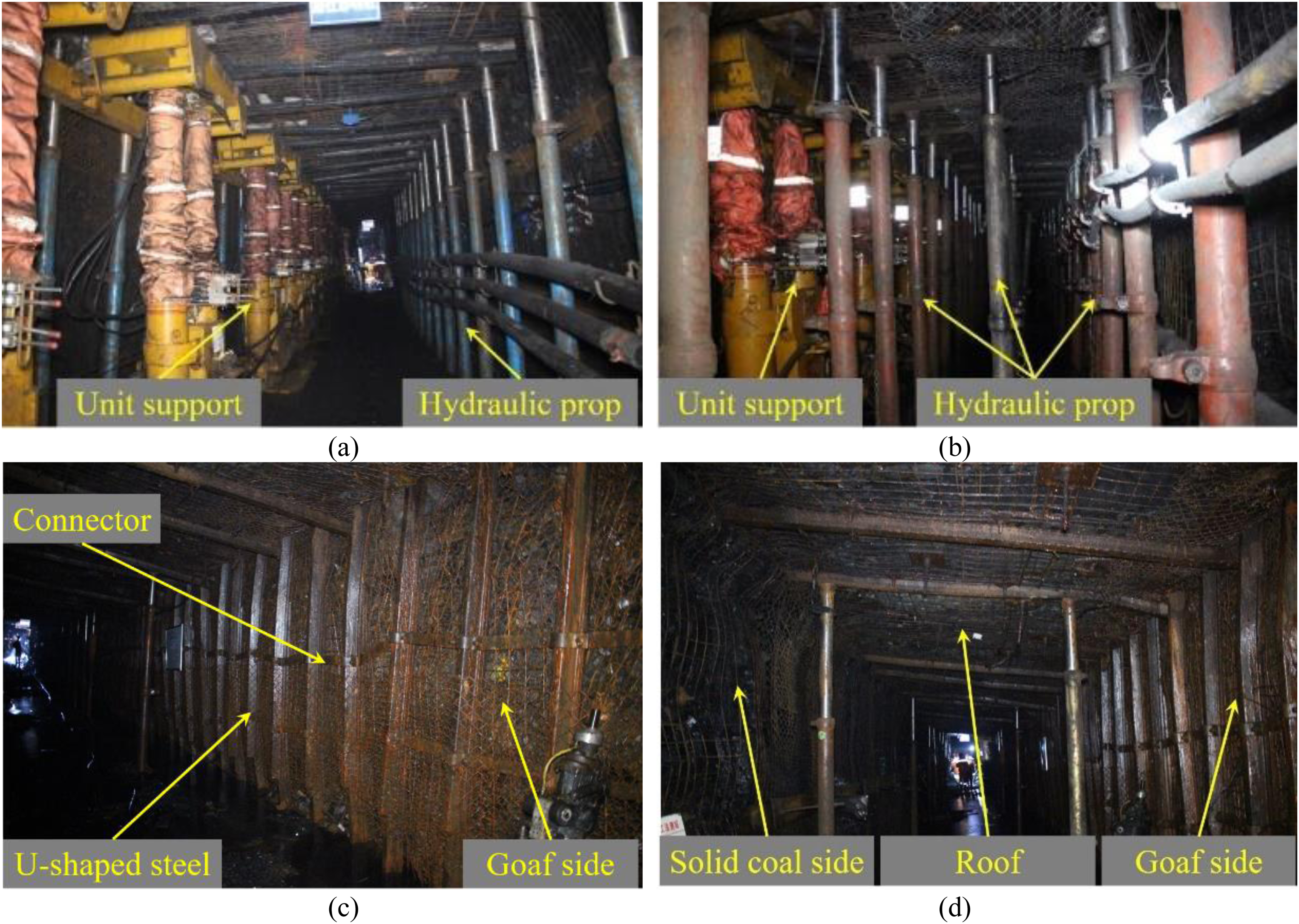
Effect of RFARC when the temporary support was withdrawn. (a) Temporary support effect before crossing ORCP (b) Temporary support effect after crossing ORCP (c) Goaf side. (d) Overall effect of roadway.
Conclusion
Under the influence of ORCP, there was a high stress concentration area in the stope. Before crossing the ORCP, the stress concentration in the working face increased firstly and then decreased, the stress gradually transferred to the both solid coal sides. The roof cutting had little influence on the stress distribution. The advanced mining stress began to be affected by the ORCP when it was 20 m away from the ORCP.
After crossing the ORCP, the stress values on both sides of the RFARC were smaller than the roadway without roof cutting. Besides, the roof and floor were in low stress area during the whole process of crossing ORCP. The peak value of the stress concentration in the solid coal side was gradually increased, and when the ORCP was lagged working face 80 m, the surrounding rock stress of RFARC tended to be stable.
The peak pressure of hydraulic support increased gradually when approaching the ORCP, and reached maximum when mining below the ORCP. The peak stress value closing to the roof cutting side was 4.34 MPa lower than that of non-roof cutting side.
Finally, a field reinforcement support and temporary support design of RFARC were proposed. The monitoring results of surrounding rock deformation showed that the deformation curve could be divided into three zones: rapid deformation zone, deceleration deformation zone and deformation stability zone. The rapid deformation zone below the ORCP was smaller, and the stability of surrounding rock was stable fast, but the deformation of the surrounding rock was largest, indicating that under the influence of the ORCP, the early movement of the surrounding rock was severe after mining, and the caving and compaction speed of the stope roof was fast.
Footnotes
Declaration of conflicting interests
The author(s) declared no potential conflicts of interest with respect to the research, authorship, and/or publication of this article.
Funding
The author(s) disclosed receipt of the following financial support for the research, authorship, and/or publication of this article: This work was supported by the Fundamental Research Funds for the Central Universities, the Open Fund of State Key Laboratory of Coal Resources and Safe Mining (grant number 2022YJSLJ09, SKLCRSM20KFA11).