
Abstract
This research study examines the integration of wireless system and solar cells for detection and location of faults in power grids by implementing minimum number of Phasor Measurement Units (PMUs) after considering zero injection buses. A fault in the grid networks indicates a failure in the entire network that interfaces the normal flow of current which can be measured using wireless systems. The fault location in power grid is problematic because of high existence in several lateral tap-offs. In addition, the identification of exact location with presence of faults in the power system and severity of the faults are challenging tasks due to bulk and complex nature of the electrical power system state estimation. The major requirement of PMU placement approach is to find the minimum number of PMUs and their location with maximum wireless coverage under fault conditions with a prerequisite for the projected algorithm. The integrated algorithm is tested and validated for different fault conditions where the results are compared with different conventional methods using different optimization models such as heuristics, decision rules and mathematical programming where the outcomes proves to be much effective in terms of number of PMU installation for proper placements and detection, location in number of fault systems thus achieving 82% reliability using Ant Lion Optimizer (ALO).
Scenario of grid integration- solar cells and wireless systems
The dynamic nature of power grids provides to new impacts in the operation of electrical power systems. Some topographies of these networks, such as distributed generation using renewable resources, changing load characteristics and increased reliability requirements, enlarging interconnections and deregulated energy markets, point out to the need for improved monitoring and control capabilities. Phasor Measurement Units (PMUs) offer coordinated measurements of voltage and current phasor at various locations, providing plentiful opportunities to estimate the state of a power network. The fault occurring in the system may affect the stability and observability of the power system. Due to the severe fault in the system, the system terminologies are tremendously varied. In recent days there are many challenges that are faced by electrical system engineers for identifying number of fault points in larger systems. If a large scale system is present then it is much difficult to find the tap-off point which indicates that estimation of such points are not properly connected with any laterals.
Because of this reason, the reliable technique has to be proposed to discern the status of the power networks more accurately. The subversive characteristics of grid systems that is used for generating power can be used without crossing the maximum voltage level for all connected bus systems in entire network. Hence incessant monitoring of entire grid system is necessary and it is a challenging task for electrical operatives. Basically, in a power system, there is a lack of adequate measuring devices to monitor the system. Owing to the cost reason, placement of the measuring instrument at all parts of the network is economically not feasible. To solve the above mentioned problem a optimal PMU placement scheme has been added which estimates all the corresponding states in the grid network with high accurate conditions. Even though various advantages are provided on installing PMUs in state estimation process, cost of deployment should be minimized. In line with above concern many developments have been made by several researchers for achieving full observable conditions at low installation cost
Literature review
The identification of exact fault location in the topology of different test systems are considered as the major tenacious complications in power system state estimation. The literature review unveils the exertion of minimum PMU placement with maximum redundancy, PMU outages, contingency analysis and calibration of the PMUs. In (Sobrinho et al., 2018) PMU placement is performed using a cost effective model where the features are limited in size for all power network operations which includes fuzzy modelling. All integrated techniques will be used for assessing necessary parameters that are used for identifying several disturbances that occurs frequently in power industries. This paper (Sobrinho et al., 2018) focussed only on cost optimized PMU for discerns the fault location but it may fails to cover the observability of the power network after post fault conditions. In (Adewole et al., 2016) the authors have focused on combining two different methods which are indicated as discrete wavelet transform and neural networks to identify various fault segments in entire network. The major disadvantage of above mentioned method (Adewole et al., 2016) is hardware dependence which means it require processor with parallel processing power, in accordance with their structure. For this reason, the realization of the equipment is dependent. The author in (Pignati et al., 2017) proposed a wide area backup protection scheme for 5 × 4. But it has some drawbacks with respect to accuracy and location of the faulted section. An efficient fault location method for large transmission networks has been discussed where the concept of matching degree (Prasad and Vinod Kumar, 2018) is defined which provides an effective index to reflect the effect of fault locations. But in this paper (Prasad and Vinod Kumar, 2018), the fault location approach uses two stages to identify the actual fault location due to this approach the computational time increased.
Further an efficient mechanism for identifying faults in transmission line systems by measuring voltage across wide area systems using network matrix has been identified (Della Giustina et al., 2014). But this type of voltage identification is not suitable for non-linear systems. As deliberated in (Pal et al., 2017), the PMU placement procedure to optimise the number of substations where installations must be made to observe all the buses when TPMUs as well as dual-use line relay branch-type PMUs (DULRPs) can be added into the network. The approach handles the additional constraints that all tap settings. Contrariwise the method (Pal et al., 2017) has an erroneous tap measurement or the presence of an unmeasured tap can lead to a huge error in the state estimation.
Furthermore, the author in (Wu et al., 2015), (Saha Roy et al., 2017) has projected an efficient algorithm using the ambiguity group theory to identify the locations of multiple outages with limited number of PMUs. Still identification of effective outages is concerned as a serious problem in both cascade networks and in terms of cost reduction. Subsequently location of faults are also identified using the underlying concept of transmission lines and an unique series is developed for designing three dimensional model with two circuits. For three dimensional designs a distinct model which measures voltage and current in synchronized way has been located with GPS technique (Saber et al., 2018). Since GPS technology is enabled two different faults can be identified which are termed as primary and secondary earth faults that happens in same location units. In case if the pole has been tripped then secondary earth fault will be considered but it is identified that location of two different faults is a complex process and more restrictions are present. Therefore in the next stage an optimization model is defined using two segments where matching degree index is provided for determining all the fault regions by reducing the exploration area thus short distance faults can be easily located.
Practically, due to budget restrictions (Jiang et al., 2012) PMUs cannot be installed with such density on transmission networks. The model proposed in (Das et al., 2017) is exactly the same for measuring only voltage level in the system using matrix type. Conversely, the only voltage measurement cannot give the accurate fault location (Das et al., 2017). Moreover, the PMU-based fault detection / location algorithms for double-circuit/three-terminal transmission line have been discussed in (Chen and Liu, 2003). Nevertheless, this method couldn’t be detecting accurate fault region if fault impedance is less. Also a unique framework to identify number of line outages with bad data measurements has been presented (Li et al., 2016) where the disadvantage of this framework (Li et al., 2016) is that it covers only observability constraint under multiple line outages and it fails to detect the location of fault and types of fault occurred in system. In (Wu et al., 2018), the load loss and reconfiguration after outage are considered with the relaying functions of metering devices in the OPP model. Initially, TPMUs and DULRs are used as verdict variables in the model to placate the observability constraints. In contrast, zero injection buses are not considered in the OPP model in (Wu et al., 2018).
Additionally, the fast and robust faulted line detection and fault location algorithm with minimum number of PMU voltage and current measurement had been projected in (Barman and Roy, 2018). Albeit, this method has identified fault in the large transmission system rather than the power network. Conversely the formulations for optimal PMU placements in presence of communicating infrastructure medium is used for minimizing delays in propagation for wide area systems (Appasani and Mohanta, 2018; Carvalho et al., 2018). But this problem formulation failed to identify location of faults in entire network. As deliberated in (Cui et al., 2019), the PMU-based event detection method by using the Swinging Door Trending (SDT) compression method and dynamic programming has been discussed. The SDT method for data compression is first used to compress the real-time PMU data into multiple compression intervals by the tuneable door width parameter. This type of early detection systems is having the possibility of raising false alarms where all unnecessary operations will minimize the economical benefits. For precise identification of fault in entire system support vector machine is introduced where transmission line faults that occurs in different locations can be identified using Fourier transform technique. Conversely the major disadvantage of the Fourier transformation (Mohanta et al., 2015) is the inherent compromise that exists between frequency and time resolution. By considering the aforementioned issues (Sobrinho et al., 2018; Adewole et al., 2016; Pignati et al., 2017; Prasad and Vinod Kumar, 2018; Della Giustina et al., 2014; Pal et al., 2017; Wu et al., 2015; Saha Roy et al., 2017; Saber et al., 2018; Jiang et al., 2012; Das et al., 2017; Chen and Liu, 2003; Li et al., 2016; Wu et al., 2018; Barman and Roy, 2018; Appasani and Mohanta, 2018; Carvalho et al., 2018; Cui et al., 2019; Mohanta et al., 2015), a new-fangled technique is introduced in power system line fault finding and localisation method for power grids, to precisely recognize and assess the location of the fault taking place anywhere in the network using PMU measurements.
Research gap and motivation
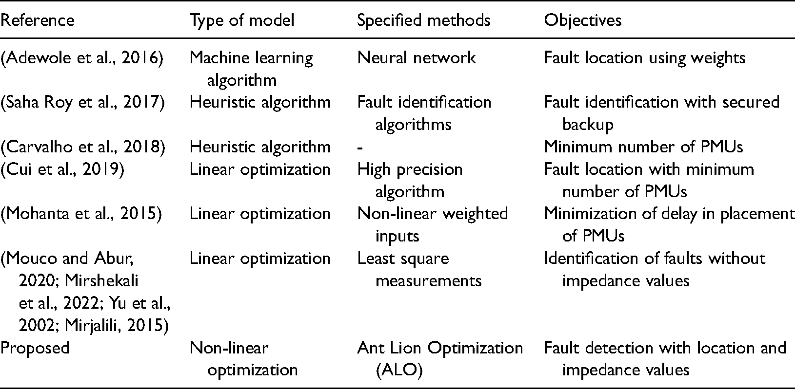
It has been reveal that all the preceding research work has been conceded in the optimal PMU placement with maximum coverage, PMU placement under various fault conditions, communication failure, topology expansion and prevention of data from the several data attacks as shown in the literature survey (Table 1). From the foregoing, it can be seen that many diagnostic approaches have been developed; nonetheless a perfect dependable and secure approach is still desirable. To the best of author’s knowledge, the most promulgated works, however fail to handle location identification of fault in power system. Therefore, the OPP placement in PSSE to identify the exact location of fault point has been implemented using ALO algorithm. It helps to identify the accurate faulty location and maintain the system observable and reliable.
State-of-the art analysis.
Objectives
There has been a significant research activity on the problem of finding the balanced and unbalanced fault location in terms of the voltage and current error by placing the PMU devices which is exposes that the literature survey. In the implemented case study line outage will be managed for extracting measurements in electrical quantity for real time networks that analyses the changes in location points. It is appropriate to stated that the lack of metering points in a typical power network presents a big challenge for fault locating methods. To solve the problems in location of faults and line outages a state estimation model is implemented where only minimum number of PMUs are selected for overcoming the shortcomings of metered points. To the author’s knowledge, there is no former study (Table 1) on this subject by placing the PMU device and identifying the accurate fault location in terms of calculating the error value of voltage and current parameters in power system state estimation.
Problem formulation
The objective for the minimum OPP problem is expressed as a nonlinear WLS minimization model and is given below,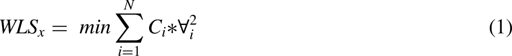

Discerning of fault location in power system topology
A symmetrical three phase short circuit is created at bus k through the fault impedance 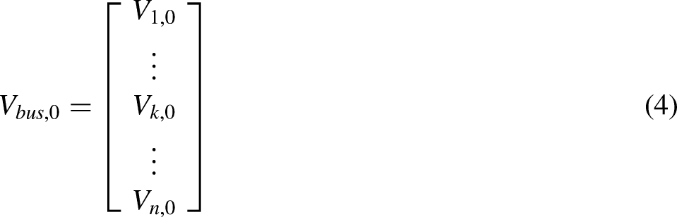
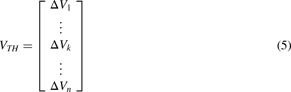

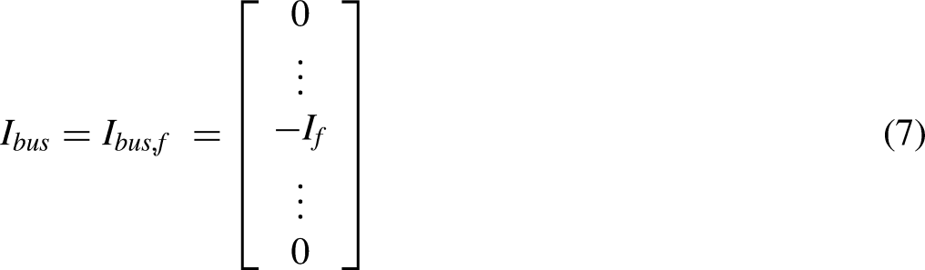

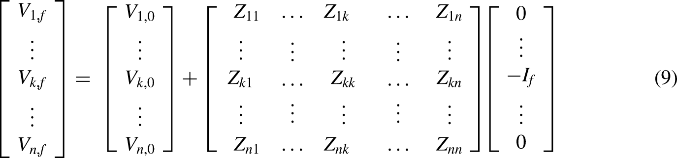

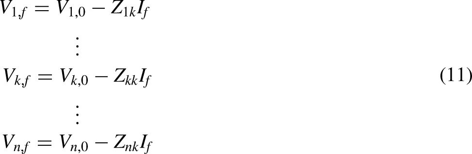


The interconnected sequence network, the sequence current can be computed as follows

Simulation setup
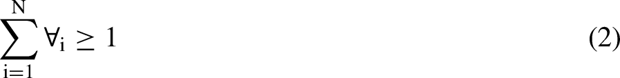
The ALO algorithm (Usman and Faruque, 2019) is used for minimizing the mechanism of hunting in all environments. The proposed model of PMU is based on quantitative analysis where there will be high interpretation of non-linearity in the system. In addition a more realistic real time implementation can be realized only if non-linear optimization is integrated. Moreover the data that is monitored is stored in the cloud with more number of variables and even conditions are present as defined in Equation (2). Once the non-linear optimization is introduced then all constraints are handled in a correct way where the conditions are converted to be operated in all unrestricted cases. Even the non-linear optimization is secured in such a way where n different decision variables are interleaved within feasible regions thus making the outcomes to be more reliable. Antlions originates from family of Myrmeleontidae which follows the order of networked insects. The life span of Antlions will be divided in to two different phases namely larvae and adult. The main characteristics of the aforementioned family are that huntiny mechanism usually happens at beginning stage during reproduction where it resembles the shape of cone. The contextual purpose for tunnelling is that when solution travels in a nearby medium then immediately decision will be reserved for future use. If the prey reaches near to the trap it will fall into the trap and it is try escape from the pit. The process of escaping mechanism happens by throwing sand to all the corner sides and in this case sliding mechanism will be applied at lowermost layer. In other case if the prey has been captured then the trapped prey will be pushed inside the soil and it will be disbursed for long period of time. If any additional wastage is found then it will be added in the next hunting mechanisms.
Outcomes and deliberation
All the simulation work have been developed in MATLAB platform and is executed on personal computer configured with Intel (R) core(TM) i3 – 5005U processor, 2.00 GHz, 4 GB RAM and 64 bit operating system. The test system particulars including line data and bus data are taken from (Mouco and Abur, 2020). For both test systems are fragmented.
Case 1: fault location identification based on the fault line
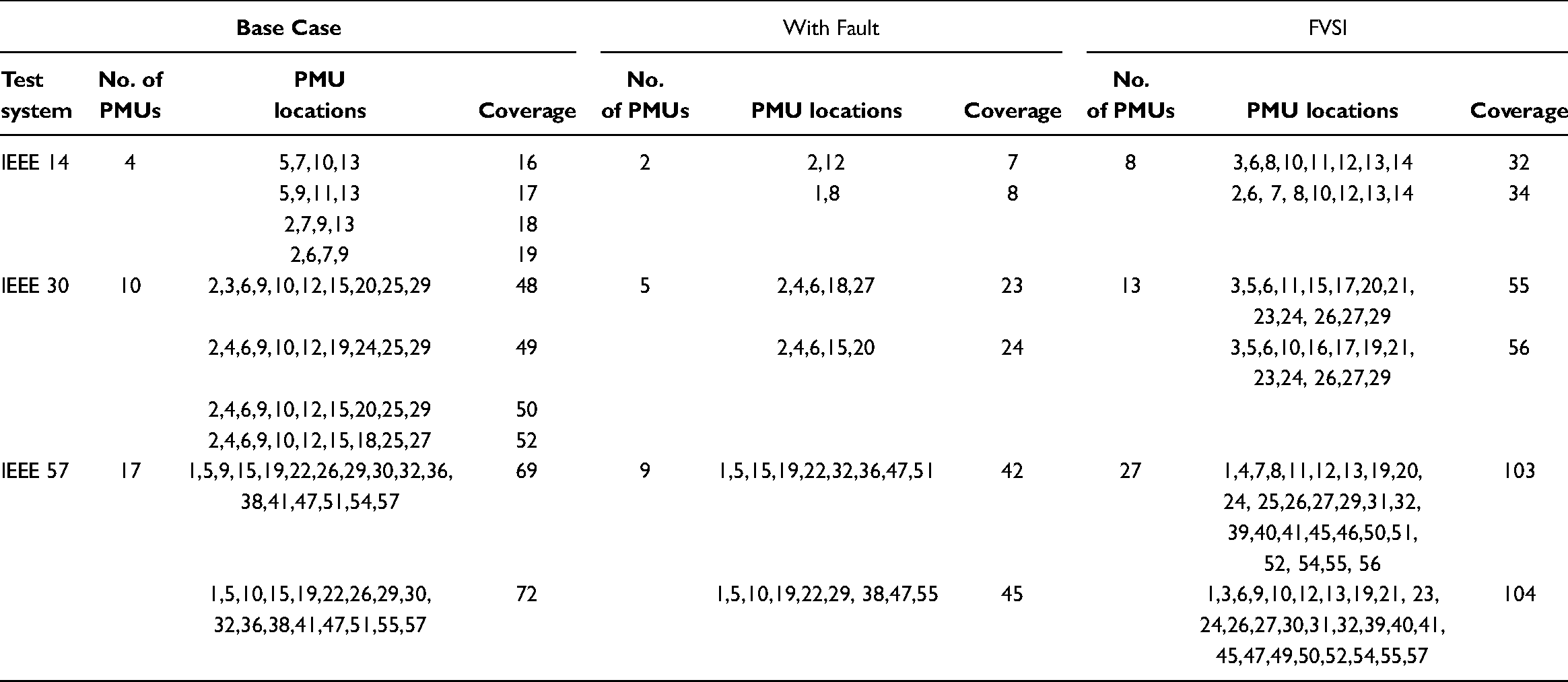
In PSSE, the PMU has been placed for system observability with maximum coverage and minimum PMU placements during the fault condition. The chosen standard IEEE test systems are low configured buses so that it can be treated as in power systems. The required minimum numbers of PMUs are installed in IEEE 14, 30 and 57 bus systems considering three scenarios which are base case, with fault condition and Fast Voltage Stability index (FVSI) for the complete observability of power system and its locations with coverage distance are given in Table 2. The ZI buses are the bus whose power injection into the network is zero which means it has no load or generator. By the way, the same number of PMUs is implemented in the network under the normal condition, fault condition and FVSI with maximum coverage. Even though the fault occurs in the power network, without adding or changing the number of PMU and location the maximum coverage has been obtained.
PMU placement for different test systems considering three scenarios.
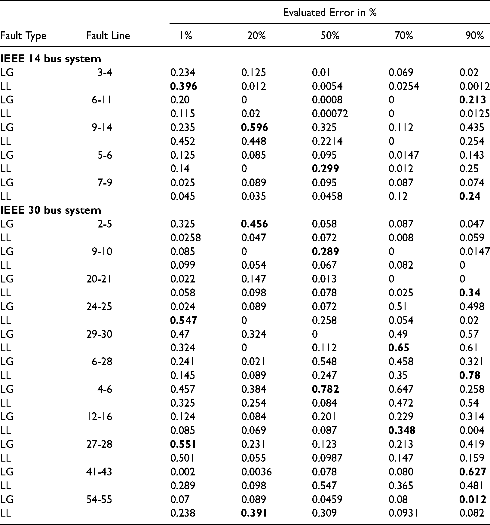
The load flow analysis has been simulated for the above said test case system and identify the overloaded line which is nothing but a fault line. Once the fault is identified in corresponding lines then location of faults will be simulated at five different points namely 1%, 20%, 50%, 70% and 90% for all types of transmission lines such as L-G, and L-L fault. Table 3 shows the error values obtained for different location and different types of fault of the various IEEE test systems. The highlighted error in the Table 3 gives the accurate error value of fault point with type of fault ensued in the test systems. For example, In case of IEEE 14 bus system, the two faults pretend in the line 3–4 in five different fault locations. In that, the highest error values are obtained in the 1% fault point with LL fault. Therefore, by the same way the error and fault point and nature of fault are identified. It can be seen that the error does not exceed 0.596% and 0.547%. It validates the accuracy of results obtained from the proposed algorithm. It can further be observed that in most of the cases, the average error increases as the fault occurs closer to any of the lines.
Evaluated error in different fault locations for different test systems.
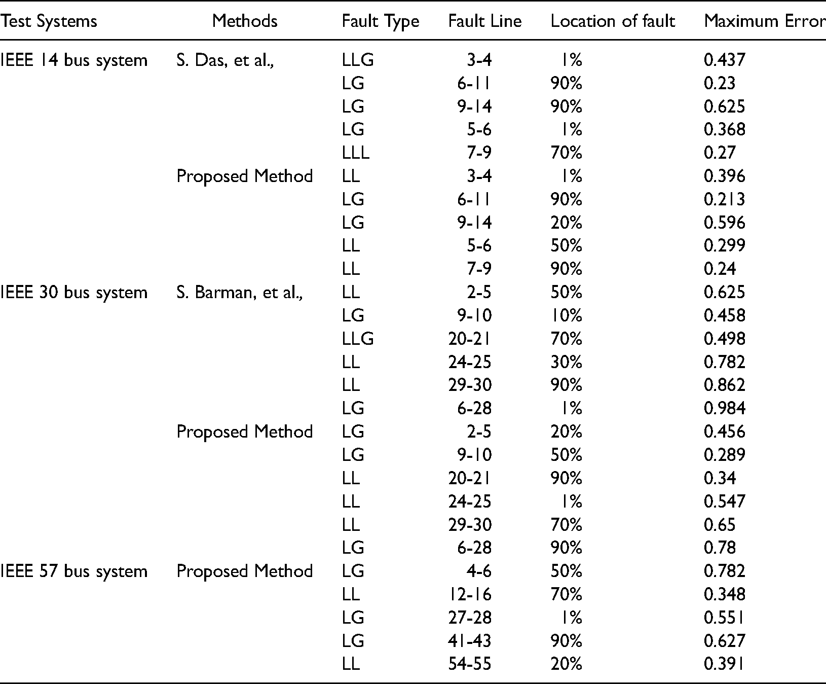
The comparison of the error values with existing error values (Das et al., 2017, Barman and Roy, 2018) are shown in the Table 4. From the comparison table, it can be easily understand that the minimum number of PMUs are installed in the network and identify the fault location and types of fault occurred in the system through the proposed efficient algorithm. In IEEE 14 bus system, there are five fault lines are identified which are 3–4, 6–11, 9–14, 5–6 and 7–9 and the corresponding error values for the fault line 6–11 is 0.213 which is much lesser than the existing value of 0.23 (Das et al., 2017). By comparing the all the fault line has lesser error value obtained which is more useful for identify the faulty line and location precisely. Similarly, the IEEE 30 and 57 bus systems have followed the same procedure and obtain the error values and optimum fault point.
Comparison of maximum error with fault location for proposed method.
Case 2: fault location identification based on the fault impedance
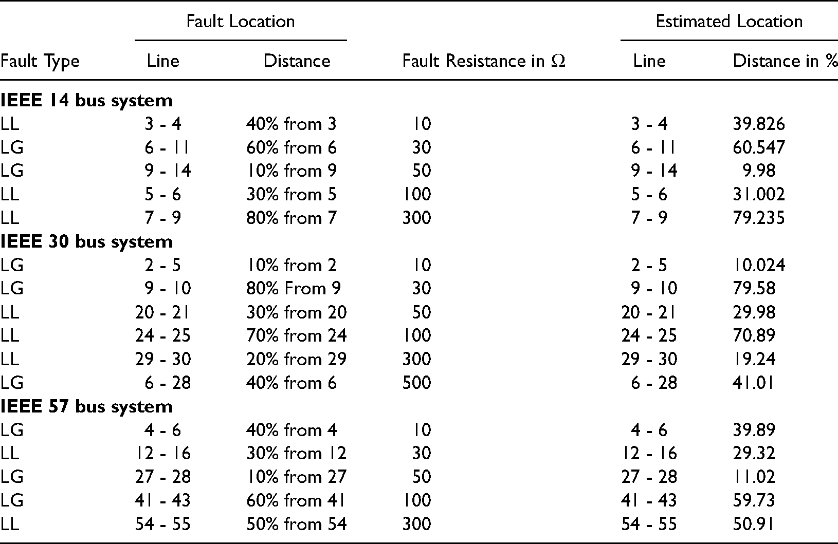
The projected algorithm is applied on the IEEE bus test system. It is assumed that the measurements taken are very accurate, and thus, the effect of measurement errors on the proposed algorithm is not considered. Table 5 shows the performance results of the proposed algorithm for various fault type and fault resistance. According to Table 5, it is clear that the fault location and estimated location of the fault almost same. For example, in case of IEEE 14 bus system, the distance fault location in the fault line 9–14 is 60% from the fault bus 6 with an impedance value of 30 ohm which is approximately equal to the estimated distance of fault location is 39.826%. Therefore, it can be understand the fault location distance and estimated fault location distance for the all fault line is nearly equal. Similarly, in IEEE 30 and 57 buses system has also the same result obtained. Although such high impedance faults rarely occur in practical cases. Still a study has been done to check whether the accuracy of the algorithm is affected by such high fault resistances. Many fault location algorithms proposed in the literature fails to locate faults with high resistances.
Simulation results for IEEE test system considering the increasing fault resistance.
Lg and LL fault results for IEEE test systems.
The algorithm proposed in this paper is independent of fault resistance. This proves the superiority of the proposed algorithm.
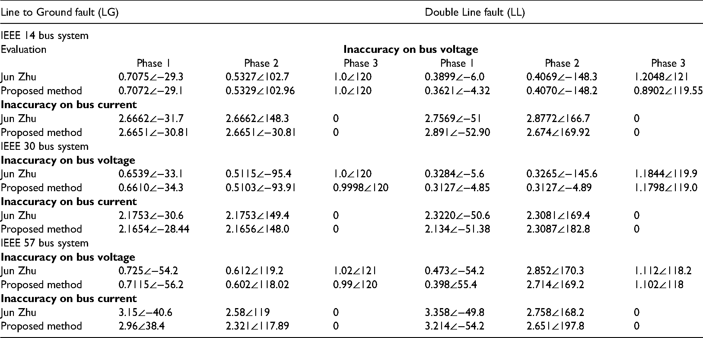
Case 3: fault location identification based on the inaccuracy on voltage and current
In order to validate the phase domain method, the results of this approach will be compared with existing method. In this case, all the transformers are assumed to be connected in Y-Y with both neutrals grounded. All the line shunt capacitances will be omitted and all the pre-fault voltages are set as 1 per unit. The zero sequence impedances are set as three times of the corresponding positive sequence impedances. Different fault types will be checked.
The test results are listed in Tables 5 for the various fault condition of IEEE 14, 30 and 57 bus systems. From the both Tables 4 and 5, it can be understand that the inaccuracy value of voltage and current for the three phases has been obtained lesser value. From the results presented above, the errors of the conventional methods are higher phase values of voltage and current which prove that the proposed algorithm is correct for the fault calculation. In the proposed method it is possible to integrate other optimization techniques such as heuristics, mathematical programming and decision rules. But as compared to the non-linear optimizer that is introduced in the proposed method the abovementioned types has their own drawbacks such as in heuristics it is much difficult to obtain achieve optimal solutions as the lines are too far to be connected and even if any new environment is detected then it is much difficult to be adapted. In addition if mathematical programming is used then large scale conditions cannot be formulated and even the type of formulations are not present in compatible mode when it is connected with other systems. But decision rule is better as compared with other two optimization process but all the variables must be updated in a time based conditions.
Conclusions
A fault location scheme for power system state estimation has been presented in this paper. Synchronized voltage and current measurements in the phase domain are employed for faulted line branch identification and fault classification, as well as fault location. The proposed scheme is suitable for the sustainable energy and developing the network towards smart decision. Further the projected approach enhances the system performance by increasing the reliability by identifying different types of fault, initiation angles and error values due to fault conditions. For all power network faults, the faulted line branch is easily identified with high efficiency and all fault types including normal shunt faults, evolving faults, and cross-country faults are distinguished from each other. In addition, the outcomes are examined under two case studies where the faults are examined using fault lines and impedance and in both cases maximum estimation error in fault location does not exceed 0.5%. Moreover the percentage of reliability in detecting the faults is much higher and it is above 62 percentage whereas the total accuracy of proposed method is 82 percentage. In future the proposed method can be expounded by integrating multiple objectives that further minimizes the number of faults in the entire system and in addition the system setup can be modified by integrating machine learning algorithms.
Footnotes
Declaration of conflicting interests
The author(s) declared no potential conflicts of interest with respect to the research, authorship, and/or publication of this article.
Funding
The author(s) received no financial support for the research, authorship, and/or publication of this article.