
Abstract
The tight heterogeneous glutenites are typically characterized by highly variable lithology, low/ultra-low permeability, significant heterogeneity, and a less-developed natural fracture system. It is of great significance for economic development to improve hydraulic fracture complexity and stimulated reservoir volume. To better understand the hydraulic fracturing mechanism, a large-scale experimental test on glutenite specimens was conducted and the hydraulic fracture propagation behaviors and focal mechanism were analyzed. A three-dimensional numerical model was developed to reproduce the hydraulic fracture evolution process and investigate the effects of operating procedures on hydraulic fracture geometry and stimulated reservoir volume. A simultaneous variable injection rate and fluid viscosity technology was proposed to increase the hydraulic fracture complexity and stimulated reservoir volume. The results indicate that four fracturing behaviors can be observed, namely, penetration, deflection, termination, and bifurcating, in the laboratory experiment. Tensile events tend to appear during the initiation stage of hydraulic fracture growth, while shear events and compressive events tend to appear during the non-planar propagation stage. The shear and compressive mechanisms dominate with an increase in the hydraulic fracture complexity. The variable injection rate technology and simultaneous variable injection rate and fluid viscosity technology are effective techniques for fracture geometry control and stimulated reservoir volume enhancement. The key to improve hydraulic fracture complexity is to increase the net pressure in hydraulic fractures, cause evident pressure fluctuations, and activate or communicate a wide range of natural discontinuities. The results can provide a better understanding of the fracture geometry control mechanism in tight heterogeneous glutenites, and offer a guideline for treatment design and optimization of well performance.
Keywords
Introduction
Glutenite reservoirs are widely distributed throughout the world, including the Los Angeles Basin in North America, the Argentine Basin in South America, and the Bohai Bay Basin in Eastern China. The development of glutenite reservoirs has attracted wide attention in recent years (Chen et al., 2020; Ju et al., 2018). The tight heterogeneous glutenite reservoirs are typically characterized by high variable lithology, low/ultra-low permeability, poor pore connectivity, and significant heterogeneity. This type of reservoir is generally not suitable for commercial production without hydraulic fracturing (Li et al., 2013).
Extensive studies have investigated the propagation mechanism of hydraulic fractures (HFs) in tight heterogeneous glutenites based on numerical simulations and laboratory tests. Li et al. (2013) simulated the hydraulic fracturing process using a two-dimensional (2D) numerical model and summarized five fracturing behaviors when a fracture approaches a gravel particle, namely, termination, penetration, deflection, branching, and attraction. Rui et al. (2018) conducted 2D numerical simulations to investigate the influence of rock mechanical parameters and gravel property on the HF propagation, and indicated that the HF geometry is controlled by reservoir physical and mechanical parameters, in-situ stress, and operational parameters. Ju et al. (2018) studied the hydraulic fracturing behaviors of heterogeneous glutenites and their influencing mechanisms using 3D numerical simulation based on bonded particle models and suggested that gravels in heterogeneous glutenites inhibit crack propagation. Ma et al. (2017) investigated the growth law of HFs in glutenite reservoirs based on laboratory experiments and examined the effects of gravel size, horizontal differential stress, fluid viscosity, and injection rate on the HF growth behaviors. However, in these studies, the HF propagation, especially the focal mechanism, was still not fully understood. Moreover, most of the present research studied the hydraulic fracturing mechanisms in tight heterogeneous glutenites at a laboratory scale, while little research studied them on a field scale. The conclusions drawn from experiments and simulations in the laboratory scale cannot be directly used in field operations due to the scale effects (Tan et al., 2017). Therefore, it is of great significance to carry out field-scale numerical simulations to optimize the operating procedures and provide guidance for fracturing design and field operation.
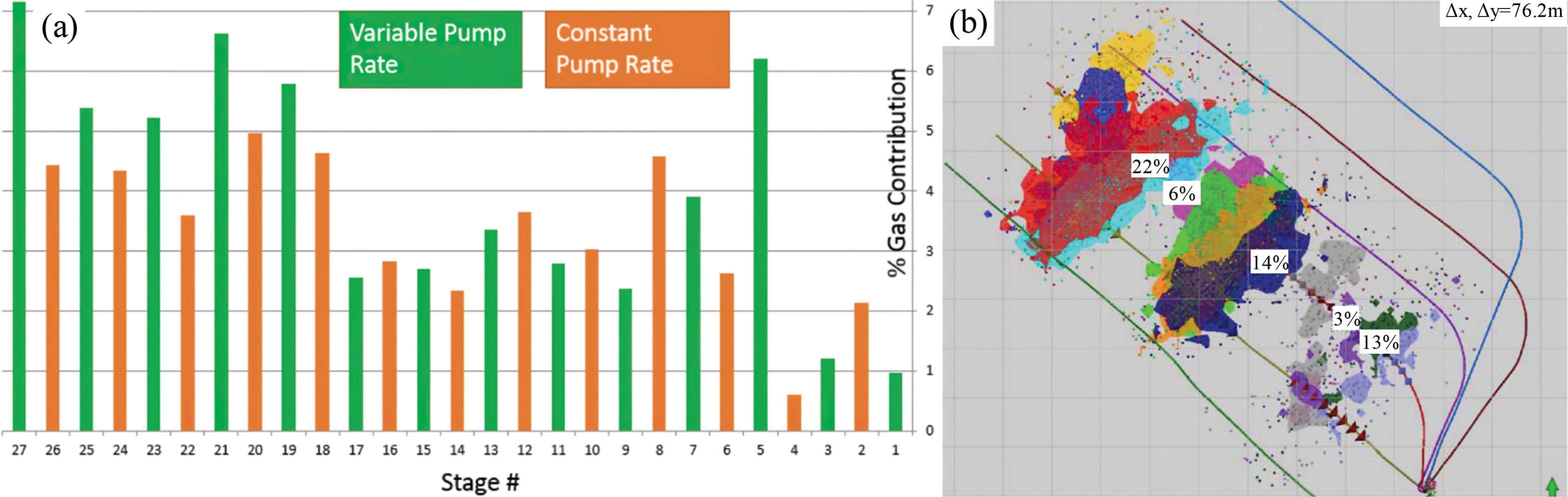
Considerable effort has been directed toward the new hydraulic fracturing techniques, such as variable injection rate fracturing and alternate fluid injection fracturing, and has obtained remarkable treatment effects (Ciezobka et al., 2016; Hou et al., 2014; Kao et al., 2019). Using optimized hydraulic fracturing technologies, such as refracturing technology, volumetric fracturing from horizontal wells, and temporary plugging, the glutenite reservoirs in the Junggar basin, China have been successfully developed (Zhu et al., 2021). The HF geometry is significantly affected by the in-situ stress state and its variations. Due to the strong heterogeneity and complex in-situ stress environment of glutenite reservoirs, the growth mechanism of HFs is complicated and the HF geometry is quite tortuous. There is a competition between in-situ stress contrast, fracture net pressure, and injection rate, which in turn determined fracture curvature in an altered stress field (Safari et al., 2016). Hou et al. (2014) suggested that the variable injection rate fracturing can form pressure pulses in the reservoir and help activate natural fractures and create a complicated HF network. The key to variable injection rate fracturing technology is to determine the timing of displacement change and the choice of displacement range according to the different reservoir geological conditions. Ciezobka et al. (2016) compared the microseismic (MS) data and production data between variable injection rate stages and the constant injection rate stages of Marcellus shale, as shown in Figure 1, and indicated that a 19% increase in production for the variable injection rate stages versus the constant injection rate stages. The MS event count of variable injection rate stages is higher than that of constant injection rate stages, which indicates the HF complexity of variable injection rate stages is higher than that of constant injection rate stages. Field data proved the superiority of variable injection rate fracturing. Kao et al. (2019) conducted an experimental study on the influence of alternate fluid injection modes on HF geometry of deep shale and indicated that alternate injection of high-viscosity fluid followed by the low-viscosity fluid could form the fracture pattern of main fracture and branch fractures; while alternate injection of low-viscosity fluid followed by the high-viscosity fluid only opened fractures near the wellbore, and was not conducive to the extension of the main fracture. The application of volume fracturing in shale reservoirs indicated that the natural fracture system is the critical factor contributing to the formation of complex fractures/fracture networks, opening and connecting natural fractures are the key to improve the fracturing performance (Dehghan et al., 2015). Although natural fractures in tight heterogeneous glutenites are not as developed as those in shale and coal reservoirs, the widely distributed gravels and the interface between gravels and matrix have a positive influence on the non-planar propagation of HFs, which is conducive to the formation of complex HFs. Tight heterogeneous glutenites have low permeability and small oil drainage radius, the key to improving productivity is to increase stimulated reservoir volume (SRV) and connect with larger storage space through a fracture network. Therefore, it is necessary to achieve design goals through optimizing operating procedures. Ishteiwy et al. (2016) indicated that creative operational solutions must be constantly sought to facilitate the development of increasingly difficult reserves through stimulation operations. However, there are currently few relevant explanations to reveal the mechanism of HF geometry control and elaborate on how to formulate an optimal injection strategy to maximize SRV for tight heterogeneous glutenites.
(a) Production logging results for a well across producing clusters and (b) typical hydraulic fracture stage in the Marcellus shale and microseismic (MS) event density during injection of the hydraulic fracture stage. Overlaid on top are production log results with production contribution for selected frac stages. (The figure is redrawn according to the study of Ciezobka et al., 2016).
In this paper, the large-scale true triaxial simulation experiment on glutenite specimens was carried out to study the propagation behaviors and the focal mechanism of HFs. A three-dimensional (3D) numerical model based on RFPA3D was then developed to reproduce the HF evolution process and evaluate the effects of injection procedures on HF geometry and SRV. The numerical model is built based on field monitoring data and laboratory test results, and verified by MS monitoring data. The effects of variable injection rate mode on HF geometry and SRV were evaluated based on numerical simulations. A simultaneous variable injection rate and fluid viscosity technology was proposed for the enhanced stimulation of tight heterogeneous glutenites. The results of this research provide a better understanding of the formation mechanism of complex HFs in tight heterogeneous glutenites and offer theoretical support for fracture geometry control and optimization of hydraulic fracturing design.
HF propagation mechanism in tight heterogeneous glutenites
Engineering background
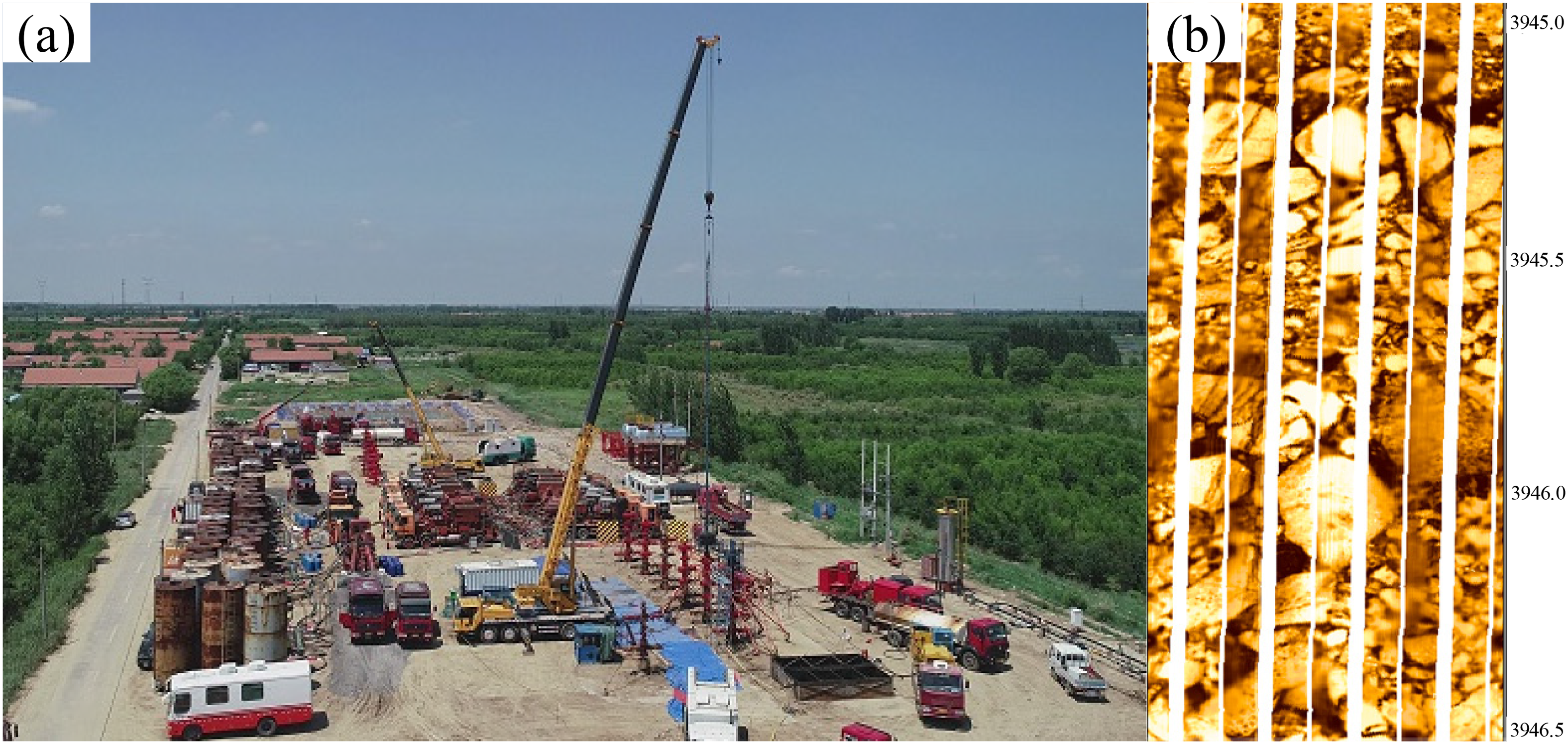
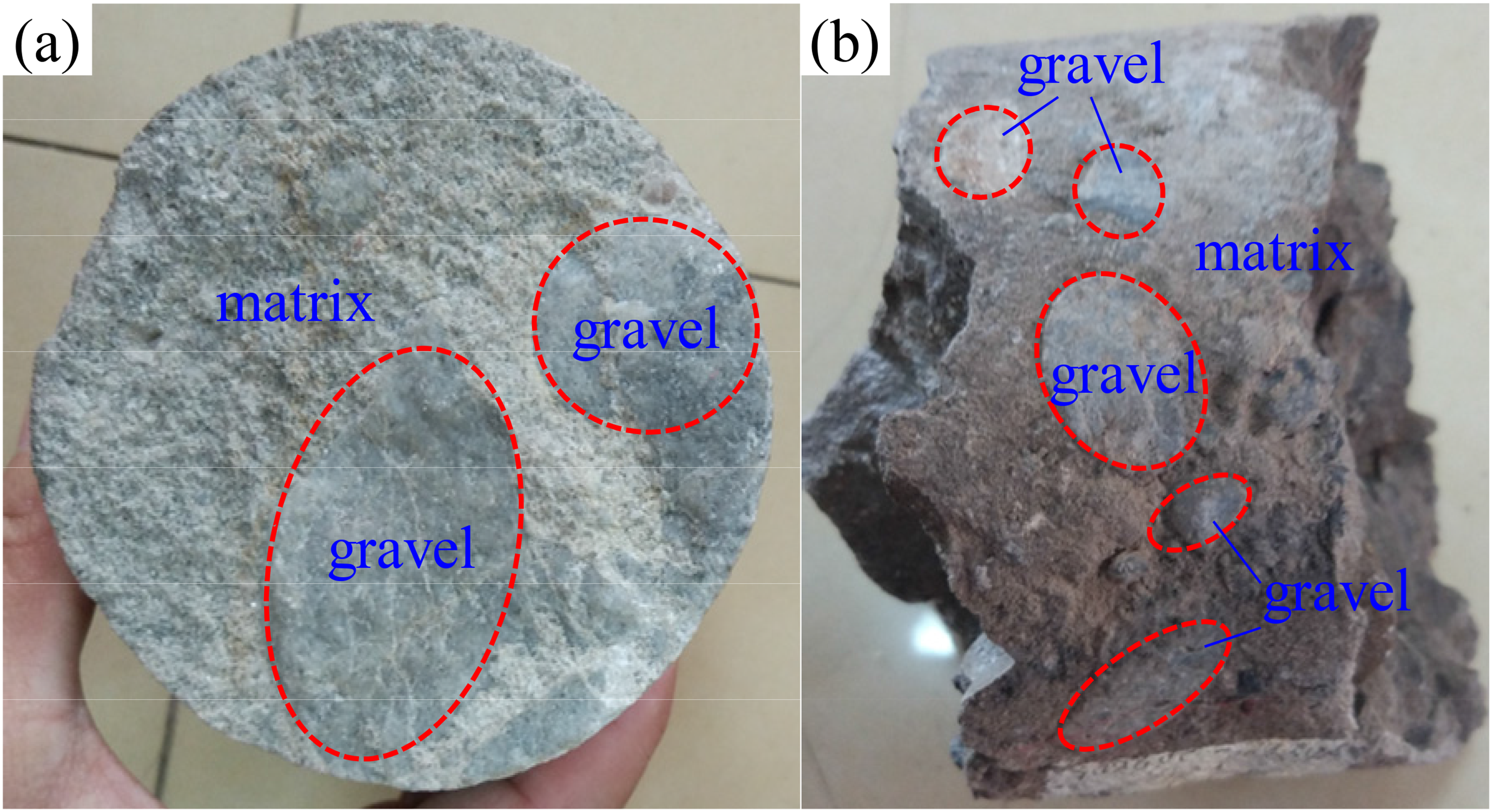
The tight heterogeneous glutenites of Shengli Oilfield are located in Jiyang depression, Bohai Bay Basin, eastern China. The exploration area is nearly 1500 km2 and the potential oil and gas reserves were found to exceed 450 million tons. The oil and gas development of deep tight heterogeneous glutenites has become the focus of fossil energy exploitation in Shengli Oilfield. Figure 2 shows the hydraulic fracturing operation field of Shengli Oilfield and the Formation Microscanner Image of tight heterogeneous glutenite. The natural fractures of tight heterogeneous glutenites are not as developed as those in other sedimentary reservoirs such as shales and coals, which is not conducive to the formation of fracture networks (Grasselli et al., 2015; Xiang et al., 2019; Zou et al., 2016). Figure 3 shows the geometry of glutenite cores drilled from a well in Shengli Oilfield, gravels of different sizes and contents can be observed in the glutenite cores.
(A) The hydraulic fracturing operation field of Shengli oilfield and the Formation MicroScanner Image (FMI) of tight heterogeneous glutenite.
The geometry of glutenite cores drilled from a well in the Shengli oilfield.
Field operation experiences indicate that simple bi-wing HFs are typically generated in tight heterogeneous glutenites in Shengli Oilfield with conventional fracturing technology, which may lead to a rapid decline in productivity after fracturing and poor economic benefits. With the development of fracturing technology, Shengli Oilfield is no longer satisfied with the traditional bi-wing HFs and has attempted to optimize injection strategies to create complex HFs and improve SRV (Behnia et al., 2015; Zhang et al., 2019; Zhou and Ma 2020). To achieve this, it is necessary to understand the fracture propagation mechanism and optimize the treatment procedures and stimulation technology. The factors that affect the fracturing performance of tight heterogeneous glutenites can be classified into two categories: uncontrollable factors (i.e. geomechanical conditions) and controllable factors (i.e. fracturing operations) (Cipolla et al., 2010). The geomechanical conditions such as in-situ stress, volume content of gravels, and mechanical properties of glutenite cannot be possibly changed, but we can improve fracture complexity and maximize SRV by optimizing the operating procedures and corresponding treatment parameters, such as injection rate and fluid viscosity. A successful fracturing operation is to find the optimal combination of geomechanical conditions and fracturing operations.
Experimental equipment and procedures
The large-scale hydraulic fracturing simulation test was conducted on a self-developed true triaxial hydraulic fracturing test system, as illustrated in Figure 4. The system consists of four main parts, namely, (1) a true triaxial servo loading system, (2) a fluid injection servo control system, and (3) an automatic data acquisition and processing system. A cubic specimen with maximum allowable dimensions of 300 mm is placed in the test frame surrounded by pressurizing pistons. The three in-situ stresses were loaded independently using the true triaxial assembly. The confining stresses could be loaded up to 10 MPa. The fluid injection servo control system was used to accurately determine the injection rate and injection pressure. The maximum injection rate and injection pressure are10 ml/min and 40 MPa, respectively. The acoustic emission (AE) monitoring system, manufactured by an American acoustic company, was applied to analyze the focal mechanism of glutenite fracture, as presented in Figure 5. Eight AE probes were used in the AE monitoring system to obtain the AE signals associated with the initiation and extension of the HFs.
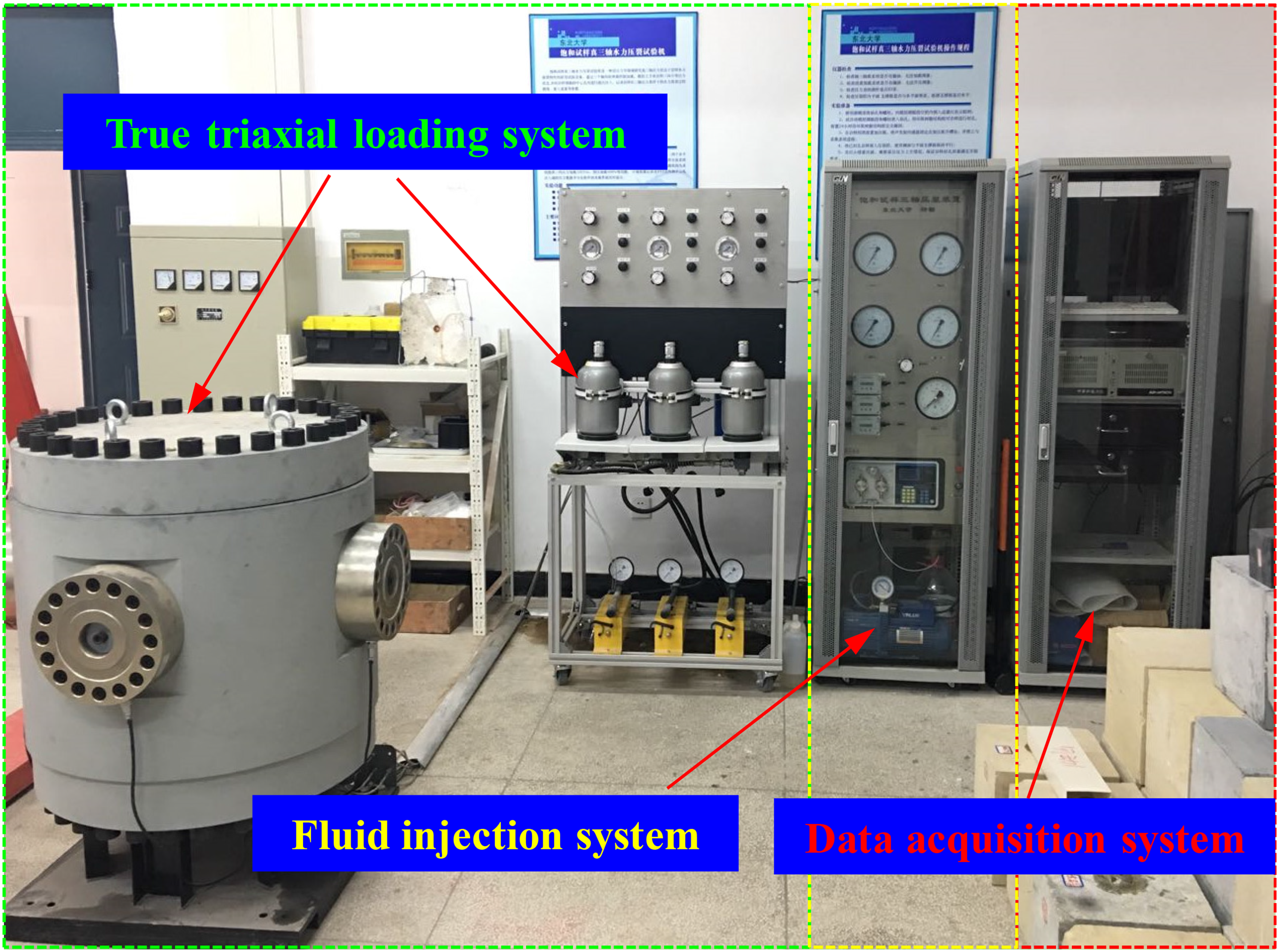
True triaxial hydraulic fracturing simulation test system.
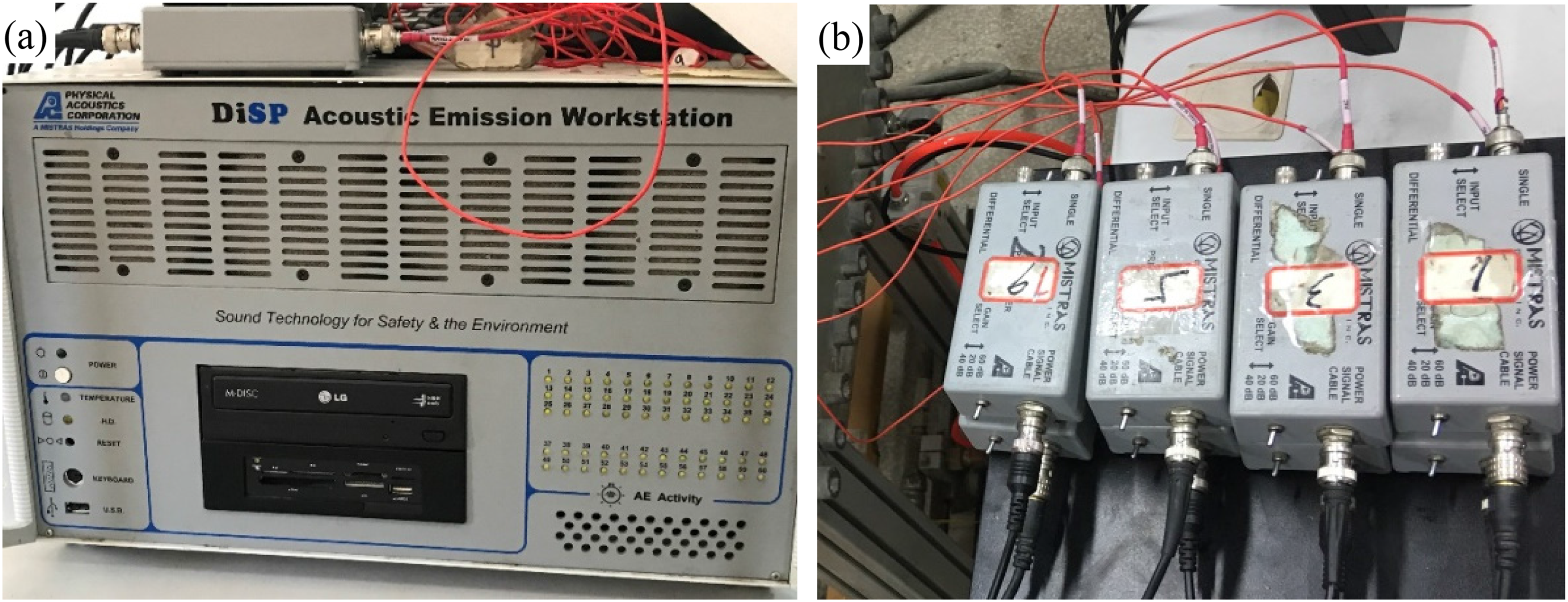
The acoustic emission (AE) system: (a) AE workstation and (b) amplifier.
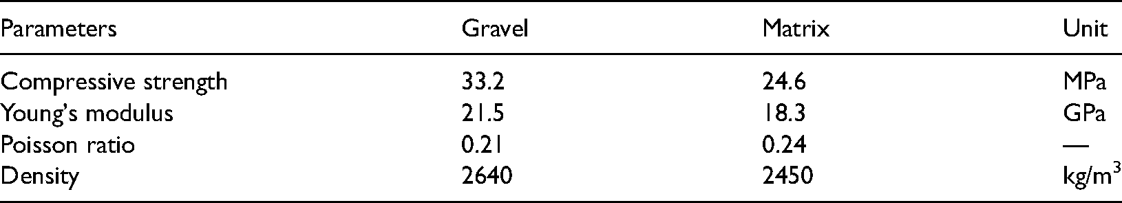
A 300 mm × 300 mm × 300 mm cubic concrete block is chosen as a specimen. Figure 6 shows the glutenite specimens preparation process. The cement specimens are made of 40- to 80-mesh quartz sand and 42.5 R composite Portland cement mixed in the weight ratio of 1:1. The mortar is poured into a 300 mm × 300 mm × 300 mm square mold vessel. The concrete block will be ready for use after four weeks of curing time. The manmade wellbore was simulated by high-strength steel tubes with internal and external diameters of 15 and 20 mm, respectively. The manmade wellbore is 165 mm in length. The heterogeneous glutenite model is formulated by adding gravels to the concrete. The size of gravel varies from 5 to 75 mm. The gravels of different sizes are randomly distributed in the concrete with a mass content of 35%. The physical and mechanical parameters of gravel and matrix are listed in Table 1.
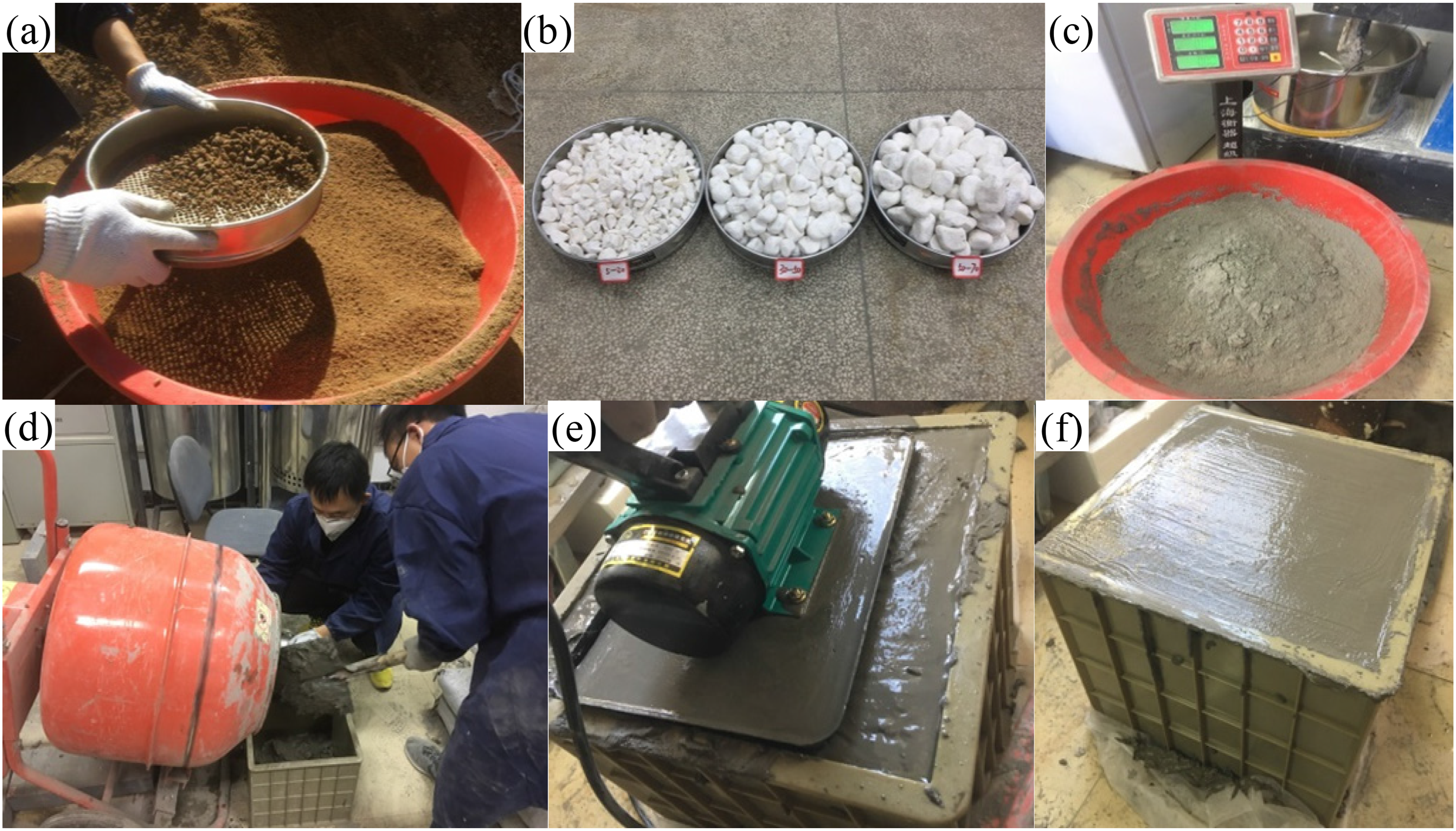
Glutenite specimens preparation process: (a) sand screening, (b) gravels of different size grades, (c) cement weighing, (d) mixing the water and sand into the cement, (e) vibration, and (f) molding and curing.
The physical and mechanical parameters of gravel and matrix.
First, the glutenite specimen was placed in the true triaxial test frame, and the AE probes were attached at the eight points on the glutenite cube through the prefabricated placing holes on the loading plates, as shown in Figure 7(a). Second, the equipment was assembled, and the triaxial stresses were loaded, as shown in Figure 7(b). The vertical stress, maximum horizontal stress, and minimum horizontal stress were 8, 6, and 3 MPa, respectively. Third, the fluid injection servo control system was started and the water was injected into the glutenite specimen through the wellbore at an injection rate of 5 ml/min to induce fracturing. The injection time is 28 min. A red-colored agent was added to the water as a tracer for a better observation of the HFs. At the same time, the AE monitoring system and data acquisition and processing system were started to obtain the AE events and record the injection pressure curves. When the water flowed out from the triaxial cell and injection pressure decreased to a stable value, the fluid injection system was shut in and the test was over.

Assembly of glutenite specimen: (a) attaching acoustic emission (AE) probes and (b) placing the glutenite specimen into a triaxial servo loading system.
HF propagation behaviors
Large-scale physical simulation experiments were conducted to analyze the HF propagation behaviors and focal mechanism, and estimate the possibility of complex HF generation. Figure 8 presents the HF propagation modes in the glutenite specimen. The HFs in the glutenite specimen are tortuous, which may be caused by the strong heterogeneity of the matrix and the presence of gravels. Four fracturing behaviors can be observed, namely, penetration, deflection, termination, and bifurcating, in the laboratory experiment. The attraction behavior observed in the numerical simulation is not easily observed in physical simulations (Li et al., 2013). The penetration mode tends to appear around the wellbore, and the termination and deflection mode tends to appear away from the wellbore. The glutenite is more difficult to form a fracture network than shale and coal, due to the discontinuity of natural fractures. Nonetheless, the complex propagation behaviors of HFs when encountering gravels may contribute to the formation of complex fractures, especially in glutenite reservoirs with high gravel contents. The existence of gravels and mechanically weak structures may complicate the pore pressure field and stress field, HF growth may change its initial path and follow the local path with the least resistance.
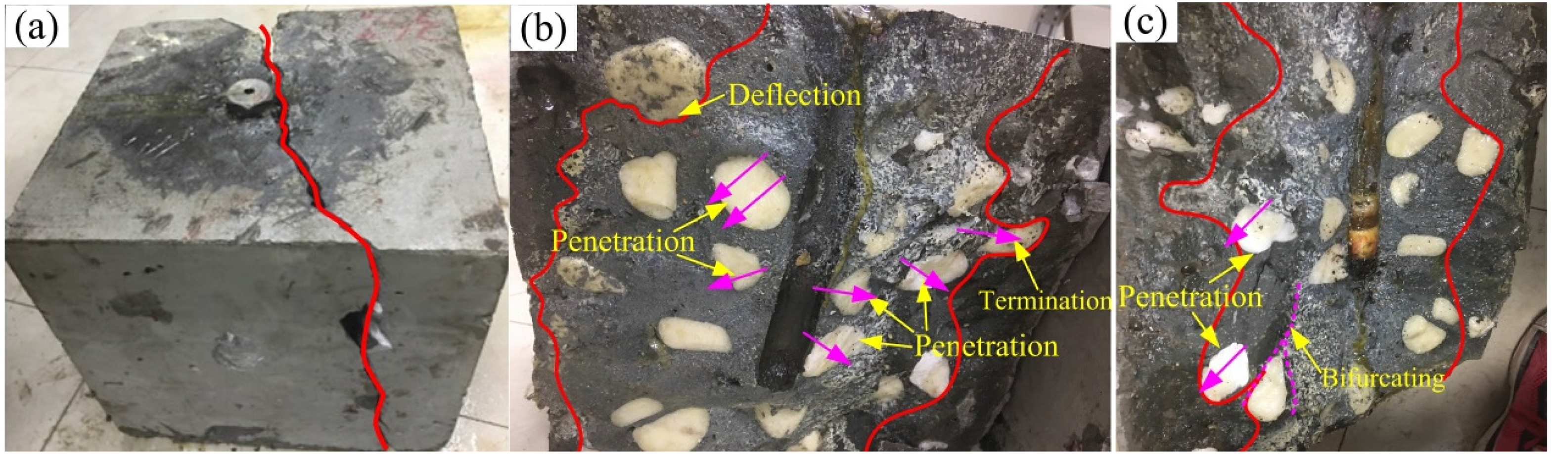
Hydraulic fracture (HF) propagation modes in glutenite specimen.
Focal mechanism analysis
To compare the focal mechanism of HFs in glutenite at different scales, the AE events obtained from laboratory physical experiments and MS events obtained from field fracturing monitoring are analyzed using the moment tensor inversion method. The results of the focal mechanism analysis are illustrated in Figure 9. It can be concluded that the seismic responses of complex HF initiation and propagation in both laboratory scale and field scale appear to be similar. Tensile events tend to appear during the initiation stage of HF growth, most are located around the wellbore. While shear events and compressive events appear primarily around the branch fractures and non-planar propagation fractures, most are located away from the wellbore. Shear and compressive mechanisms generally dominate with an increase in the HF complexity. According to the distance between the fractures and the wellbore, the complex HF is composed of three types of fractures in scale: one is the propped main fracture, which is the main channel for oil and gas flowing to the wellbore; the second is the self-supporting fracture formed by the shear slip of the natural fractures, which depends on the development of the natural fractures and forms a large stimulated volume; the third is the capillary fractures, which connect the micro nanopores and natural cracks of the reservoir. From the results of MS interpretation, it can be seen that the tensile fractures near the wellbore should be the main fracture that can be propped; the shear fractures and mixed fractures are the secondary fractures, that is, the self-supporting fractures induced by the shear slip of natural discontinuities. The tertiary capillary fractures may not respond to the MS data.
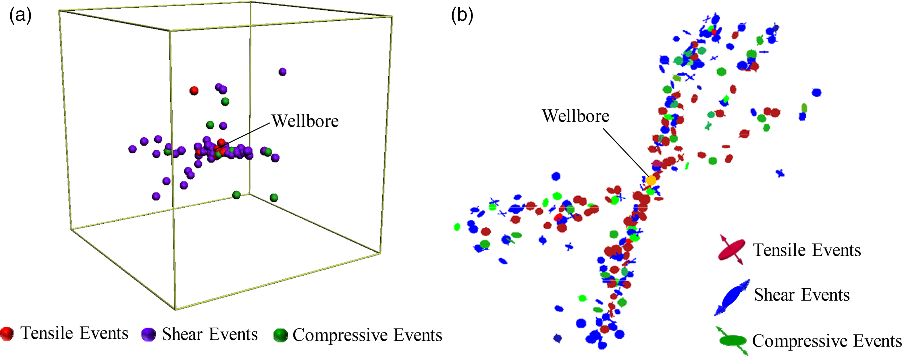
Focal mechanism of (a) AE events from the laboratory scale physical model and (b) MS events from field-scale fracturing of Y560 block tight heterogeneous glutenites.
The tight heterogeneous glutenites in Shengli Oilfield are characterized by poor physical properties, low/ultra-low permeability, significant heterogeneity, and a less-developed natural fracture system, which result in various challenges in reservoir development. Traditional cognitions believe that natural fractures such as joints, bedding planes, and microcracks are the fundamental conditions for the formation of complex fractures and fracture networks (Guo et al., 2014; Hou et al., 2014). Although the natural fractures in glutenites are not as developed as those in shales and coals, the geological characteristics of tight heterogeneous glutenites such as strong heterogeneity and the presence of gravels of different sizes and volume contents make it possible to form complex fractures. According to the fracture propagation behaviors and the focal mechanism of complex HFs in tight glutenites, coordinating the operating procedures may contribute to increasing the HF complexity. Creating more tensile fractures and increasing the turning radius of secondary fractures around the wellbore in the early stage of fracturing, and inducing more matrix/gravel interfaces to shear and slip or increasing the proportion of shear fractures and compression fractures in the area away from the wellbore will be beneficial for increasing SRV.
Figure 10 presents the schematic diagram of complex HF propagation behavior in tight heterogeneous glutenites. The HF geometry of tight heterogeneous glutenites is jointly determined by in-situ stress state, mechanical properties of gravel and matrix, gravel distribution characteristics, and treatment conditions. The existence of gravels and mechanically weak structures provides a fundamental basis for complex HFs generation. The glutenite reservoirs with high gravel content and high weak plane density are more likely to generate complex HFs. However, field operation experience indicated that conventional fracturing technology can only create simple straight fractures or X-shaped complex fractures. To create a more complex HF, it is necessary to reasonably design the injection procedure and induce more secondary and tertiary branching fractures, as shown in Figure 9.
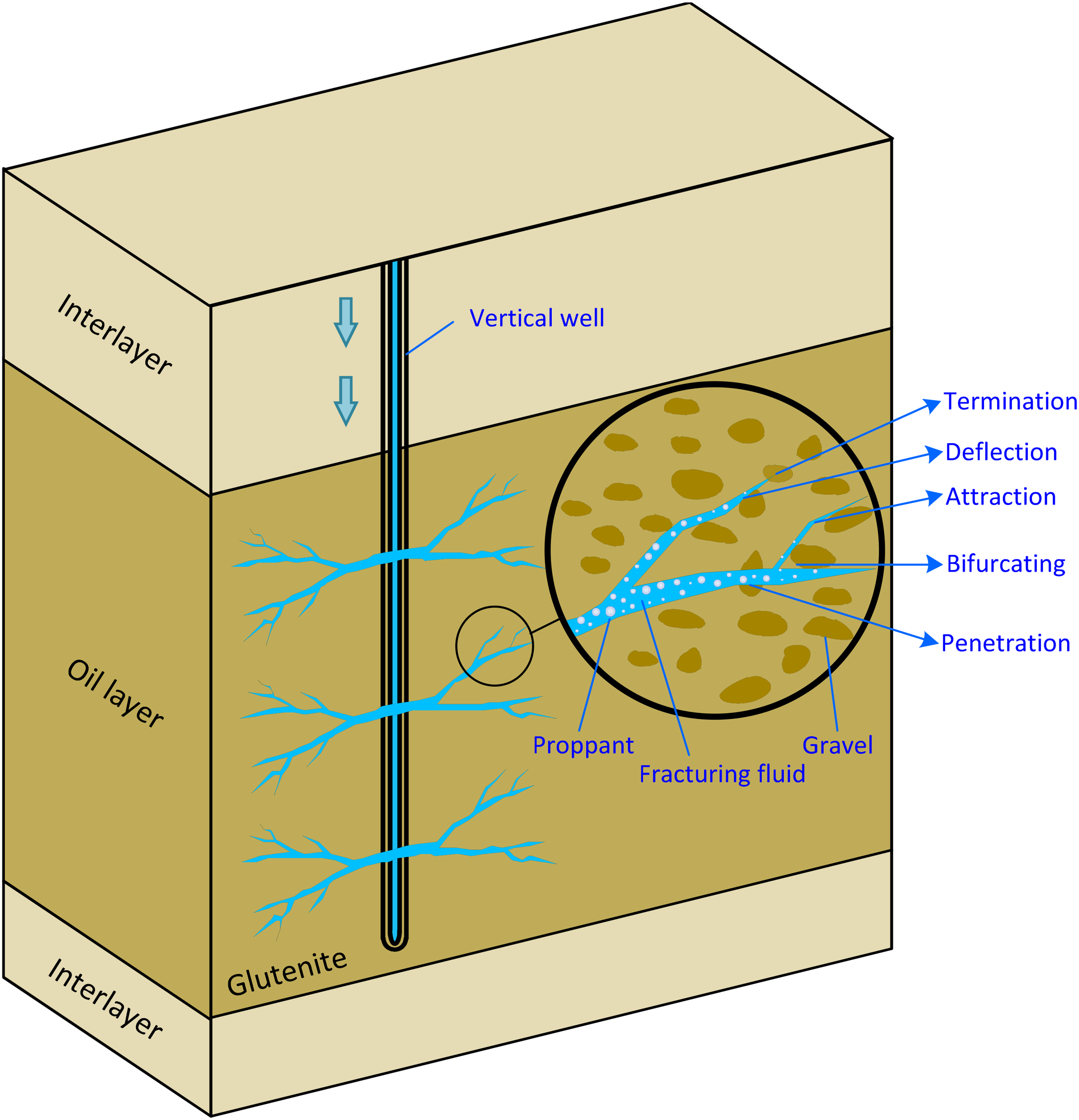
The schematic diagram of complex hydraulic fracture (HF) propagation behavior in glutenite.
Numerical simulation
Governing equations of RFPA3D
To investigate the complex HF propagation behavior and provide direct guidance for pump scheme design and field operation in tight heterogeneous glutenites, a series of numerical simulations were performed based on RFPA3D code (Li et al., 2019; Tang et al., 1998). The reservoir heterogeneity, in addition to the stress–seepage–damage coupling, is considered to simulate the evolution process and complex propagation behavior of HF. An eight-node element was employed as the fundamental element. The mechanical parameters of elements (such as Young's modulus and strength properties) are assumed to follow a Weibull distribution:
Statistical methods, such as Weibull distribution, have been widely used to study the heterogeneity of brittle rocks. For example, Zhu et al. (2004) numerically investigated the fracture behavior of concrete, which is composed of a matrix, aggregate, and bond between them. For field-scale hydraulic fracturing simulation, the input parameters are the mechanical properties of glutenite rock mass. We assume that the mechanical properties of glutenite rock mass conform to the Weibull distribution. To verify the suitability of Weibull distribution and the accuracy of the model, the numerical simulation results will be compared with the field MS monitoring results.
The stress and fluid-flow fields are obtained using the finite-element method (FEM) and the coupling between stress and fluid-flow is governed by Biot's constitutive theory. The basic governing equations in RFPA3D are as follows:


As the damage evolves, Young's modulus of the element gradually decreases, as defined below:
When the tensile stress in the element reaches its tensile strength, 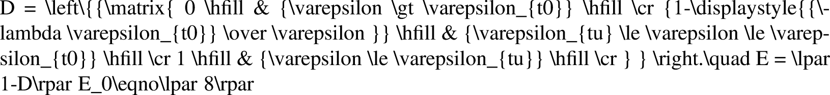
When the equivalent principal tensile strain 
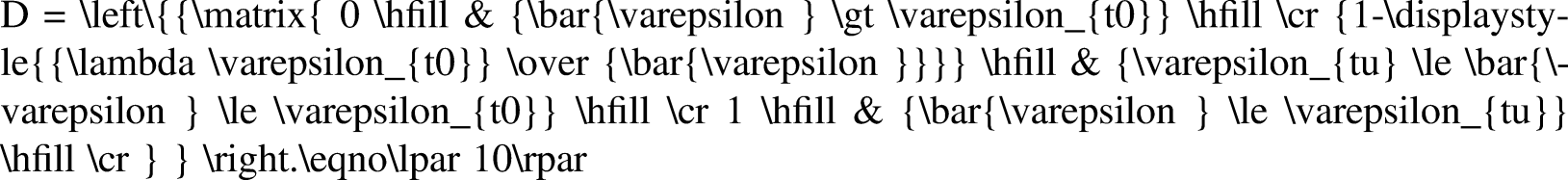


When the Mohr–Coulomb criterion is satisfied for the strength of the element subjected to multiaxial stress, the greatest compressive principal strain 

Numerical simulation model
To improve the stimulated zone and maximize the productivity of tight heterogeneous glutenites, fracturing operations, such as operating procedures and associated treatment parameters, must be optimized to improve HF complexity and SRV. Numerical modeling techniques can overcome the limitations of the physical model in simulation scales and costs, and provide valuable insight into the hydraulic fracturing process. Moreover, it can easily achieve repeated verification of the procedures and parameters involved in the fracturing process and provide an optimal design for fracturing operations. Tan et al. (2017) indicated that physical experiment results can be beneficial for understanding the mechanism of HF propagation, but cannot be used directly in field operation. Hence, field-scale numerical simulations are required to perform optimization analysis. For field-scale hydraulic fracturing simulation, the input parameters are the mechanical properties of glutenite rock mass, instead of the mechanical parameters of matrix or gravels. In this case, the difference in mechanical properties between the matrix and gravel may be weakened. Therefore, we assume that the mechanical properties of glutenite rock mass conform to the Weibull distribution to numerically simulate the glutenite formation. The mechanical parameters of glutenite rock mass are used in the numerical model.
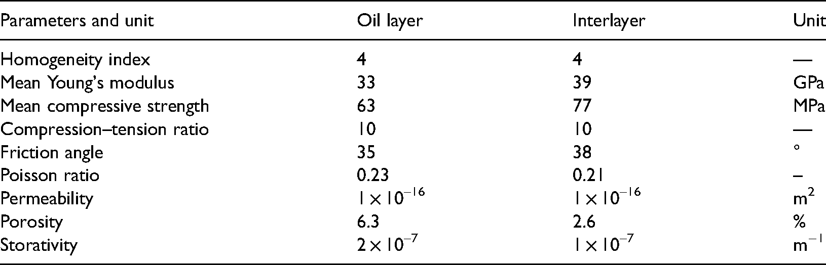
To investigate the complex HF propagation behavior in tight heterogeneous glutenites, a hydraulic fracturing simulation model based on RFPA3D code is established as shown in Figure 11. The X, Y, and Z dimensions of the model are 420, 240, and 120 m, respectively, and are divided into 448,000 FEM units. The thickness of the tight heterogeneous glutenites reservoir is 21 m. To reduce the influence of the boundary effect on fracture propagation, the interlayers with a thickness of 48 and 52 m are set up above and below the reservoir, respectively. The vertical stress, maximum horizontal stress, and minimum horizontal stress of the reservoir are 72, 64, and 57 MPa, respectively. The perforation section with a height of 6 m is prefabricated in the center of the model, which is used to inject fracturing fluid. The viscosity of fracturing fluid is 3 mPa·s, the injection rate is 8.0 m3/min, and the injection time is 64 min. The mechanical parameters of different layers are shown in Table 2. The parameters of oil layers and interlayers are obtained from experimental tests of 42 core samples drilled from a well in Shengli Oilfield.
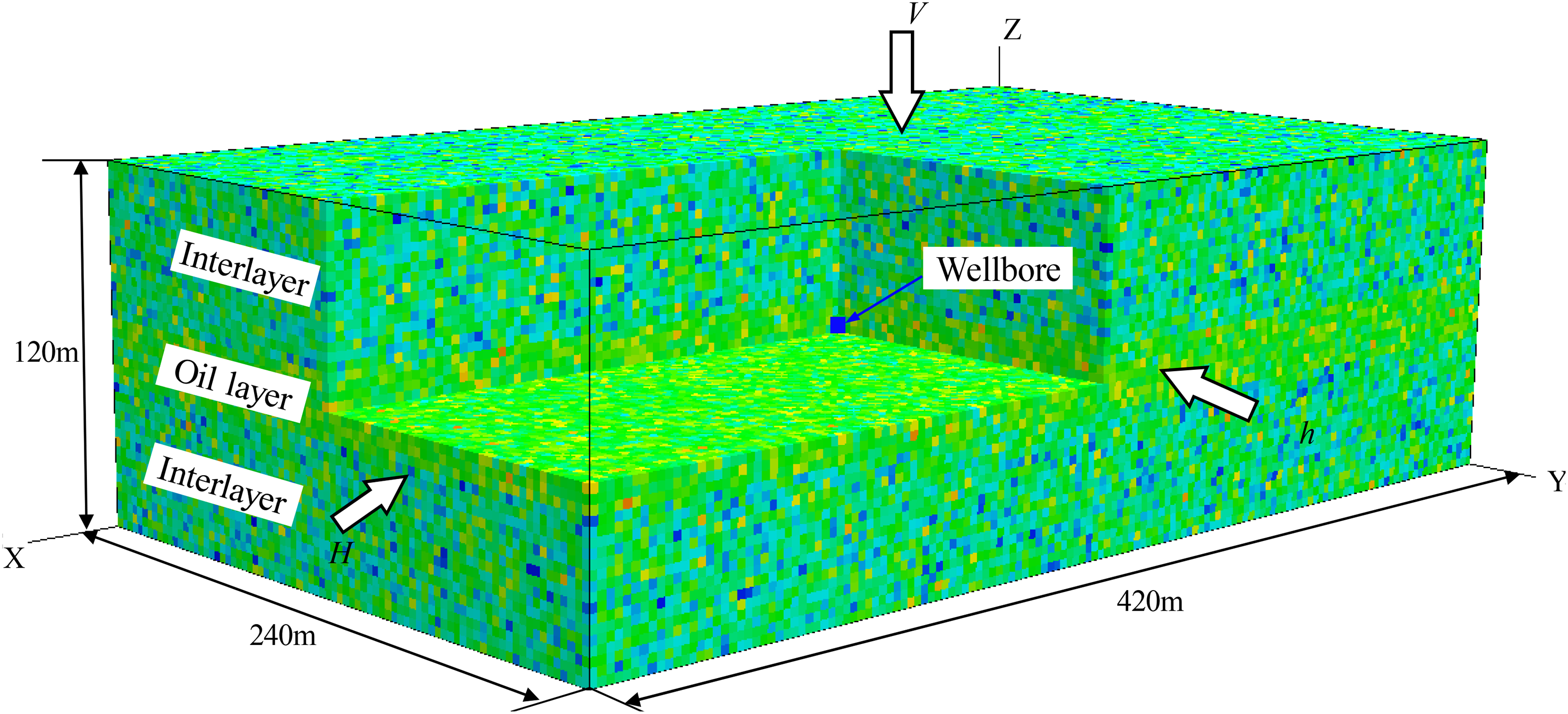
Elastic modulus map of the numerical model for hydraulic fracturing in tight heterogeneous glutenites.
The mechanical parameters of different layers in the numerical model.
Model validation
The fracture geometry and aperture of elements at different fracturing times are illustrated in Figure 12. It is shown that the HF exhibits an X-shaped complex fracture geometry. The fracture length is 210 m and the height is 42 m. The main fracture begins to bifurcate at a fracturing time of 10 min and the secondary fractures at both ends of the main fracture are characterized by highly asymmetric propagation originally. The secondary fractures continue to propagate over time. At first, the two secondary fractures extend in the same direction at a close range; the stress interference between the fractures is quite severe. Thus they are mutually exclusive due to the stress shadow effects, which makes another propagate far away from its path. As they continue to propagate away from each other, the stress interference between them is weakened, and their extension paths tend to be parallel.
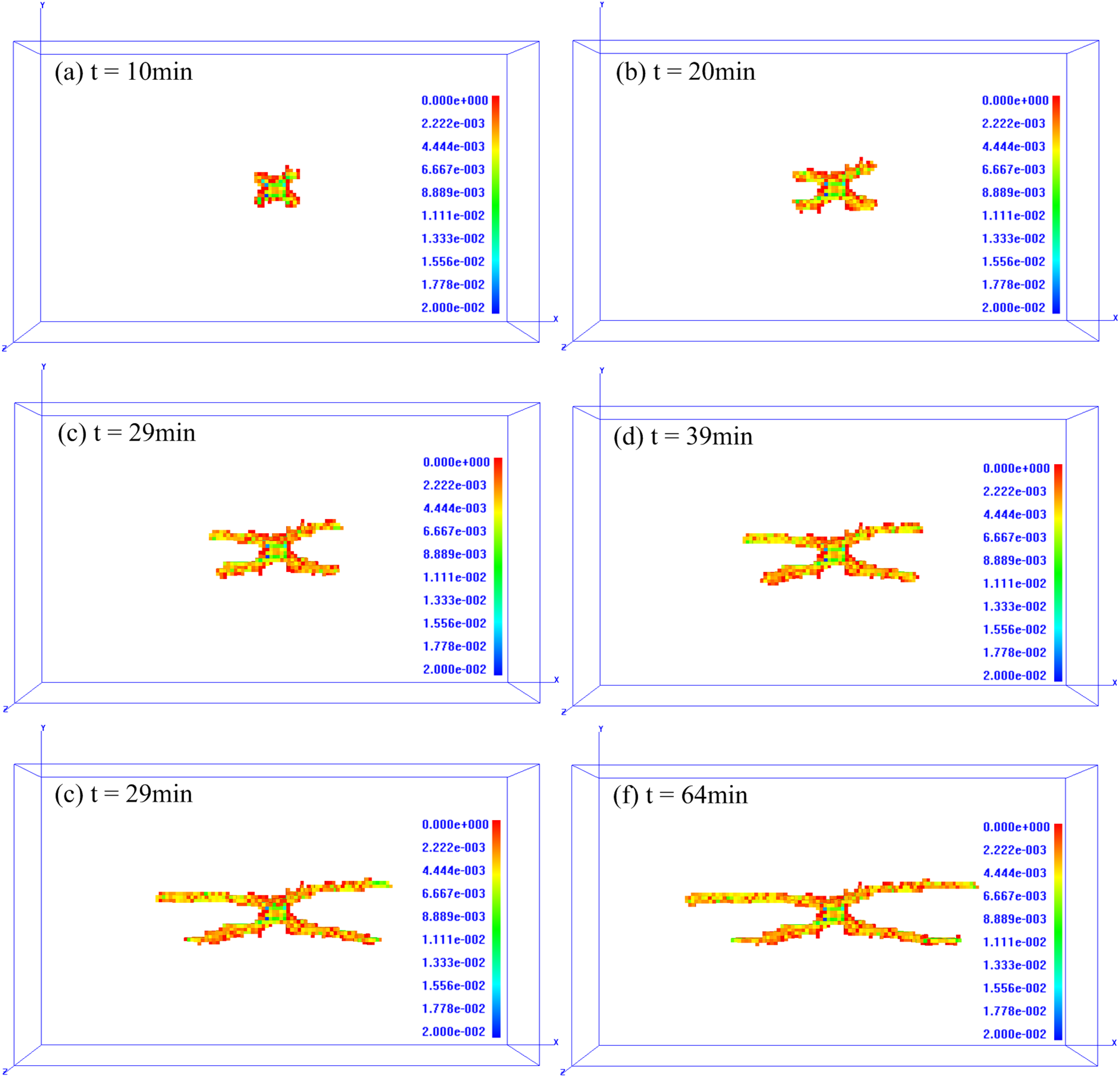
The fracture geometry and aperture of elements at different fracturing times.
According to the historical monitoring data of the target glutenite block in Shengli Oilfield, the drainage radius can be calculated as follows:
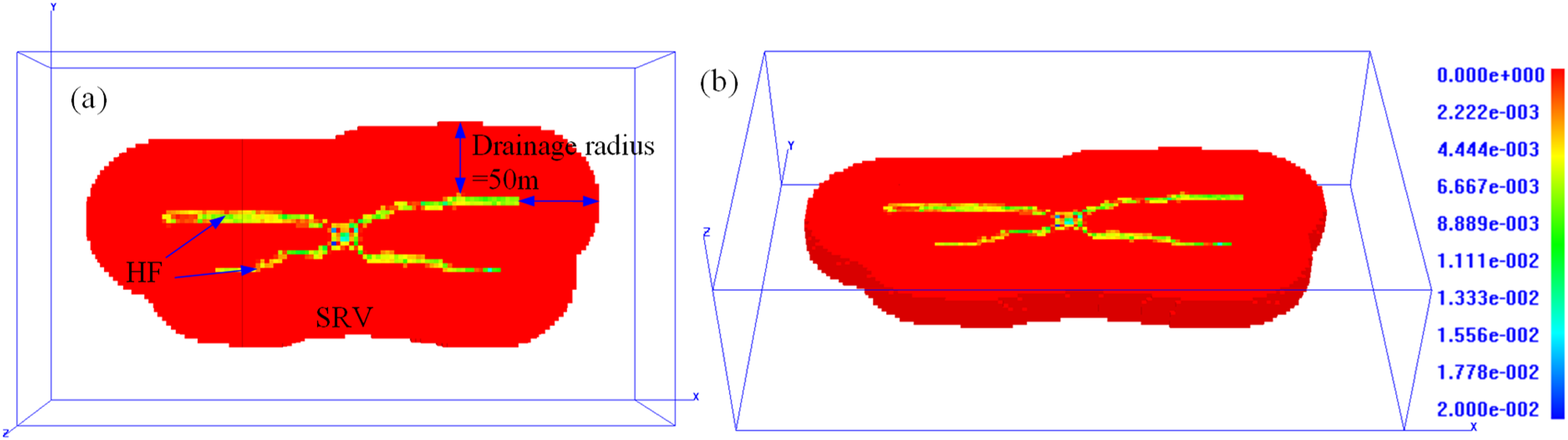
(a) The top view and (b) 3D view of the SRV obtained from RFPA3D.
To verify the accuracy of the numerical model, the MS monitoring data of HFs in well Y222 in Shengli Oilfield were extracted and analyzed. Figure 14 illustrates the HF propagation paths and SRVs obtained from MS monitoring and numerical simulation. Figure 14(a) and (c) presents the top view and 3D view of the MS interpretation results of HF geometry. It is shown that the HF obtained from numerical simulation presents an X-shaped geometry, which is consistent with the results of MS events interpretation. The SRV, length, and height of HF interpreted from MS events are 313,000 m3, 203 m, and 45 m, respectively. Therefore, the SRV and geometric parameters of HFs obtained from MS monitoring and numerical simulation are close, which proves the validity of the numerical model.
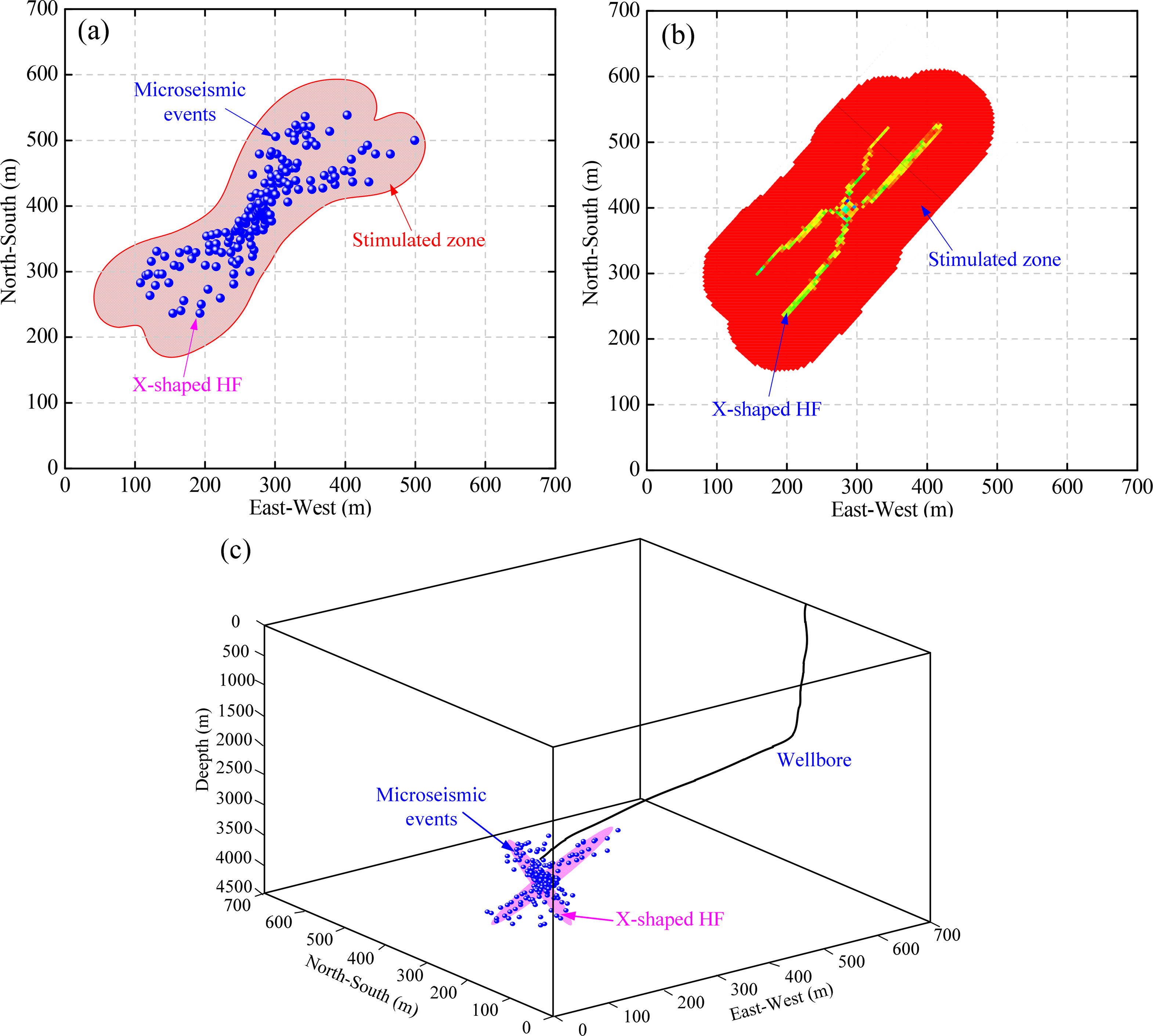
HF propagation paths and SRVs obtained from (a), (c) MS monitoring and (b) numerical simulation.
Simulation results analysis
Effects of variable injection rate fracturing
Simulation scheme design
Currently, the conventional fracturing techniques, e.g. fracturing with a constant injection rate and a single type of fracturing fluid, are widely employed in the treatment of unconventional reservoirs. The fracturing performance often appears to be not working well due to the simple fracture geometry and limited SRV. Therefore, it is worth trying to optimize the fracture geometry and SRV with more effective fracturing technologies. As a newly developed fracturing technology, variable injection rate fracturing has received extensive attention in recent years and has been applied to shale gas development (Cheng et al., 2015; Ciezobka et al., 2016). However, the application effect and fracturing mechanism of variable injection rate fracturing in tight glutenites are rarely studied. The focus of this work is on the investigation of fracture geometry control mechanisms in tight heterogeneous glutenites. To investigate the effects of variable injection rate fracturing on fracturing performance, a series of comparative studies were performed based on the model established above. Four simulation cases with different variable injection rate fracturing modes were designed as follows:
Case 1. Injection rate remains constant: 8.5 m3/min–8.5 m3/min–8.5 m3/min–8.5 m3/min. Case 2. Injection rate monotonically increases: 4 m3/min–8 m3/min–10 m3/min–12 m3/min. Case 3. Injection rate monotonically decreases: 12 m3/min–10 m3/min–8 m3/min–4 m3/min. Case 4. Cyclic variation of injection rate: 4m3/min–13 m3/min–4 m3/min–13 m3/min.
Note that the total fluid volume and the fluid volume of each fracturing stage have a significant influence on the simulation results. Hence, the total fluid volume in each case was set to 680 m3 to eliminate the influence of the fracturing scale on SRV. The fluid volume of each fracturing stage was set to 170 m3 for simplicity. The effects of variable injection rate mode with different fluid viscosities on hydraulic fracturing performance were investigated.
HF geometry and SRV analysis
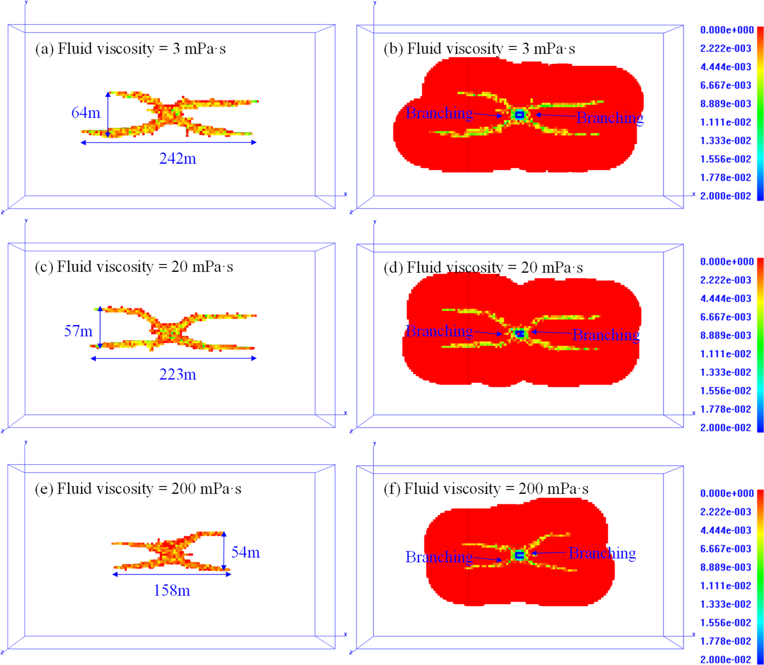
The HF geometry and SRV of each simulation case are illustrated in Figures 15 to 18. The HFs of cases 1, 2, and 3 are all X-shaped fractures, while the HFs of case 4 are more complex. For case 1, the branching behaviors of HFs occur near the wellbore, and the stress shadow effect between branching fractures is severe. As a result, the branching fractures propagate away from each other. As the fracture continues to expand, the stress shadow effect weakens and the branching fractures propagate along the maximum principal stress. With the increase of fluid viscosity, HF length decreases, while HF width decreases first and then increases. The HF width decreases from 54 to 45 m with the fluid viscosity increasing from 3 to 20 mPa·s. The increase of fluid viscosity reduces its filtration effect, which makes it difficult for fracturing fluid to infiltrate into the formation and reduces the possibility of a shear slip or filtration expansion deformation of the rock mass. The HF width increases from 45 to 52 m with the fluid viscosity increasing from 20 to 200 mPa·s, which can be explained that with the increase of fluid viscosity, the fracturing energy increases, as well as the deflection angle of branching fractures (Fallahzadeh et al., 2015). The increase of HF width by fracturing energy exceeds the contribution of fluid filtration effect to the increase of HF width.
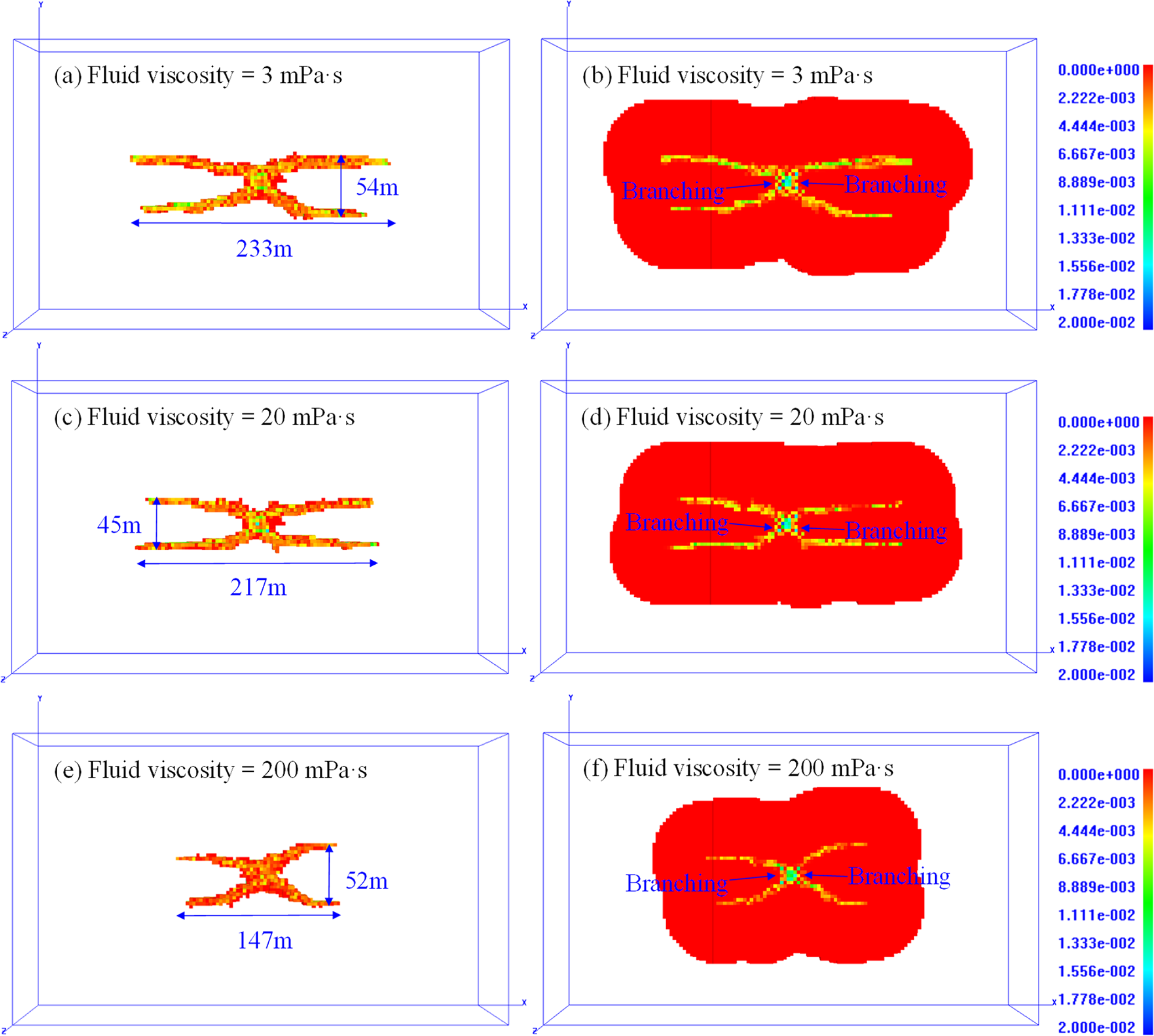
The HF aperture and SRV of case 1.
The HF aperture and SRV of case 4.
The HF geometry and corresponding SRV of case 2 with different fluid viscosities are presented in Figure 16. The HF width, HF length, and SRV decrease with the increase of fluid viscosity. The HF geometries of case 2 are similar to those of case 1, presenting X-shaped fractures. Nonetheless, the HF propagation paths of cases 1 and 2 are quite different. For the HFs of case 2, the injection pressure increases with the increase of the injection rate, resulting in the branching fractures tending to deflect to the direction of minimum principal stress. As a result, the branching fractures no longer propagate in parallel along the direction of the maximum principal stress but continue to propagate along the original path. When a low-viscosity fluid (e.g. 3 mPa·s) is employed, the secondary fractures tend to bifurcate. However, the simulation result is not as expected, as shown in Figure 16. It may be because an insufficient increase in injection rate leads to a limited increase of injection pressure, which is not enough to cause further bifurcation or deflection of the branching fractures.
The HF aperture and SRV of case 2.
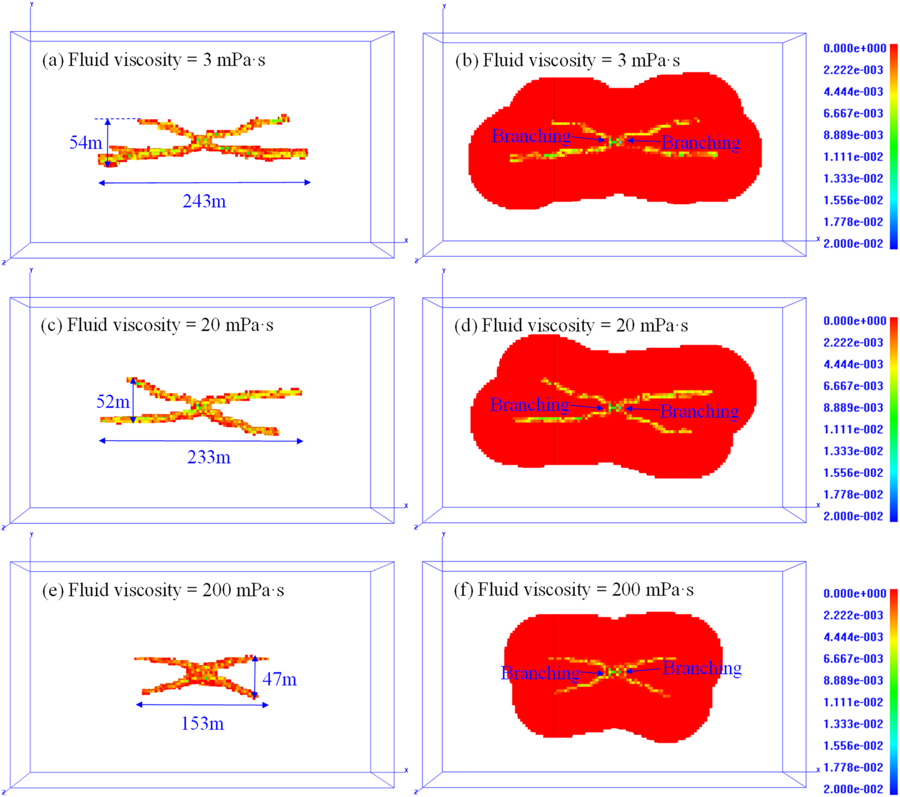
The HF geometry and its corresponding SRV of case 3 with different fluid viscosity are presented in Figure 17. The HF geometries of case 3 are similar to those of cases 1 and 2, presenting X-shaped fractures. The HF width, HF length, and SRV decrease with the increase of fluid viscosity. With a certain fluid viscosity, there is no significant difference in HF length between cases 2 and 3, while the HF width of case 3 is obviously larger than that of case 2. This can be explained that at the early stage of fracturing, a larger injection rate may induce a larger net pressure in the fracture tip, and the main HF tends to overcome the in-situ stress difference and the tensile strength of the rock mass to deflect or bifurcate, and resulting in a larger turning radius of the secondary fracture. The net pressure in the fracture tip decreases with the decrease of the injection rate, and the secondary fractures tend to propagate in parallel along the maximum principal stress due to the reduction or elimination of the stress shadow effect, which is similar to case 1.
The HF aperture and SRV of case 3.
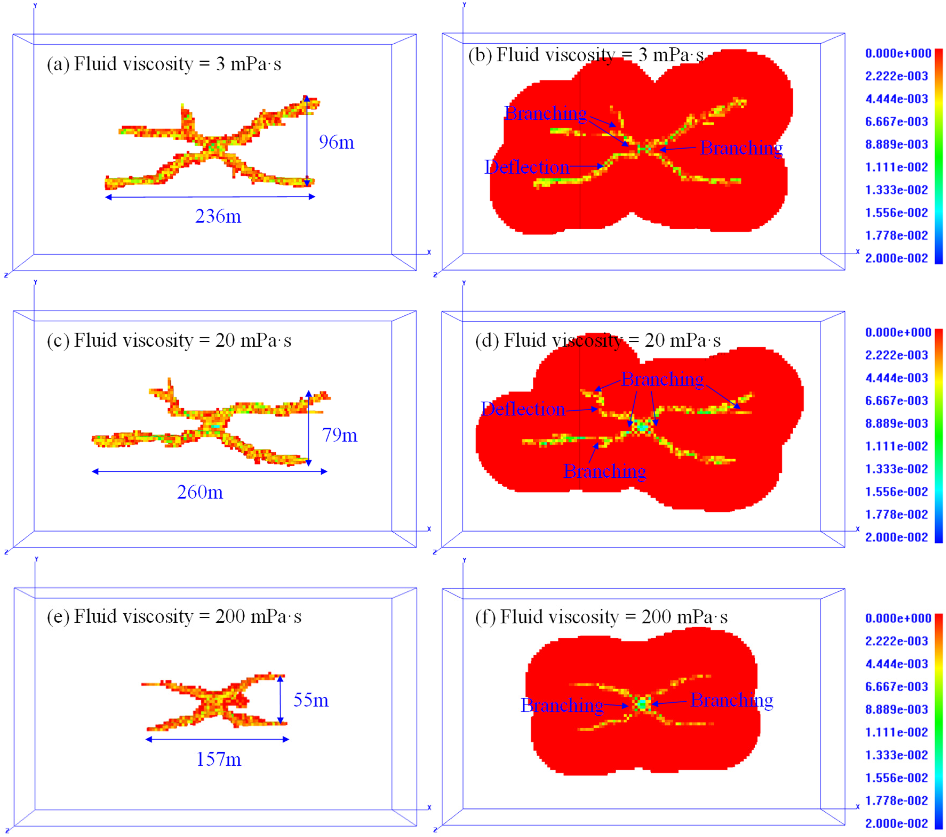
The HF geometry and its corresponding SRV of case 4 (cyclic injection) with different fluid viscosities are presented in Figure 18. The HF geometries with fluid viscosities of 3 and 20 mPa·s are quite different from those with a fluid viscosity of 200 mPa·s. HFs with low and medium fluid viscosity present more complex geometries, and more branching and deflection behaviors occur, as shown in Figures 8(a) to (c). Under high injection pressure and leak-off effect of fracturing fluid, the HF selects the path of least resistance in the glutenite and the random location of the local heterogeneity may result in branching or non-planar propagation of HFs. With the increase of fluid viscosity, the HF width and SRV decrease, while the HF length increases first and then decreases. The turning radii of the branch fractures in case 4 are larger than those of other cases due to the sufficient increase in net pressure resulted from the significant increase in injection rate. When the net pressure in the HF is greater than the horizontal principal stress difference, and the fluid viscosity is low, branch fractures are prone to occur. By creating branch fractures in the area away from the wellbore, the width of the fractured zone can be effectively increased, resulting in an increased SRV.
Effects of variable injection rate mode on SRV
To analyze the effects of variable injection rate mode on SRV, the injection pressure and AE response of each simulation case with fluid viscosity of 3 mPa·s are extracted from RFPA3D, as illustrated in Figure 19. The net pressure in the HF has a significant influence on the difficulty and range of tensile/shear instability of rock mass. The net pressure is determined by the injection pressure and the fracture closure pressure as follows:
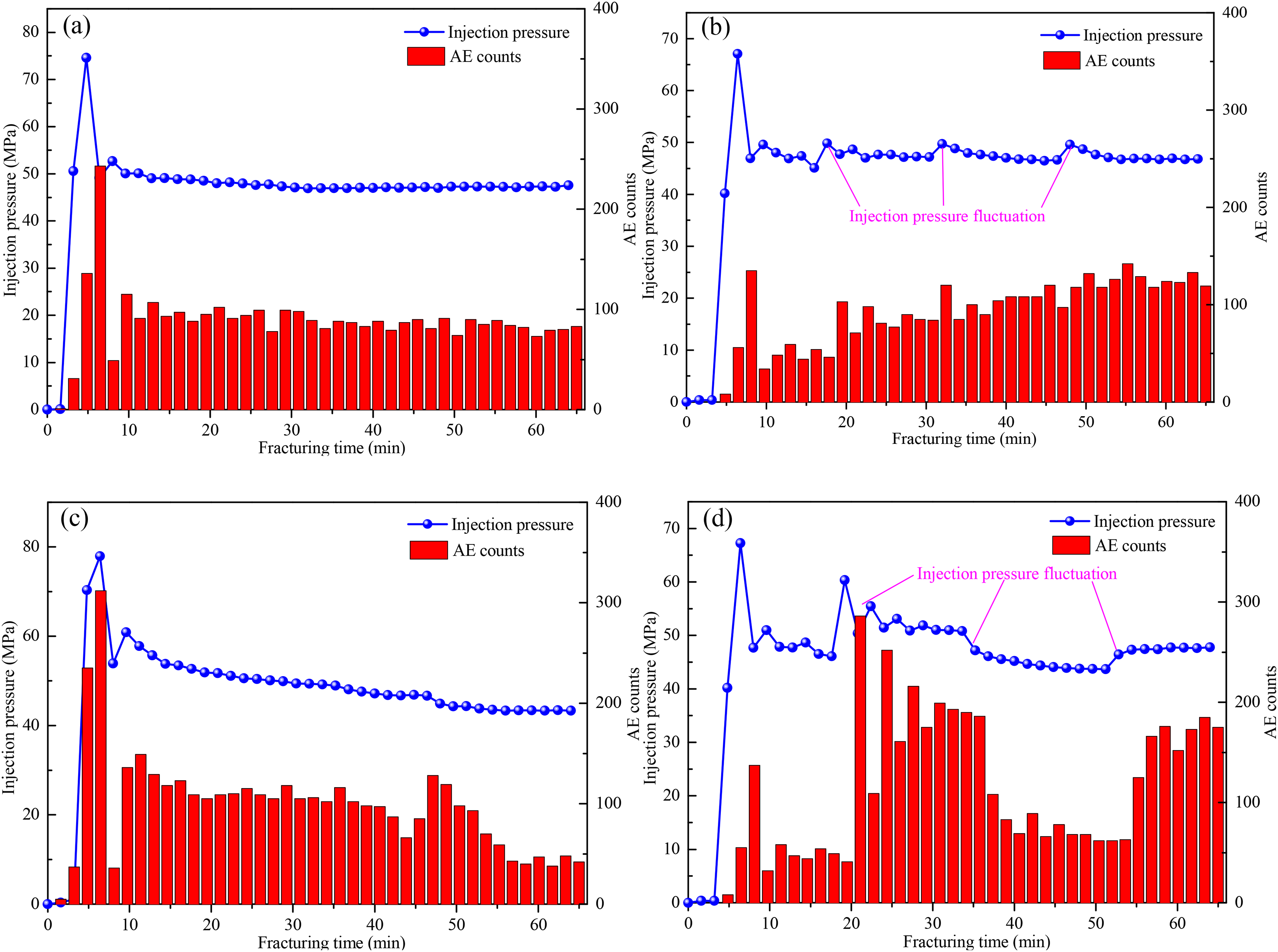
The injection pressure and acoustic emission (AE) response of each simulation case with fluid viscosity of 3 mPa·s.
The injection pressure curves and AE responses of the four cases exhibit different variation characteristics. The injection pressure of case 1 increases rapidly to the breakdown pressure (74.6 MPa) and decreases rapidly to the fracture propagation pressure (48.2 MPa), then remains unchanged. The variation trend of AE counts is basically consistent with that of injection pressure. For case 2, the stepped increase of the injection rate leading to the fluctuation of injection pressure and the AE counts increase slowly after fracture initiation. However, the increase in injection pressure is limited (<6 MPa) and is not enough to deflect or bifurcate the secondary HFs. For case 3, the injection rate decreases monotonously from 12 to 4 m3/min, leading to a maximum breakdown pressure (77.9 MPa) and a decrease in injection pressure and AE counts after fracture initiation. This fracturing mode may create complex fractures at the near-wellbore zone, but it is difficult to bifurcate or divert the secondary fractures. For case 4, the cyclic variation of injection rate between 4 and 13 m3/min causes evident fluctuations in injection pressure and AE counts. Cyclic injection of a low-viscosity fluid is beneficial to achieve high net pressure and large-scale fluid leak-off in the formation, which may promote the increase of the width of the fractured zone. Variable injection rate fracturing generates pressure fluctuation in the HFs, resulting in the discontinuous deformation of the rock matrix, thereby inducing the fractures to tensile or shear failure. A great fluctuation of injection pressure and a high induced net pressure may facilitate the bifurcation and diversion of secondary HFs and improve the HF complexity. In the process of hydraulic stimulation of tight heterogeneous glutenites, the key to improving fracture complexity is to increase the net pressure in HFs, cause evident pressure fluctuations, and activate or communicate a wide range of natural discontinuities.
Figure 20 illustrates the effects of variable injection rate mode on SRV under different fluid viscosity. The fracturing performance of variable injection rate technology is better than that of conventional constant injection rate technology. Case 4 has the largest SRV, thus the fracturing performance is the best among the four cases. As discussed above, when the injection of case 4 increases from 4 to 13 m3/min, the net pressure in the fracture increases significantly, which induces the main fracture to bifurcate and deflect, thus improving the HF complexity and SRV. Case 3 has the second-largest SRV, indicating that it is also feasible to improve SRV by creating complex fractures around the wellbore. Compared with case 1, the increase of SRV in case 2 is not obvious, which may be caused by insufficient injection pressure increment to make fracture bifurcate or deflect. Therefore, when employing variable injection rate technology in tight heterogeneous glutenites, cyclic variable injection rate mode with a low-viscosity fluid is recommended to facilitate fracture bifurcation and deflection.
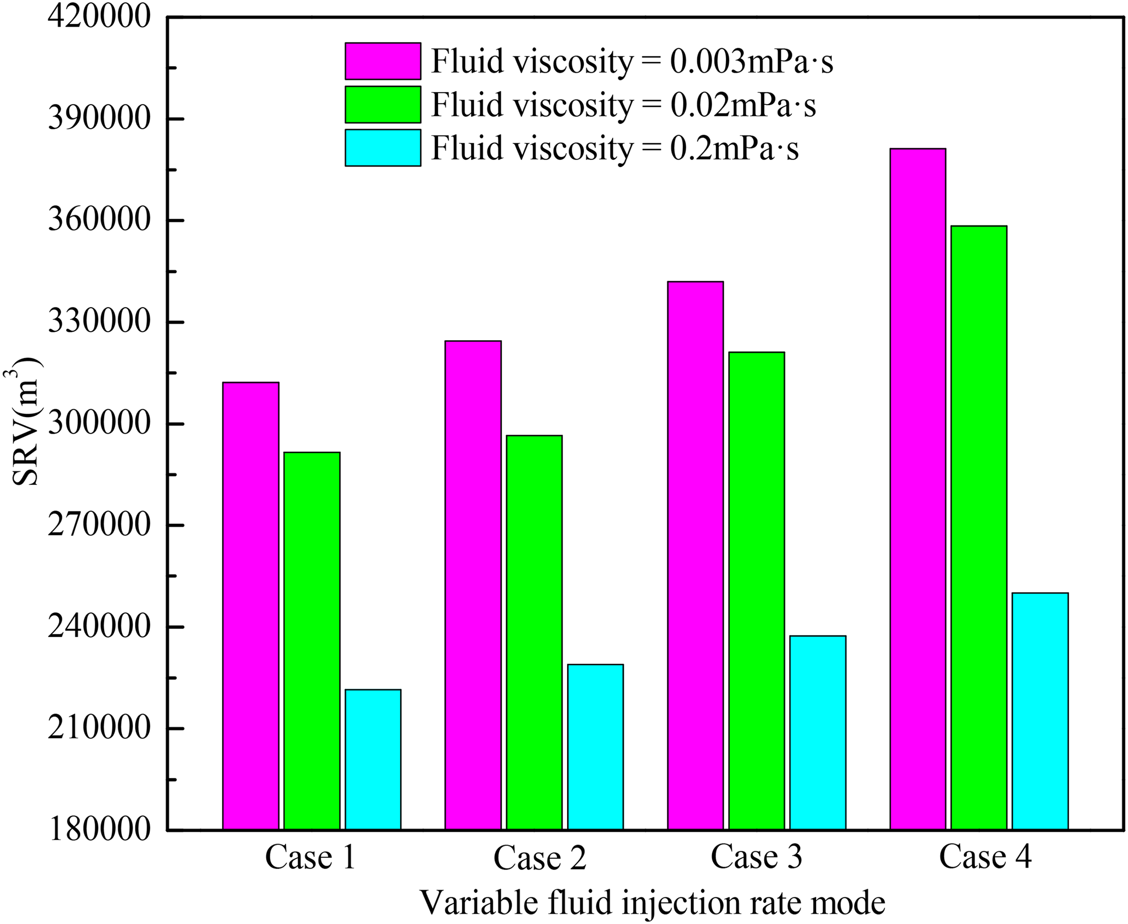
Effects of variable injection rate mode on stimulated reservoir volume (SRV) under different fluid viscosity.
Effects of simultaneous variable injection rate and fluid viscosity fracturing
Operating procedure design
It can be concluded from above that it is difficult to create more complex HFs or fracture networks through variable injection rate fracturing in tight heterogeneous glutenites. To create more secondary and tertiary fractures, activate natural cracks, and maximize SRV, operating procedures should be reasonably designed and optimized. High injection rate and low fluid viscosity tend to facilitate HFs connection with more weak planes and strengthen the generation of complex HFs. The increasing injection rate can increase the net pressure in the fracture tip and promote the bifurcation and diversion of HFs. According to the formation mechanisms of complex HFs obtained from the laboratory experiment, the tensile events tend to appear during the initiation stage of HF growth, most are located around the wellbore, while shear events and compressive events appear primarily around the branch fractures and non-planar extension fractures, most are located in the area away from the fracturing well. The shear and compressive mechanisms generally dominate with an increase in the HF complexity. High-viscosity fracturing fluid is beneficial for the generation of tensile fractures near the wellbore, while the low-viscosity fracturing fluid is more likely to create shear fractures in the area away from the wellbore.
Low-viscosity fracturing can promote artificial fractures to connect with natural discontinuities and increase the complexity of HFs but will cause difficulty in sand adding and short propped fractures. However, field operations in glutenites of Shengli Oilfield indicated that simply increasing the injection rate or lowering the fluid viscosity may not be enough to significantly improve the HF complexity (Zhang et al., 2019). Therefore, a simultaneous variable injection rate and fluid viscosity fracturing technology is first proposed, which involves an appropriate arrangement of operating procedures and corresponding treatment parameters. Attempts were made in this section to optimizing SRV by coordinating operating procedures, which means employing different combinations of treatment parameters at different fracturing stages.
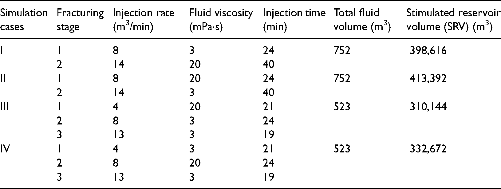
Two injection strategies are proposed through the analysis of fracturing stimulation issues of tight heterogeneous glutenites in Shengli Oilfield. Four simulation cases, as listed in Table 2, have been designed according to the two injection strategies, which are as follows: (a) complex fractures are first created at the near-wellbore zone to increase the fracture complexity, and then multistage branch fractures are created far away from the wellbore, as shown in Figure 21(a); (b) the main fracture is first created at the near-wellbore zone to ensure the length of final HF, and then complex fractures or fracture networks with multistage branch fractures are created far away from the wellbore, as shown in Figure 21(b). In the field fracturing operation, the injected fracturing fluid will compress the rock mass on both sides of the HFs, causing damage to the surrounding rock mass and inducing microcracks, as shown in Figure 21. The treatment process is divided into two or three stages for each simulation case. The simulation cases I and II are designed according to injection strategy a, while the simulation cases III and IV are designed according to injection strategy b. The total fluid volume and resulting SRV of each simulation case are also listed in Table 3.
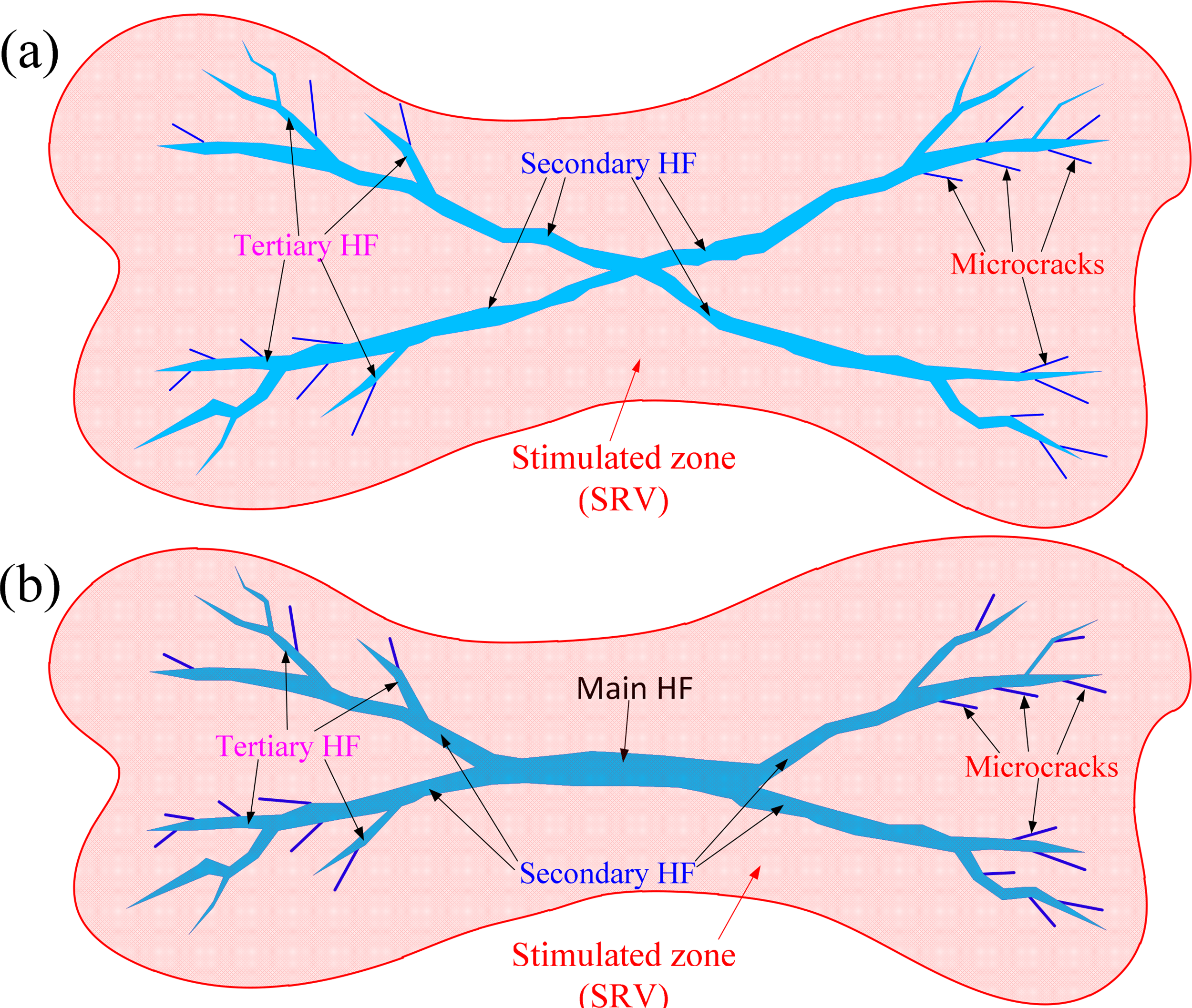
Schematic diagrams of hydraulic fracture (HF) geometries of (a) injection strategy a and (b) injection strategy b.
Numerical simulation schemes of simultaneous variable injection rate and fluid viscosity fracturing.
HF geometry and SRV analysis
Figures 22 to 25 show the HF and SRV evolution process for the four simulation cases of simultaneous variable injection rate and fluid viscosity fracturing. Comparing the HFs created with different fracturing technologies, the HF geometries of simultaneous variable injection rate and fluid viscosity fracturing are more complex than those of conventional constant injection rate fracturing and variable injection rate fracturing. Many secondary and tertiary fractures can be induced by simultaneous variable injection rate and fluid viscosity fracturing, which is conducive to the control of fracture geometry. The fracturing behaviors are mainly branching and deflection in field-scale stimulation.
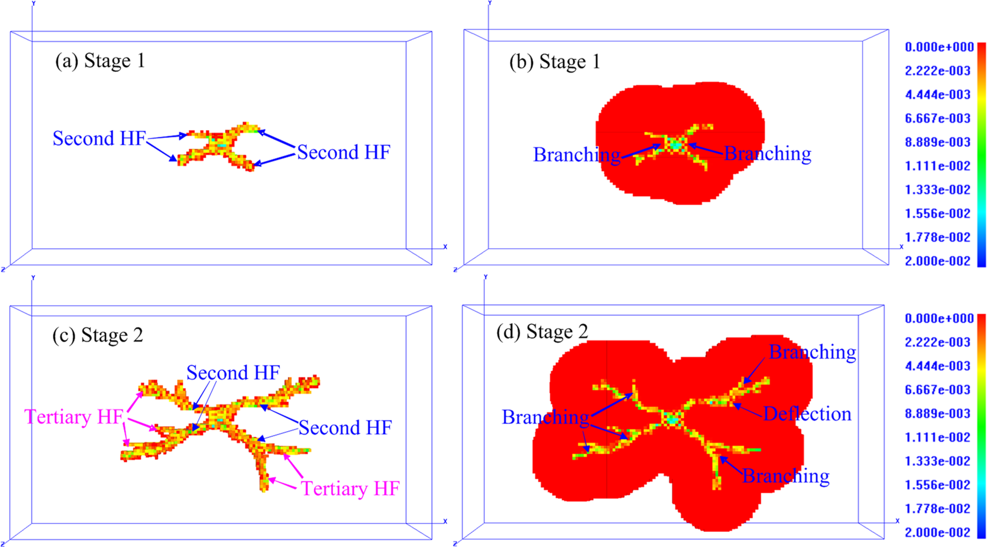
The HF aperture and SRV of case I at different fracturing stages.
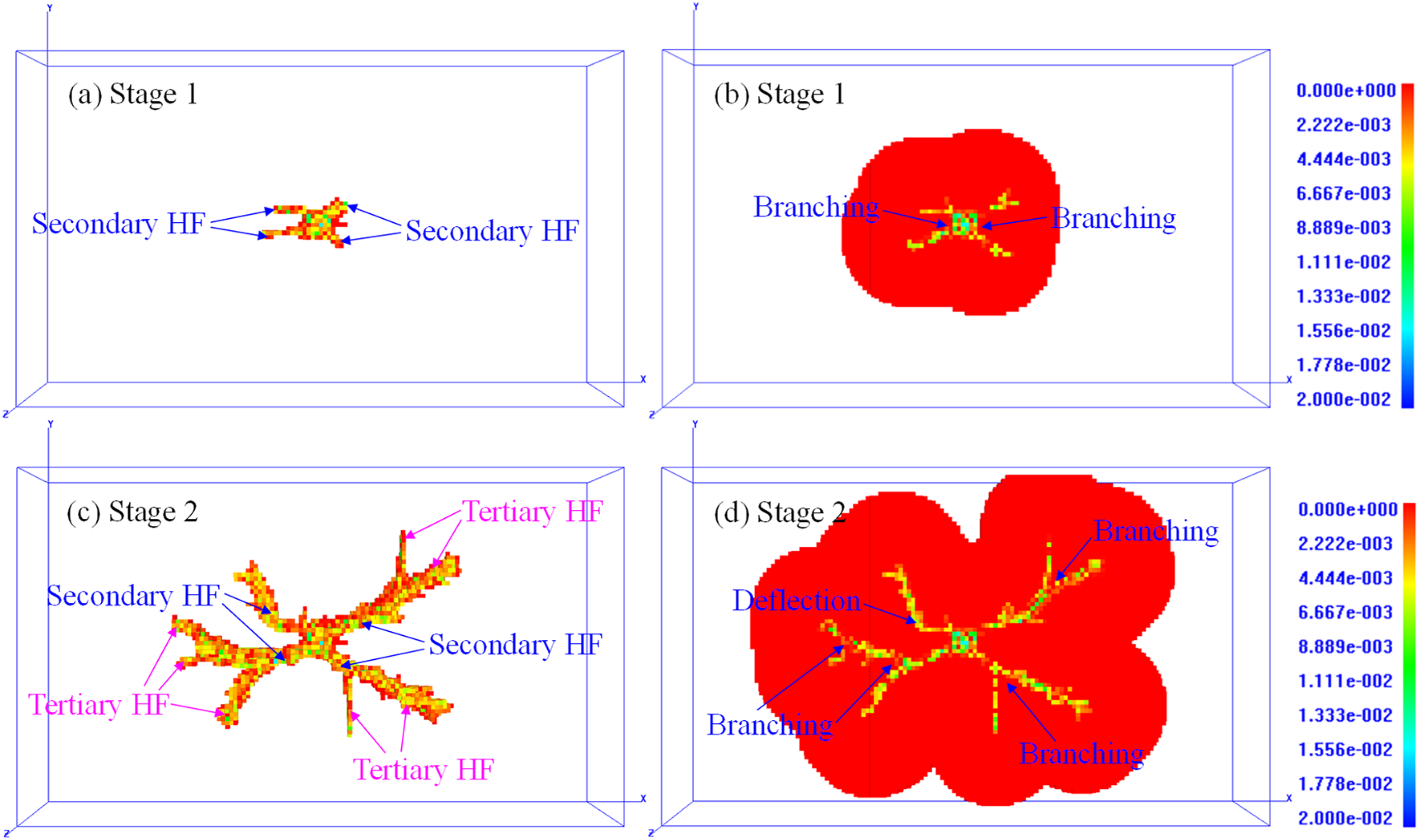
The HF aperture and SRV of case IV at different fracturing stages.
For case I, the medium injection rate and low-viscosity fluid are employed at the first fracturing stage to induce the fractures to tensile failure and create complex fractures near the wellbore, and then the injection rate and fluid viscosity are increased to induce the fractures to shear failure, thus creating secondary fractures far away from the wellbore. The HF presents a very complex geometry, which is mainly composed of secondary fractures and tertiary fractures, as shown in Figure 22. For case II, the medium injection rate and medium-viscosity fluid are employed to create an X-shaped fracture at the first fracturing stage, then the low-viscosity fluid is injected at a high injection rate, resulting in a complex geometry of HF with numerous secondary and tertiary fractures. The HF geometry of case II is more complex than that of case I, as shown in Figure 23. The width of the stimulated zone of case II is larger than that of case I, too.
The HF aperture and SRV of case II at different fracturing stages.
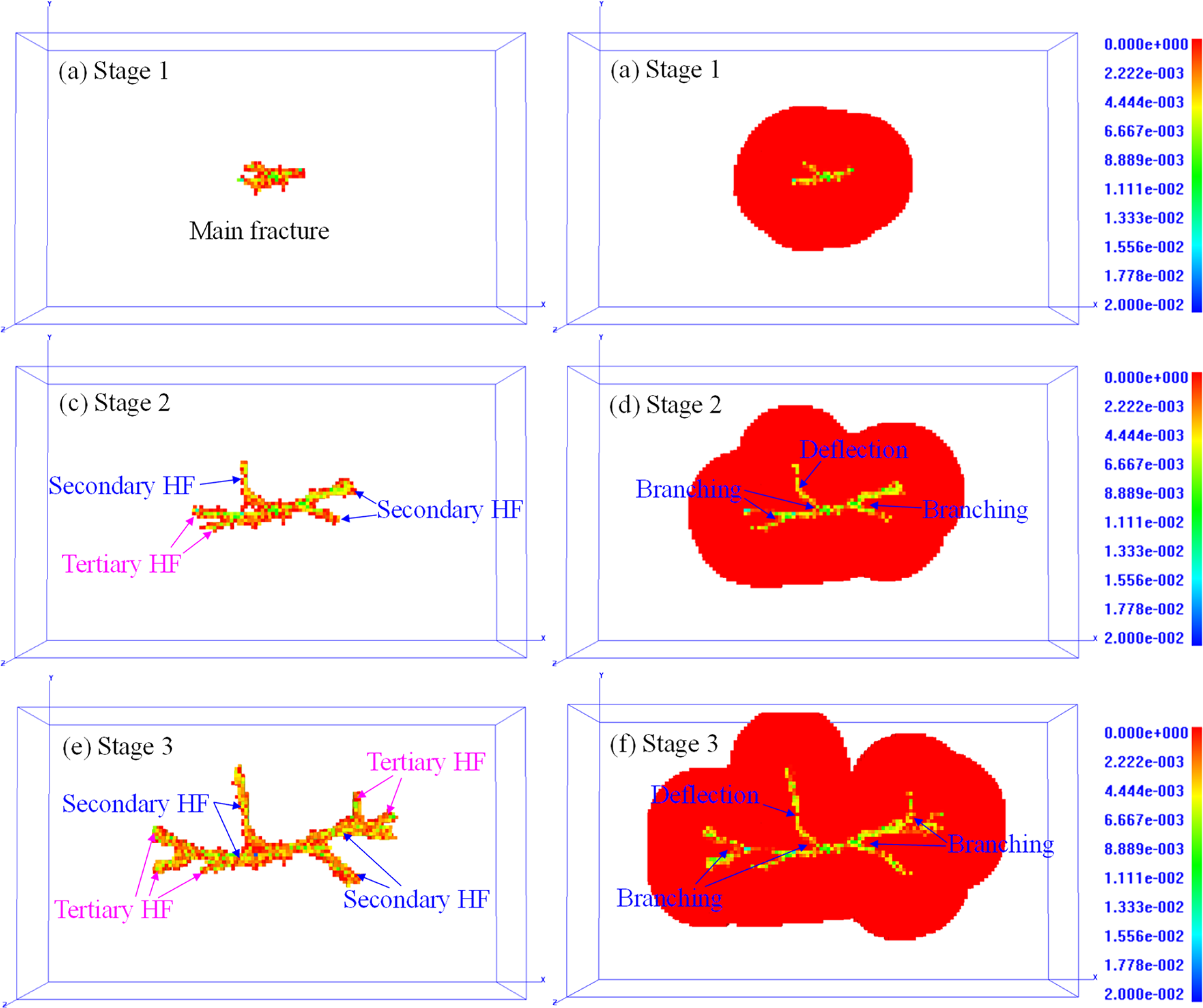
The fracturing operation process of case III is divided into three stages: the small injection rate and medium-viscosity fluid are used at the first fracturing stage to create a simple long fracture near the wellbore, and then the medium injection rate and low-viscosity fluid are used to make the main fracture branch, finally, high injection rate and low-viscosity fluid are used to promote the fracture to bifurcate or deflect again. The HF geometry is shown in Figure 24. Although there are several secondary and tertiary fractures, its SRV is smaller than that of case II, the reason may be the fracturing time with a large injection rate of case III is relatively short, and the increased net pressure in the HF from stage 2 to stage 3 is limited. Therefore, increasing the fracturing time of the operating stage with a large injection rate is conducive to increasing the width of the stimulated zone, which can help improve the HF complexity and SRV.
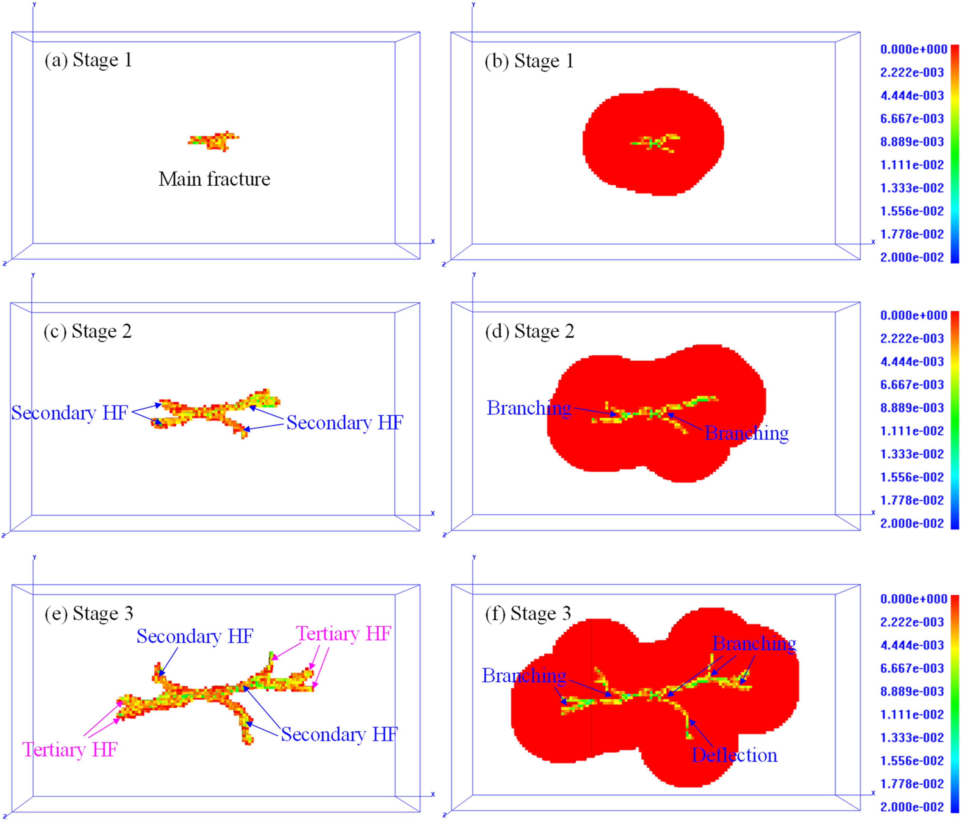
The HF aperture and SRV of case III at different fracturing stages.
The operating procedure of case IV is similar to that of case III, thus the HF geometries of the two cases are quite similar. The HFs present complex geometries, which are mainly composed of main fractures, secondary fractures, and tertiary fractures, as shown in Figures 24 and 25. The difference between cases III and IV is the sequence of alternating fluid injection (variable fluid viscosity) in the first and second stages, as presented in Table 2. In the first fracturing stage, main fractures are created with a low injection rate of 4 m3/min for both cases III and IV. In the second fracturing stage, the injection rates are elevated to 8 m3/min, low-viscosity fluid is used for case III, while medium-viscosity fluid is used for case IV. The increase of both injection rate and fluid viscosity in the second fracturing stage for case IV leads to the evident increase of injection pressure. Therefore, secondary fractures, even tertiary fractures, are likely to be created, as shown in Figure 25(c).
Effects of simultaneous variable injection rate and fluid viscosity mode on SRV
The injection pressure curve, AE response, and fracture geometry of different fracturing stages for the four simulation cases are illustrated in Figure 26. The evolution of SRV of each simulation case is illustrated in Figure 27. The SRV increases with the increase of fracturing time. After the injection rate is increased and the fracturing fluid is switched, the SRVs of cases I and II increase significantly due to the bifurcation or deflection of secondary fractures.
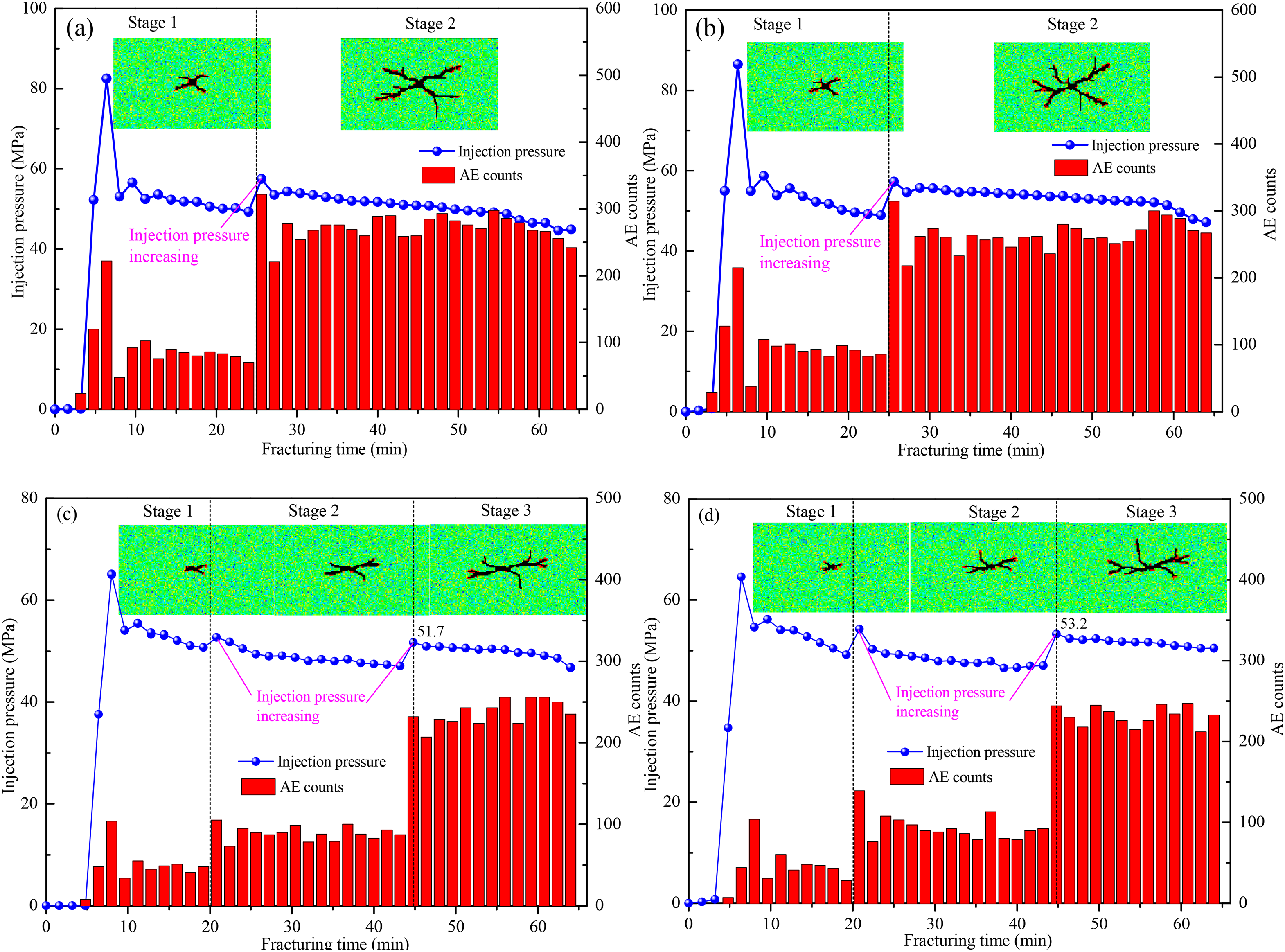
The injection pressure, acoustic emission (AE) response and fracture geometry of different fracturing stages for the four simulation cases: (a) case I, (b) case II, (c) case III, (d) case IV.
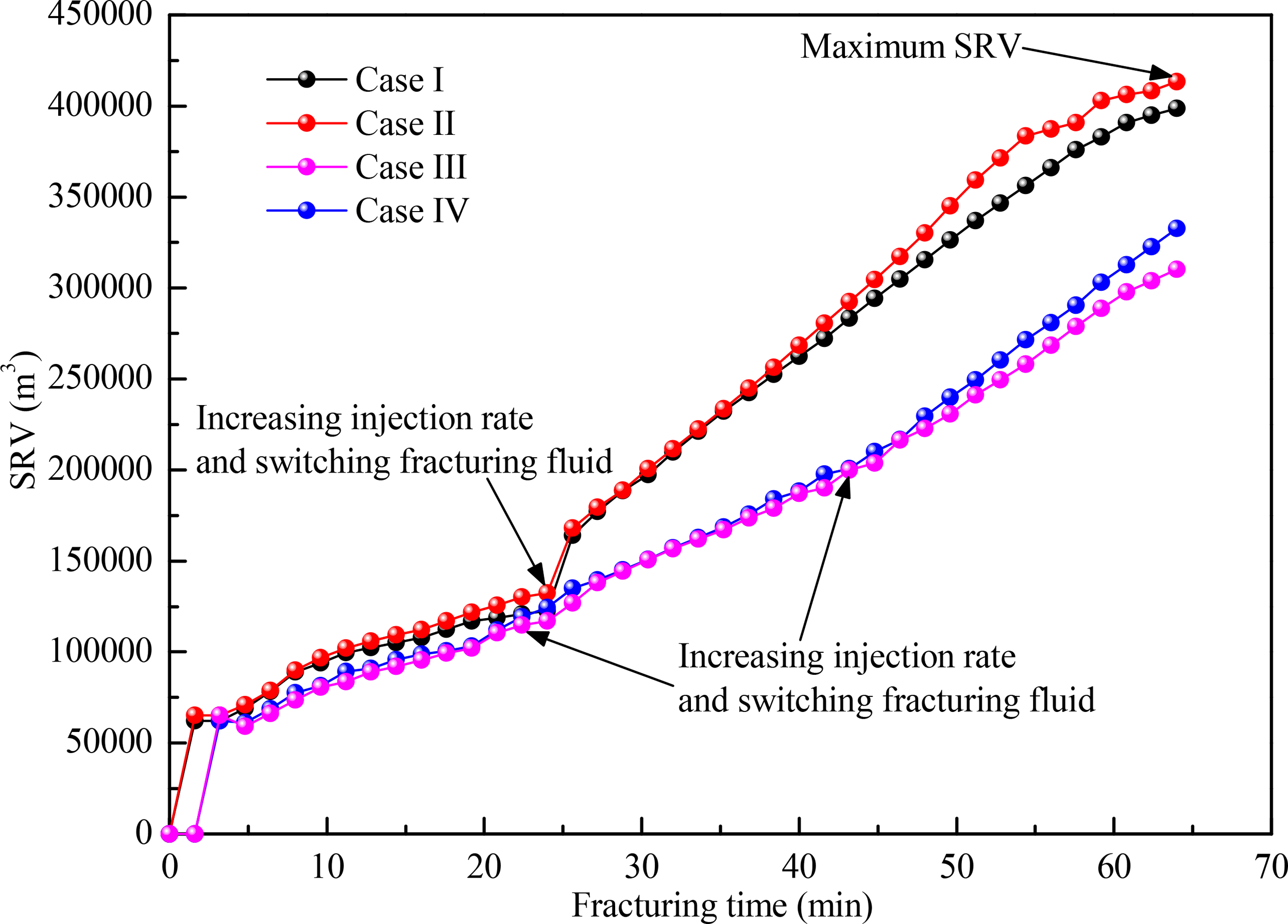
The evolution of stimulated reservoir volumes (SRVs) of different simulation cases.
The injection pressure curves and AE responses of cases I and II exhibit similar variation characteristics. In stage 1, the X-shaped complex HFs are created with a medium injection rate (8 m3/min) for both cases I and II. Then the injection rate is elevated to 14 m3/min at stage 2, and the injection pressure is increased rapidly; the deflection and branching behaviors occur on secondary HFs, and several tertiary HFs are induced. Consequently, AE counts increase significantly from stage 1 to stage 2. In stage 1, low-viscosity fluid is used for case I while medium-viscosity fluid is used for case II. The tertiary fractures appear in case II, but not in case I. This phenomenon shows that increasing the pressure in the fracture is beneficial to the fracture bifurcation. As a result, the SRV of case II is larger than that of case I at the end of stage 1. In stage 2, the injection rate is elevated to 14 m3/min, low-viscosity fluid is used for case II while medium-viscosity fluid is used for case I. The injection pressure increases with the increase of injection rate, thus the HFs have enough energy to deflect or bifurcate. Low-viscosity fluid has better filtration capacity and can strengthen the interaction between the HF and natural discontinuities to form complex fractures. Therefore, the HF of case II is more complex and the SRV of case II is larger than that of case I.
The injection pressure curves and AE responses of cases III and IV exhibit similar variation characteristics. In stage 1, the main HFs are created with a low injection rate (4 m3/min) for both cases III and IV. Then the injection rate is elevated to 8 m3/min, and the injection pressure is increased, as well as the AE counts. In stage 2, low-viscosity fluid is used for case III while medium-viscosity fluid is used for case IV. The injection pressure increases significantly from 49.1 to 54.3 MPa for case IV, due to the simultaneous increase of injection rate and fluid viscosity. In stage 2, the injection pressure of case IV is higher than that of case III. In stage 3, high injection rate and low-viscosity fluid are used for both cases III and IV. Due to the higher net pressure of HF of case IV, as shown in Figure 26(c) and (d), the HF is more likely to deflect or bifurcate. Therefore, the HF of case IV is more complex and the SRV of case IV is larger than that of case III.
Field operations and laboratory observations suggested that a high injection rate and low-viscosity fluid can increase the net pressure in the fracture and communicate with a wide range of natural discontinuities, and facilitate the generation of complex HFs (Guo et al., 2014; Huang et al., 2020; Lyu et al., 2020). High net pressure in the fracture and evident pressure fluctuation induced by the variation of treatment parameters may be beneficial for HF turning and bifurcation. To obtain a favorable complex fracture or fracture network, the operating procedures must be appropriately designed. The simultaneous variable injection rate and fluid viscosity technology can facilitate the generation of multiscale HF systems and effectively improve the HF complexity and SRV. The fracturing mechanism of the simultaneous variable injection rate and fluid viscosity technology is to open and connect natural discontinuities at different fracturing stages, and continuously increase the net pressure in the HF to promote its branching and diversion and improve the fracture length and complexity. The key of this technology is to determine the optimal timing and range to change the fluid volume, fluid viscosity, and injection rate at each fracturing stage. Although it is impossible to enumerate all the procedure combinations, numerical simulations can help us to evaluate and optimize the fracturing design scheme ahead of time. Nonetheless, how to give the best combination of treatment parameters at different fracturing stages and to determine the optimal timing and range to change these parameters for a certain tight heterogeneous glutenite still has a long way to go.
Conclusion
In this paper, a large-scale experimental test on glutenite specimens was conducted and the HF propagation behaviors and the focal mechanism of AE events and MS events were analyzed. A 3D numerical model of hydraulic fracturing was developed to reproduce the complex HF evolution process. The numerical model was validated by the actual HF interpreted from MS monitoring data. The variable injection rate fracturing and simultaneous variable injection rate and fluid viscosity fracturing technology were numerically simulated to investigate the effects of operating procedures on HF geometry and SRV in tight heterogeneous glutenites. The results provided a valuable insight into the initiation and propagation of complex fractures and SRV enhancement strategy in heterogeneous tight heterogeneous glutenites, which was of innovative value for fracturing scheme design and treatment parameters optimization. The conclusions were as follows:
Various HF propagation behaviors, namely, termination, penetration, deflection, and branching, are observed from a laboratory experiment on glutenite specimens. The glutenite is more difficult to form a complex fracture or fracture network than shale and coal due to a less-developed natural fracture system. However, the strong heterogeneity of the matrix and the presence of gravels make it possible to form complex fractures in tight heterogeneous glutenites. From the focal mechanism of glutenite fracture, tensile events tend to appear during the initiation stage of HF growth, most are located around the wellbore. Shear events and compressive events appear primarily around the branch fractures and non-planar extension fractures, most are located in the area away from the fracturing well. The shear and compressive mechanisms generally dominate with an increase in the HF complexity. The key to improving fracture complexity is to increase the net pressure in HFs, cause evident pressure fluctuations, and activate or communicate a wide range of natural discontinuities. A high injection rate and low-viscosity fluid are recommended to improve the HF complexity and SRV. The fracturing performance of variable injection rate technology is better than that of conventional constant injection rate technology. The cyclic variable injection rate mode with a low-viscosity fluid can promote the fracture bifurcation and diversion, and obtain a maximum SRV among the simulation cases of variable injection rate fracturing in this research. A simultaneous variable injection rate and fluid viscosity technology is proposed to facilitate the generation of multiscale HFs and effectively improve the HF complexity and SRV. Moreover, two injection strategies with respect to simultaneous variable injection rate and fluid viscosity technology are proposed to achieve the control of HF geometry. The key of this technology is to determine the optimal timing and range to change the fluid volume, fluid viscosity, and injection rate at each fracturing stage.
Footnotes
Acknowledgements
The authors express their sincere thanks to the reviewers for their helpful comments and suggestions for improving this paper.
Declaration of conflicting interests
The authors declared no potential conflicts of interest with respect to the research, authorship, and/or publication of this article.
Funding
The authors disclosed receipt of the following financial support for the research, authorship, and/or publication of this article: This work was conducted with support from the National Natural Science Foundation of China (Grant Nos. 51879041 and 51761135102) and the Fundamental Research Funds for the Central Universities (No. N180105029).